
Related Manuals for Campbell RF401A Series


Summary of Contents for Campbell RF401A Series
- Page 1 RF401A-Series Spread Spectrum Radios Revision: 2/18 C o p y r i g h t © 2 0 0 1 - 2 0 1 8 C a m p b e l l S c i e n t i f i c , I n c .
- Page 3 Quotations for repairs can be given on request. It is the policy of Campbell Scientific to protect the health of its employees and provide a safe working environment, in support of this policy a “Declaration of Hazardous Material and Decontamination”...
- Page 5 PLEASE READ FIRST About this manual Please note that this manual was originally produced by Campbell Scientific Inc. primarily for the North American market. Some spellings, weights and measures may reflect this origin. Some useful conversion factors: Area: 1 in...
- Page 7 • Periodically (at least yearly) check electrical ground connections. WHILE EVERY ATTEMPT IS MADE TO EMBODY THE HIGHEST DEGREE OF SAFETY IN ALL CAMPBELL SCIENTIFIC PRODUCTS, THE CUSTOMER ASSUMES ALL RISK FROM ANY INJURY RESULTING FROM IMPROPER INSTALLATION, USE, OR MAINTENANCE OF TRIPODS, TOWERS, OR ATTACHMENTS TO TRIPODS AND TOWERS...
-
Page 9: Table Of Contents
Compatible Antennas ..............9 7.7.2 Electrostatic Issues and Surge Protection ........10 7.7.3 Antenna Cables ................11 8. Configuring the RF401A Series ....... 11 Device Configuration Utility.............. 11 9. LoggerNet Setup ............12 Basic Setup..................12 Using a Repeater ................16 10. - Page 10 Table of Contents 11. Operation ..............17 11.1 Main ....................18 11.1.1 Active Interface ................18 11.1.2 SDC Address ................19 11.1.3 RS-232 Baud Rate ..............19 11.1.4 Protocol ..................19 11.1.5 RF Hop Sequence ............... 20 11.1.6 RF Network ................20 11.1.7 RF Radio Address ..............
- Page 11 Table of Contents B.2.7 Path Loss ................... B-5 Real World Distance Estimates ............B-5 Examples ..................B-7 Figure 6-1. RF401A-series dimensions ..............5 Tables 7-1. USB Pinout (USB Type B Jack) ............7 7-2. CS I/O Pinout ( 9-PIN D-SUB MALE) ..........8 7-3.
- Page 12 Table of Contents...
-
Page 13: Introduction
Campbell Scientific RF401A and RF411A frequency-hopping spread spectrum (FHSS) radios. This manual will refer to these devices collectively as either “radio,” “RF401A series,” or “RF401A-series radio” unless otherwise noted. The RF401A-series radios are designed for license-free use in several countries. The RF401A has a 910 to 918 MHz operating-frequency range appropriate for use in the United States and Canada. -
Page 14: Initial Inspection
• Upon receipt of the RF401A-series radio, inspect the packaging and contents for damage. File damage claims with the shipping company. Contact Campbell Scientific to facilitate repair or replacement. • Immediately check package contents against shipping documentation. Thoroughly check all packaging material for product that may be trapped inside it. -
Page 15: Overview
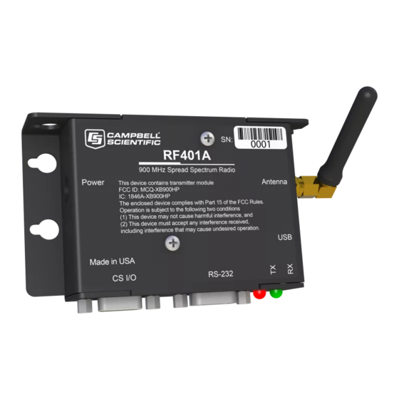
5.1.2 RF400-Series Radios The RF401A series have a choice of three communication protocol settings: Transparent, PakBus Aware, and PakBus Node. Transparent is the protocol used by the RF400, RF410, and CR205. RF401-series radios in networks that also have RF400-series radios must use the Transparent protocol setting. - Page 16 RF401A-Series Spread Spectrum Radio Radio Frequency Hopping Spread Spectrum (FHSS) Radio Transceiver Frequency RF401A: 910 to 918 MHz RF411A: 920 to 928 MHz Transmit Power Output: 5 to 250 mW, software selectable Receiver Sensitivity: –109 dBm Channel Capacity: 7 hop sequences share 25 frequencies RF Data Rate: 10 kbps RF Connector: Reverse Polarity SMA (RPSMA) jack, 50 Ohm unbalanced Power...
-
Page 17: Rf401A-Series Dimensions
RF401A-Series Spread Spectrum Radio FIGURE 6-1. RF401A-series dimensions... -
Page 18: Product Description
USB. To install the device driver, download the latest version of Device Configuration Utility from our website. Under Device Type, select Radio | RF401A Series. Click the Install the USB device driver link and follow the prompts. Most host USB ports will supply a sufficient amount of voltage and current for all normal operations. -
Page 19: Cs I/O
Campbell Scientific datalogger using the supplied SC12 cable. This connection is used for power and data. The CS I/O port is not a typical RS-232 connection and is specific to Campbell Scientific products. CS I/O cannot be used for radio configuration using the Device Configuration Utility. -
Page 20: Cs I/O Pinout ( 9-Pin D-Sub Male)
Sources 12 Vdc to power peripherals datalogger Serial data transmit line I = Signal into the RF401A series, O = Signal out of the RF401A series RS-232 The RS-232 port is a DCE, 9-pin female D-Sub connector used to for connecting the radio to the RS-232 port of a datalogger, computer, or another RS-232 device. -
Page 21: Leds
RF401A-Series Spread Spectrum Radio TABLE 7-3. RS-232 Pinout (9-PIN D-SUB FEMALE) DESCRIPTION I = Signal into the RF401A series, 0 = Signal out of the RF401A series LEDs The radios have a red LED labelled Pwr/TX and a green LED labelled RX. -
Page 22: Electrostatic Issues And Surge Protection
CAUTION In order to comply with the FCC RF exposure requirements, the RF401A series may be used only with approved antennas that have been tested with these radios and a minimum separation distance of 20 cm must be maintained from the antenna to any nearby persons. -
Page 23: Antenna Cables
USB. To install the device driver using the Device Configuration Utility, select Radio | RF401A Series under Device Type. Click the Install the USB device driver link and follow the prompts. -
Page 24: Loggernet Setup
RF401A-Series Spread Spectrum Radio LoggerNet Setup Basic Setup Start LoggerNet and open the Setup screen from the Main category of the toolbar. Start the configuration by clicking on the Add Root button. From the Add submenu make the following selections: •... - Page 25 RF401A-Series Spread Spectrum Radio With the setup tree entered, you will now need to complete the configuration of each element. Start with selecting the ComPort element at the root of the tree. Under ComPort Connection, select port labelled RF401A-Series. Set the Extra Response Time to match the Power Mode of the RF401A series.
- Page 26 RF401A-Series Spread Spectrum Radio Select the PakBusPort element in the tree, and select the PakBus Port Always Open checkbox. Set the Maximum Baud Rate to 115200.
- Page 27 RF401A-Series Spread Spectrum Radio Finally, select your datalogger in the tree. Set the PakBus Address field to the PakBus® address of your datalogger. Enter the Security Code, if security has been set up in your datalogger. Press the Apply button to save your changes. You are now ready to connect to your datalogger using the LoggerNet Connect screen.
-
Page 28: Using A Repeater
When using an RF401A-series radio as a repeater in your network, it can be entered into the LoggerNet Setup screen using the pbRouter device and entering the PakBus® address of the RF401A series in the PakBus Address field. If the repeater is the first hop from LoggerNet, it should always be shown in the network map. -
Page 29: Antenna Selection, Placement, And Mounting
RF401A-Series Spread Spectrum Radio and urban areas tend to evolve over time meaning that sources of interference may develop over time. 10.2 Antenna Selection, Placement, and Mounting Antenna selection and placement can play a large role in system performance. Often directional antennas are preferred over omnidirectional antennas when possible as RF energy can be more selectively directed and received and higher gains can be realized without the consumption of additional power. -
Page 30: Main
PakBus Node. Also ensure that PakBus Address is unique within the PakBus network. Use this setting only under special circumstances where the CSI/O port is connected to another Campbell Scientific peripheral configured for Modem Enable (ME) through an A100 Null Modem Adapter. The... -
Page 31: Sdc Address
RF401A-Series Spread Spectrum Radio 11.1.2 SDC Address Specifies the CS I/O port SDC address when Active Interface is set as CS I/O SDC. 11.1.3 RS-232 Baud Rate Specifies the baud rate that will be used on the RS-232 port when Active Interface is set as RS-232. -
Page 32: Rf Hop Sequence
RF401A-Series Spread Spectrum Radio 11.1.5 RF Hop Sequence Specifies the radio channel hop sequence. This setting must match in all radios in the same RF network. This setting can also be used to prevent radios in one RF network from listening to transmissions of another. 11.1.6 RF Network Specifies the RF network. -
Page 33: Retry Level
RF401A-Series Spread Spectrum Radio Typical Avg. Power Current Mode Draw Description The radio receiver is turned on every 0.5 seconds for 100 milliseconds to look for RF activity. The radio transmits a 700 millisecond wakeup header with the first < 2 mA transmission occurring after a period of RF inactivity. -
Page 34: Radio Tx Power Level
RF401A-Series Spread Spectrum Radio NOTE If the Retry Level is increased in a network with poor reception and many nodes, latency will greatly increase, sometimes to the point of non-operation if inundated with traffic. 11.1.10 Radio TX Power Level This setting specifies the power level at which the RF module transmits. Levels are approximate. -
Page 35: Central Router
Central Router. A valid setting is a single address between 1 and 4094. When set, the RF401A series will act as a branch router. Specifying a central router address can reduce the amount of PakBus® RF traffic by eliminating the exchange of neighbour lists with routers beyond the central router. -
Page 36: Received Signal Strength
RF401A-Series Spread Spectrum Radio 11.3.4 Received Signal Strength Indicates the signal strength of the last packet received addressed to this radio and with a valid CRC. The range of values reported, generally between 6 and 54, represent the approximate range from –110 dBm to –35 dBm with each value representing a little less than 2 dB. -
Page 37: Retransmit Failures
PakBus Graph (RF401A must be running OS Version OBJ30596V05.obj or greater) – The RF401A series must be configured as a PakBus node using DevConfig. Under the Main tab, set the Protocol to PakBus Node. This setting makes the RF401A an independent device in the network. -
Page 38: Rs-232 Stop Bits
11.3.14 AT Command Mode Timeout Specifies the amount of time (in tenths of seconds) that must elapse with no activity on the RS-232 interface before the RF401A series exits command mode automatically. 11.3.15 Net Address Mask Specifies the network portion of the address mask. -
Page 39: Part 15 Fcc Compliance Warning
Appendix A. Part 15 FCC Compliance Warning Changes or modifications to the RF401A-series radio systems not expressly approved by Campbell Scientific could void the user’s authority to operate this product. Note: This equipment has been tested and found to comply with the limits for a Class B digital device, pursuant to part 15 of the FCC Rules. -
Page 41: Distance Vs. Antenna Gain, Terrain, And Other Factors
Gain, Terrain, and Other Factors B.1 Introduction The communication distance you can expect to obtain using the RF401A series depends on a number of factors that are unique to every installation. These unique factors are the path of propagation, relative antenna elevations, and the link budget. -
Page 42: How Far Can You Go
In some cases, an in-line RF amplifier may be used to provide additional system gain, but this is rare and not typical of Campbell Scientific installations. Losses derive from the attenuation of the RF signal as it propagates through the transmission lines (coaxial cables, surge suppressor, etc.) connecting the... -
Page 43: Transmitter Power
(Pt) and transmitter power in dBm (Ptx) is: Ptx (in dBm) = 10 log (Pt) with Pt expressed in mW TABLE B-1. Transmitter Power Transmitter Power (Pt) (milliWatts) 5 (RF401A series minimum) 250 (RF401A series maximum) 1000 5000 B.2.4 Cable Loss Cable loss is a function of cable type, length, and frequency and is usually specified as attenuation (dB) per 100 ft. -
Page 44: Antenna Gain
(decibels of gain relative to a dipole). The relationship is: dBi = dBd + 2.15 Some antennas that are FCC approved for use with the RF401A series are: TABLE B-4. Antenna Gain of Recommended Antennas CSI Part Mfg. -
Page 45: Receiver Sensitivity
Appendix B. Distance vs. Antenna Gain, Terrain, and Other Factors B.2.6 Receiver Sensitivity Receiver sensitivity is usually specified in dBm for a specific bit error rate (BER). The transceiver module used in the RF401A series is specified at –109 dBm at ~10 –4 raw BER. - Page 46 Appendix B. Distance vs. Antenna Gain, Terrain, and Other Factors and interferes with the main signal. This phenomenon gives rise to the 2-Ray Multipath Propagation Model for estimating real world distances. The path geometry defined by the relative elevations of the antennas and the distance between the antennas is a significant factor in determining the degree of interference from the reflected wave.
-
Page 47: Examples
Appendix B. Distance vs. Antenna Gain, Terrain, and Other Factors B.4 Examples Some examples will help illustrate the trade-offs in a link analysis. These examples will all use the RF401A-series 900 MHz radio at maximum transmitter power, and will use –109 dBm as the required power level at the radio receiver. -
Page 48: Fade Margin (Db) Vs. Distance For 2-Ray Propagation Model In
Appendix B. Distance vs. Antenna Gain, Terrain, and Other Factors Using the Lpath values from TABLE B-8, gives: TABLE B-9. Fade Margin (dB) vs. Distance for 2-Ray Propagation Model in Example #1 Path Type 2 mi. 4 mi. 6 mi. 8 mi. - Page 49 Appendix B. Distance vs. Antenna Gain, Terrain, and Other Factors Fade margin = 149 – Lpath Using the Lpath values from TABLE B-10, gives: TABLE B-11. Fade Margin (dB) vs. Distance for 2-Ray Propagation Model in Example #2 Path Type 2 mi.
- Page 50 Appendix B. Distance vs. Antenna Gain, Terrain, and Other Factors B-10...
- Page 52 Santo Domingo, Heredia 40305 SOUTH AFRICA COSTA RICA • cleroux@csafrica.co.za • info@campbellsci.cc www.campbellsci.co.za www.campbellsci.cc Campbell Scientific Southeast Asia Co., Ltd. Campbell Scientific Ltd. 877/22 Nirvana@Work, Rama 9 Road Campbell Park Suan Luang Subdistrict, Suan Luang District 80 Hathern Road Bangkok 10250...
Need help?
Do you have a question about the RF401A Series and is the answer not in the manual?
Questions and answers