Table of Contents
Advertisement
Quick Links
Advertisement
Table of Contents

Related Manuals for Draper MS210C


Summary of Contents for Draper MS210C
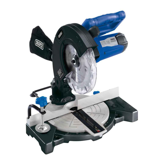
- Page 1 INSTRUCTIONS FOR 1100W 230V 210mm Mitre Saw Stock No.21307 Part No.MS210C...
-
Page 2: Title Page
Commercial copying, redistribution, hiring or lending is prohibited. No part of this publication may be stored in a retrieval system or transmitted in any other form or means without written permission from Draper Tools Limited. In all cases this copyright notice must remain intact. -
Page 3: Table Of Contents
CONTENTS 2.1 CONTENTS PAGE CONTENT PAGE TITLE PAGE INTRODUCTION ....................2 REVISION HISTORY....................2 UNDERSTANDING THIS MANUAL ...............2 COPYRIGHT NOTICE....................2 CONTENTS CONTENTS ......................3 GUARANTEE GUARANTEE ......................4 INTRODUCTION SCOPE ........................5 SPECIFICATION ......................5 HANDLING & STORAGE ..................5 HEALTH & SAFETY INFORMATION GENERAL SAFETY INSTRUCTIONS FOR POWER TOOL USE .........6-7 ADDITIONAL SAFETY INSTRUCTIONS FOR MITRE SAWS ........8 ADDITIONAL SAFETY INSTRUCTIONS FOR CIRCULAR SAW BLADES ....9 CAUTION: RISK OF ELECTRIC SHOCK. -
Page 4: Guarantee
This guarantee applies in lieu of any other guarantee expressed or implied and variations of its terms are not authorised. Your Draper guarantee is not effective unless you can produce upon request a dated receipt or invoice to verify your proof of purchase within the guarantee period. -
Page 5: Introduction
4.1 SCOPE This machine is designed to cut wood. Any other application is considered mis-use. 4.2 SPECIFICATION Stock no ........................... 21307 Part no ..........................MS210C Motor: Rated voltage ........................230V~ Rated frequency ......................... 50Hz Rated input........................1100W Revolutions per minute (no load) ................5500min Blade diameter ........................ -
Page 6: Health & Safety Information
HEALTH & SAFETY INFORMATION 5.1 GENERAL SAFETY INSTRUCTIONS FOR POWER TOOL USE When using any type of power tool there are steps that should be taken to make sure that you, as the user, remain safe. Common sense and a respect for the tool will help reduce the risk of injury. Read the instruction manual fully. - Page 7 HEALTH & SAFETY INFORMATION Wear personal protective equipment (PPE). Dust, noise, vibration and swarf can all be dangerous if not suitably protected against. If the work involving the power tool creates dust or fumes; wear a dust mask. Vibration to the hand, caused by operating some tools for longer periods must be protected against.
-
Page 8: Additional Safety Instructions For Mitre Saws
HEALTH & SAFETY INFORMATION Have this tool repaired by a qualified person. This tool is designed to conform to the relevant international and local standards and as such should be maintained and repaired by someone qualified; using only original parts supplied by the manufacturer: This will ensure the tool remains safe to use. -
Page 9: Additional Safety Instructions For Circular Saw Blades
HEALTH & SAFETY INFORMATION 5.3 ADDITIONAL SAFETY INSTRUCTIONS FOR CIRCULAR SAW BLADES Safe Working Practice Maximum speed - The maximum speed marked on the tool shall not be exceeded. Where stated, the speed range shall be adhered to. Circular saw blades - Circular saw blades, the bodies of which are cracked, shall be scrapped (repairing is not permitted). -
Page 10: Caution: Risk Of Electric Shock. Do Not Open
HEALTH & SAFETY INFORMATION 5.5 CAUTION: RISK OF ELECTRIC SHOCK. DO NOT OPEN. Caution: Risk of electric shock. Do not open. This appliance is supplied with a moulded 3 pin mains plug for your safety. The value of the fuse fitted is marked on the pin face of the plug. -
Page 11: Technical Description
TECHNICAL DESCRIPTION 6.1 IDENTIFICATION Workpiece vice Base stabiliser Bevel locking knob Dust bag Plunge handle. Plunge release lever Lower blade guard Mitre lock knob Fence Table Mitre pointer Table insert On/Off trigger Saw head locking pin Depth stop Bevel pointer 0º... -
Page 12: Unpacking & Checking 7.1 Packaging
Lay the contents out and check them against the parts shown below. If any part is damaged or missing; please contact the Draper Helpline (the telephone number appears on the Title page) and do not attempt to use the machine. -
Page 13: Preparing The Mitre Saw
PREPARING THE MITRE SAW NOTE: Remove the plug from the socket before carrying out adjustment, servicing or maintenance. BENCH MOUNTING NOTE: Securing the mitre saw. For safe working practice the saw must be mounted on a secure level surface. Using the holes in the base and four suitable bolts (not supplied) to fix the saw down. -
Page 14: Saw Head Locking Pin
PREPARING THE MITRE SAW SAW HEAD LOCKING PIN - FIG. 3 FIG.3 The saw head is locked in the down position for transport purposes and should be returned to this position when not in use. To release the saw head slightly press down on the saw head before pulling out the locking pin NOTE: The pin does not detach from the saw. -
Page 15: Dust Extraction
PREPARING THE MITRE SAW DUST EXTRACTION - FIG. 7 FIG.7 The saws come supplied with a cloth dust bag Pinch the spring clip open and slide onto extraction port, release clip slowly. Empty the dust bag regularly or when full. When cutting large pieces of material or cutting for a longer period, exchange the dust bag with a dust extractor to allow more efficient removal of harmful airborne dust particles. -
Page 16: Checking The Table To Blade Alignment
PREPARING THE MITRE SAW 8.10 CHECKING THE TABLE TO BLADE FIG.10 ALIGNMENT - FIGS. 10 - 12 NOTE: Remove the plug from the socket before carrying out adjustment, servicing or maintenance. Lower and lock the saw head. Set the mitre and bevel angles to zero and lock. -
Page 17: Check The Fence To Blade Alignment
PREPARING THE MITRE SAW 8.11 CHECK THE FENCE TO BLADE FIG.13 ALIGNMENT - FIG. 13 NOTE: Remove the plug from the socket before carrying out adjustment, servicing or maintenance. Lower and lock the saw head. Set the mitre and bevel angles to zero and lock. Place a small engineers square flat against the fence and the blade making sure that the square contacts the flat side of the blade and not the teeth. -
Page 18: Blade Replacement
PREPARING THE MITRE SAW 8.13 BLADE REPLACEMENT - FIGS. 15 - 16 FIG.15 NOTE: Remove the plug from the socket before carrying out adjustment, servicing or maintenance. With the saw head in the raised position. Press the spindle lock button and with the 6mm hex. -
Page 19: Mitre Cut
OPERATING THE MITRE SAW MITRE CUT - FIG. 17 When a mitre cut is required, move the saw to the desired angle. Do not stand in front of the saw table. Move with the handle to the mitre angle to make the cut. -
Page 20: Cutting Curved Or Warped Material
OPERATING THE MITRE SAW CUTTING CURVED OR WARPED FIG.20 MATERIAL - FIGS. 20 - 21 Before cutting a workpiece, check to make sure it is flat. If it is curved or warped, the workpiece must be positioned and cut as illustrated. Do not position workpiece incorrectly or try to cut the workpiece without the support of the fence. -
Page 21: Workpiece Support
OPERATING THE MITRE SAW WORKPIECE SUPPORT Long pieces need extra supports. The supports should be placed along the workpiece so the workpiece does not sag and the hand holding the workpiece is positioned 4" or more from the blade path. The support should let the workpiece lay flat on the base and worktable during the cutting operation. -
Page 22: Glossary Of Terms For Woodworking
10. GLOSSARY OF TERMS FOR WOODWORKING ARBOR/SPINDLE MITRE CUT The shaft on which a cutting tool is An angle cutting operation made across the mounted. width of the workpiece. BEVEL CUT RESIN An angle cutting operation made through A stick, sap based substance that has dried the face of the workpiece. -
Page 23: Maintenance
If the replacement of the supply cord is WARNING: To avoid injury from unsafe necessary, this has to be done by the accessories, use only Draper accessories. manufacturer or his agent in order to avoid PROHIBITED ACCESSORIES a safety hazard. -
Page 24: Troubleshooting
12. TROUBLESHOOTING NOTE:Remove the plug from the socket before carrying out adjustment, servicing or maintenance. PROBLEM POSSIBLE CAUSE REMEDY • Fuse. • Replace time delay fuse or reset Motor does not circuit breaker. start. • Have brushes replaced by an •... -
Page 25: Optional Accessories
13. OPTIONAL ACCESSORIES 13.1 OPTIONAL ACCESSORIES Stock No. Part No. Diameter Bore Teeth Reducing Bushes Supplied Description 09476 CSB210P 210mm 30mm 16mm Rip and Cross Cut 09477 CSB210P 210mm 30mm 16mm Cross Cut 09478 CSB210P 210mm 30mm 16mm Cross Cut... -
Page 26: Explanation Of Symbols
14. EXPLANATION OF SYMBOLS 14.1 EXPLANATION OF SYMBOLS Warning! Warning! Read the instruction manual Do not wear loose clothing. Warning! Warning! Wear suitable Keep hands away for blade. eye/face protection. Warning! Warning! Wear dust mask. Wear ear defenders. Warning! Disable the machine Double insulated. -
Page 27: Disposal
15. DISPOSAL 15.1 DISPOSAL - At the end of the machine’s working life, or when it can no longer be repaired, ensure that it is disposed of according to national regulations. - Contact your local authority for details of collection schemes in your area. In all circumstances: •... - Page 28 YOUR DRAPER STOCKIST RDMC0816 drapertools.com...
Need help?
Do you have a question about the MS210C and is the answer not in the manual?
Questions and answers