
Related Manuals for Saunier Duval 050 EKI


Summary of Contents for Saunier Duval 050 EKI
- Page 1 WITH AXIALS FAN OUTDOOR UNITS Installation Manual CEILING-FLOOR, CASSETTE AND DUCTS...
- Page 2 These items must be fitted and used in accordance with the Regulations and Standards in effect for cooling, electrical and mechanical installations for where they are to be fitted. Having a policy of continuous product improvement, Saunier Duval reserves the right to modify the specifications, giving no prior warning.
-
Page 3: Safety Regulations
Incorrect voltage may cause fires or other adjacent building is prohibited. problems. The appliance is to be installed, maintained Always use original Saunier Duval spare and repaired by qualified staff pursuant to parts. Do not use components removed the demands of the guidelines, current... - Page 4 065 EFI 645 085 EFI 645 1.250 1.168 105 EFI 645 1.750 1.668 Units in mm 2.2 CASSETTE INDOOR UNITS (EKI) Model 050 EKI 580 065 EKI 580 085 EKI 580 1089 1205 105 EKI 130 EKI Units in mm...
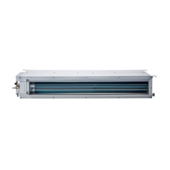
- Page 5 2- DIMENSIONS 2.3 DUCTS INDOOR UNITS (EDI) MODELS 050 EDI 1.000 1.040 065 EDI 1.000 1.040 085 EDI 1.010 1.050 105 EDI 1.210 1.100 1.150 1.250 130 EDI 1.310 1.100 1.250 1.350 180 EDI 1.400 1.047 1.305 1.405 Units in mm It’s advisable to respect the specified minimum distances around the...
- Page 6 2- DIMENSIONS 2.4 INDOOR UNITS (EZI) MODELS 230 EZI 1.660 Units in mm It’s advisable to respect the specified minimum distances around the apparatus. Units in mm Is very important the positioning of a siphon in each water-drainage.
-
Page 7: Outdoor Units
2- DIMENSIONS 2.5 OUTDOOR UNITS Model Models 050 - 065 Liq. 3/8" 050 / 065 Liq. 3/8" 3/4" 5/8" Models 105 - 105T Model 105 / 105T / 130 120 M2 Liq. 3/8" 1/2" 3/4" 3/4" Model Liq. 1/2" 7/8"... - Page 8 2- DIMENSIONS 2.5 OUTDOOR UNITS Model Liq. 5/8" Gas 1 1/8" Units in mm 2.5.1 OUTDOOR UNIT LOCATION Units in mm Units in mm Location for a correct air flow...
-
Page 9: Indoor Unit Installation
3- INDOOR UNIT INSTALLATION 3.1 CEILING-FLOOR: INDOOR UNITS B.2 INSTALLING DRAIN HOSE 3.1.1 INSTALLATION PROCEDURE Be sure to arrange the drain hose so that it is A. PREPARING INDOOR UNIT INSTALLATION levelled lower than the drain port of the indoor unit. -
Page 10: Installing Indoor Unit
3- INDOOR UNIT INSTALLATION C.2 DRILLING HOLES FOR ANCHOR BOLTS AND INSTALLING THE ANCHOR BOLTS Always check that the drain cap is installed to the unused drain port and is fastened With a concrete drill, with the nylon fastener. If the drain cap is drill four 3/8”... -
Page 11: Cassette: Indoor Unit
3- INDOOR UNIT INSTALLATION 3.2 CASSETTE: INDOOR UNIT 3.2.1 INSTALL THE INDOOR UNIT IN A POSI- TION: - Ensure there is sufficient space around the unit to service it. - Having sufficient strength to carry the weight of the indoor unit. - Where the inlet and outlet grilles are not obstruc- ted and the conditioned air is able to blow all over the room. -
Page 12: Interconnecting Wiring
3- INDOOR UNIT INSTALLATION - Using level guide, line up the unit with a spirit - Line up the unit to the supporting bars of the level, and keep dimension between the fiber false ceiling tightening the nuts and counternuts glass body and the lower part of the false cei- of the threaded rods. -
Page 13: Fresh Air Renewal And Branch Ducting
3- INDOOR UNIT INSTALLATION 3.2.4 FRESH AIR RENEWAL AND BRANCH DUCTING - The side opening allows separate ductwork to - Install your flanges and conduits to casing. Con- be installed for outside air intake and branch duits can be flexible polyester with spring core or ducting. -
Page 14: Initial Check
3- INDOOR UNIT INSTALLATION 3.3 DUCTS: INDOOR UNIT 3.3.3 INDOOR UNIT INSTALLATION 3.3.1 INITIAL CHECK - Insert and screw down a nut on each supporting rod. - Install indoor unit allowing for enough clearance - Lift the indoor unit and insert the rods in the around the unit so there is room for handling and holes provided on the mounting brackets. -
Page 15: Outdoor Unit Installation
4- OUTDOOR UNIT INSTALLATION 4.1. OUTDOOR UNIT When the outdoor unit will be exposed to strong Install de outdoor unit in a place where it will be wind, fasten it with bolts at the places indicated free from being dirty or getting by rain as much by the arrows. -
Page 16: Pipe Length
4- OUTDOOR UNIT INSTALLATION 4.3 PIPE LENGTH ORIGIN DISTANCE IN LINEALS m. Models Load R-407C (kg) Lines (‘‘) 15 m (4 curves) 20 m (6 curves) 30 m (8 curves) 50 m (6 curves) Max. Height (m) Cool Heat Liq. % Aprox. R-407C Oil % Aprox. R-407C Oil % Aprox. R-407C Oil % Aprox. R-407C Oil Over Under 5/8”... -
Page 17: Maintenance Instructions
4- OUTDOOR UNIT INSTALLATION 4.4 CHECKING THE PIPE CONNECTIONS FOR 4.7 POWER GAS LEAKING (1) The rate voltage of this product is monophase (230V/1Ph/50 Hz) or triphase (400V/3Ph/50Hz). (2) Perform wiring work in accordance with stan- - For both the indoor and outdoor unit sides, check dards so that the room air conditioner can be the joints for gas leaking by the use of a gas operated safely and positively. -
Page 18: Wiring Diagrams
5- WIRING DIAGRAMS 105T / 130 / 180 050 / 065 / 085 / 105 120 M2 Riht section mm Power Supply* Up to 25 m. Magnetothermique Differential MODELS (V/Ph/Hz) Type D 1Δn Manoeuvre Force 230/1/50 10 A 0,03 A 230/1/50 20 A 0,03 A... - Page 19 5- WIRING DIAGRAMS The installation of electric assault to the machine should have a Bipolar or Tetrapolar switch according to machine model, (monophase or treephase), of at least 3 mm of separation among contacts (norm EN-60335-2-40). To ensure that this appliance complies with EN-61000-3-11 standard verify that the service current supply capacity is >100A at the interface point.
-
Page 20: Control Units Diagrams
6- CONTROL UNITS DIAGRAMS 6.1 CEILING-FLOOR INDOOR UNITS Heater Relay Deflector Relay ON-OFF Switch Conn. 4-Way Valve Relay M-L-H Fan Relay TFULL Inner Jumper Float Outdoor Unit Fan Relay COMP Compressor Relay ROOM Room Temp. Sensor Condensation Pump Relay Fuse I. - Page 21 6- CONTROL UNITS DIAGRAMS 6.3 DUCTS INDOOR UNITS Heater Relay Deflector Relay ON-OFF Switch Conn. 4-Way Valve Relay M-L-H Fan Relay TFULL Inner Jumper Float Outdoor Unit Fan Relay COMP Compressor Relay ROOM Room Temp. Sensor Condensation Pump Relay Fuse I.
- Page 22 6- CONTROL UNITS DIAGRAMS 6.5 OUTDOOR UNITS (085 ECO/EHO) 230 w 230 w 230 w CON1 CON2 CON3 R S T VDR2 VDR1 TRC1 TRC1 TRC3 TRC2 PRESOS. TERMOS. V.4.V. LED2 LED3 LED4 LED5 LED1 IC10 LED6 LED7 LED8 BOBINA TEST SOLEN.
Need help?
Do you have a question about the 050 EKI and is the answer not in the manual?
Questions and answers