
Subscribe to Our Youtube Channel
Related Manuals for Anybus Communicator PROFINET IRT


Summary of Contents for Anybus Communicator PROFINET IRT
- Page 1 ® Anybus Communicator ™ PROFINET ® IRT (2.32) USER MANUAL SCM-1202-033-EN 1.1 ENGLISH...
- Page 2 HMS Industrial Networks AB has intellectual property rights relating to technology embodied in the product de- scribed in this document. These intellectual property rights may include patents and pending patent applications in the USA and other countries. Anybus ® is a registered trademark of HMS Industrial Networks AB. All other trademarks mentioned in this document are the property of their respective holders.
-
Page 3: Table Of Contents
Network Configuration ....................17 General........................17 Basic TCP/IP Concepts ....................18 TCP/IP Configuration ....................19 Web Pages........................22 PROFINET Data Exchange..................23 Overview........................23 GSD File ........................23 Data Representation (IO Data and Record Data) ............24 ® ® Anybus Communicator ™ PROFINET IRT (2.32) User Manual SCM-1202-033-EN 1.1... - Page 4 Table of Contents Anybus Configuration Manager ................25 Main Window.......................25 Basic Settings......................28 Nodes .........................32 Transactions (Master Mode and Generic Data Mode) .............34 Frame Objects (Master Mode & Generic Data Mode) ............39 Commands (Master Mode & Generic Data Mode)............46 Services (DF1 Master Mode) ..................50 Subnetwork Monitor .....................54...
-
Page 5: Preface
Preface 3 (66) Preface About This Document This document describes how to install and configure the Anybus Communicator PROFINET IRT (2.32) gateway For additional related documentation and file downloads, please visit www.anybus.com/support. Document history Version Date Description 2017-02-07 First release... -
Page 6: Document Conventions
Caution This instruction must be followed to avoid a risk of personal injury. WARNING This instruction must be followed to avoid a risk of death or serious injury. ® ® Anybus Communicator ™ PROFINET IRT (2.32) User Manual SCM-1202-033-EN 1.1... -
Page 7: Description
Description Introduction Anybus Communicator PROFINET IRT (2.32) is intended for connecting non-networked indus- trial devices and equipment to a PROFINET network. It performs an intelligent protocol conver- sion and presents the serial data to the PROFINET IO Controller as easily processed I/O data. -
Page 8: Basic Operation
6 (66) Basic Operation Anybus Communicator PROFINET IRT (2.32) is designed to exchange data between a serial subnetwork and a higher level network. It does not have a fixed protocol for the subnetwork and can be configured to handle almost any form of serial communication. -
Page 9: Data Exchange Model
The data exchanged on the subnetwork and the data exchanged on the higher level network re- side in the same internal memory in the Anybus Communicator. In order to exchange data with the subnetwork, the higher level network simply reads and writes data to memory locations that have been specified in Anybus Configuration Manager. - Page 10 2.3.3 Data Exchange Example In this example, a temperature regulator on the serial subnetwork exchanges data with a PLC on the higher level network via the internal memory buffers in the Anybus Communicator. PLC (PROFINET IO Controller) PLC Memory (Inputs)
-
Page 11: Subnetwork Protocol
Master Mode In this mode, the Anybus Communicator acts as a master on the subnetwork and serial commu- nication takes place in query-response fashion. The nodes on the network are not permitted to issue messages until they are addressed by the gateway. - Page 12 10 (66) DF1 Master Mode In this mode the Anybus Communicator act as a DF1 protocol master on the subnetwork. Serial communication takes place in query-response fashion. The nodes on the network are not per- mitted to issue messages until they are addressed by the gateway.
-
Page 13: Installation
These are the basic steps for installing Anybus Communicator gateways. Depending on the fieldbus network type there may also be configuration switches, etc. on the Anybus Communicator that need setting. See the following sections in this document for more information. -
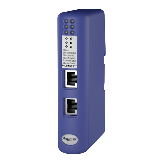
Page 14: Connectors And Indicators
Push down to mount or remove Remove from DIN rail Push the unit gently downwards on the rail. Pull the bottom end of the unit free of the rail and remove it. ® ® Anybus Communicator ™ PROFINET IRT (2.32) User Manual SCM-1202-033-EN 1.1... -
Page 15: Serial Subnetwork Interface
To avoid reflections on the serial lines, it is important to properly terminate the subnetwork by placing termination resistors between the serial receivers near the end nodes. The resistor value should ideally match the characteristic impedance of the cable, typically 100–120 Ω. ® ® Anybus Communicator ™ PROFINET IRT (2.32) User Manual SCM-1202-033-EN 1.1... -
Page 16: Profinet Interface
PC Connector (RJ11) The RJ11 type 4P4C modular connector can also be referred to as RJ9. RJ11 (Communicator) DE-9 (PC) RS-232 Rx RS-232 Tx Fig. 14 Configuration cable ® ® Anybus Communicator ™ PROFINET IRT (2.32) User Manual SCM-1202-033-EN 1.1... -
Page 17: Led Indicators
Running, one or more transaction errors Transaction error/timeout, or subnet stopped 6 - Device Status No power Green Initializing Green, flashing Running Bootloader mode Alternating red/green Configuration error ® ® Anybus Communicator ™ PROFINET IRT (2.32) User Manual SCM-1202-033-EN 1.1... - Page 18 200 ms 1000 ms Quadruple flash 200 ms 200 ms 200 ms 200 ms 200 ms 200 ms 200 ms 1000 ms Fig. 15 LED indicator timing intervals ® ® Anybus Communicator ™ PROFINET IRT (2.32) User Manual SCM-1202-033-EN 1.1...
-
Page 19: Network Configuration
IPconfig. DCP (Discovery and Control Protocol) Anybus Communicator PROFINET IRT (2.32) supports DCP, which allows a PROFINET IO Controller or Supervisor to change the network settings during runtime. The settings applied through DCP will replace the currently stored settings. -
Page 20: Basic Tcp/Ip Concepts
The default gateway address in the TCP/IP settings of your product specifies the IP address of the gateway or router on the local network. ® ® Anybus Communicator ™ PROFINET IRT (2.32) User Manual... -
Page 21: Tcp/Ip Configuration
IPconfig is a Windows-based tool for configuration of TCP/IP settings in HMS devices. The tool will detect all compatible and active HMS devices on the local network. Download IPconfig from www.anybus.com/support. Unpack the contents of the zip archive and run the installer program. - Page 22 Password field, then enter the new password in the New password field. For security reasons the default password should always be changed. Click on Set to save the new settings. The device will reboot automatically. ® ® Anybus Communicator ™ PROFINET IRT (2.32) User Manual...
- Page 23 Select the device and configure it to use static IP addressing instead of DHCP. Disable the internal DHCP server. Do not enable the internal DHCP server if there is already an active DHCP server on the network. ® ® Anybus Communicator ™ PROFINET IRT (2.32) User Manual SCM-1202-033-EN 1.1...
-
Page 24: Web
IP address of the interface. Module Overview Fig. 19 Overview tab Provides basic information about the Anybus Communicator including the serial number and the installed firmware version. Network Status Fig. 20 Status tab Displays an overview of the current network status. -
Page 25: Profinet Data Exchange
All PROFINET devices are associated with an XML-based GSD file. This file contains informa- tion about the basic capabilities and configuration options of the device. The latest version of the GSD file for Anybus Communicator PROFINET IRT (2.32) can be downloaded from www.anybus.com/support. -
Page 26: Data Representation (Io Data And Record Data)
Second byte of the Output parameter area … 214Fh Last byte of the Output parameter area The Control Word and Status Word and the Live List are not considered in this example. ® ® Anybus Communicator ™ PROFINET IRT (2.32) User Manual SCM-1202-033-EN 1.1... -
Page 27: Anybus Configuration Manager
A hierarchic tree view of the configuration, divided into three main sections: Fieldbus Communication settings for the fieldbus network interface Communicator RS232/422/485 General settings for the Anybus Communicator Subnetwork Communication settings for the serial subnetwork Select an entry to display its available parameters in the Parameter List. Right-click on the entry to show additional options. - Page 28 Show/hide the status bar at the bottom of the main window. 6.1.4 Help Menu About Shows general information about Anybus Configuration Manager and the currently connected Anybus Communicator. A help system is not included in this version of Anybus Configuration Manager. ® ® Anybus Communicator ™...
- Page 29 Manager without saving the configuration. Show Wizard ... Open a wizard when creating a new configuration Select Language The language to use in Anybus Configuration Manager. The program must be restarted for the new language seting to become active. Module Size of logbuffer The number of entries logged in each direction by the Data Logger.
-
Page 30: Basic Settings
6.2.1 Fieldbus Settings During start-up the fieldbus interface of the Anybus Communicator is initialized to fit the configu- ration created in Anybus Configuration Manager. Optionally, some initialization parameters can be set manually to provide better control over how the data shall be treated by the module. - Page 31 Anybus Configuration Manager 29 (66) 6.2.2 Communicator Parameters Fig. 26 Communicator parameters Interface The physical interface type of the subnetwork. Cannot be changed from Serial. Control/Status Word Enabled Enables the Control and Status Registers. The Data Valid bit in the Control Register must be set to start the subnetwork communication.
- Page 32 Anybus Configuration Manager 30 (66) 6.2.3 Subnetwork Parameters Fig. 27 Subnetwork parameters Communication The values that can be selected depend on the selected protocol mode. Possible values Parameter Description Bitrate (bits/s) Selects the bit rate 1200 to 57600 Data bits...
- Page 33 Anybus Configuration Manager 31 (66) Timing – Message delimiter This parameter is available in Master Mode and Generic Data Mode. • Master Mode Message delimiter specifies the time that separates two messages in steps of 10 ms. If set to 0 (zero), the standard Modbus delimiter of 3.5 characters will be used. The actual time in ms will then be calculated automatically based on the communication settings.
-
Page 34: Nodes
6.3.1 General A node in Anybus Configuration Manager represents a single device on the network. Although the gateway does not feature a scan list in the traditional sense, all nodes and their transactions will be processed in the order they have been defined in the configuration. - Page 35 Anybus Configuration Manager 33 (66) 6.3.4 Node Context Menu Fig. 31 Node context menu Right-click on a node to open a context menu with additional commands for managing or adding nodes. Node Context Menu (right click) Menu Command Description Copy...
-
Page 36: Transactions (Master Mode And Generic Data Mode)
6.4.1 General Transactions in Anybus Configuration Manager are representations of the actual serial tele- grams exchanged on the serial subnetwork. Although the gateway does not feature a scan list in the traditional sense, all nodes and their transactions will be processed in the order they have been defined in the configuration. - Page 37 Anybus Configuration Manager 35 (66) 6.4.3 Query/Broadcast Transactions (Master Mode) Fig. 33 Transaction parameters Query/Broadcast Transaction Parameters Description Parameter Minimum time between How long the gateway should wait after transmitting a broadcast transac- broadcasts (10 ms) tion before processing the next entry in the scanlist.
- Page 38 Anybus Configuration Manager 36 (66) Query/Broadcast Transaction Parameters (continued) Description Parameter Update mode Specifies when the transaction shall be sent to the slave. Cyclically = The transaction is issued cyclically at the interval specified in the Update time parameter. On data change = The data area is polled for changes at the time interval defined by the Update time parameter.
- Page 39 Anybus Configuration Manager 37 (66) 6.4.5 Produce Transactions (Generic Data Mode) Fig. 35 Parameters Description Parameter Offline options for fieldbus The action to take for this transaction if the higher level network goes off- line. This affects the data that is sent to the subnetwork.
- Page 40 Anybus Configuration Manager 38 (66) 6.4.6 Consume Transactions (Generic Data Mode) Fig. 36 Parameters Parameter Description Offline options for subnetwork The action to take for this transaction if the subnetwork goes offline. This affects the data that is sent to the higher level network.
-
Page 41: Frame Objects (Master Mode & Generic Data Mode)
Anybus Configuration Manager 39 (66) Frame Objects (Master Mode & Generic Data Mode) 6.5.1 General Each transaction consists of Frame Objects which make up the serial telegram frame. Each frame object specifies how the gateway shall interpret or generate a particular part of the telegram. - Page 42 Anybus Configuration Manager 40 (66) 6.5.3 Constant Objects (Byte, Word, Dword) Fig. 40 Constant object Constant Objects contain a fixed value of a Byte (8 bits), Word (16 bits) or DWord (32 bits). • Produce and Query Transactions The gateway will send the value as-is without processing.
- Page 43 Anybus Configuration Manager 41 (66) 6.5.4 Limit Objects (Byte, Word, Dword) Fig. 41 Limit object Limit Objects define a value range between a maximum and a minimum value. The two values can be given as a Byte (8 bits), Word (16 bits) or DWord (32 bits).
- Page 44 Anybus Configuration Manager 42 (66) 6.5.5 Data Object Fig. 42 Data object Data Objects are used to present raw data. • Produce and Query Transactions The specified data block is forwarded from the higher level network to the subnetwork. •...
- Page 45 Anybus Configuration Manager 43 (66) 6.5.6 Variable Data Object Fig. 43 Variable data object Each transaction can only contain one variable data object. This object is similar to the Data Object, except that it has no predefined length. Instead, an...
- Page 46 Anybus Configuration Manager 44 (66) Variable Data Object Parameters Description Parameter Byte Swap No swapping No swapping will be performed on the data Swap 2 bytes A, B, C, D becomes B, A, D, C Swap 4 bytes A, B, C, D becomes D, C, B, A...
- Page 47 Anybus Configuration Manager 45 (66) 6.5.7 Checksum Object Fig. 45 Checksum object Most serial protocols features some way of verifying that the data has not been corrupted during transfer. The Checksum Object calculates and includes a checksum in a transaction.
-
Page 48: Commands (Master Mode & Generic Data Mode)
SlaveAddress parameter. These parameters cannot be edited directly and will be greyed out in the parameter section of Anybus Configuration Manager. In Master Mode, commands for the most common Modbus RTU functions have been prede- fined. - Page 49 Anybus Configuration Manager 47 (66) 6.6.3 Command Editor The Command Editor is used to define new commands and edit existing ones. This makes it possible to build a library of commands, which can be stored and reused at a later stage.
- Page 50 Anybus Configuration Manager 48 (66) Editing a Command The transaction section in the Command Editor represents the transactions associated with the command. Each column represents a frame object within the transaction, and contains the fol- lowing parameters: • Query/Response/Produce/Consume Indicates the direction of the transaction.
- Page 51 Anybus Configuration Manager 49 (66) Fig. 48 Example - Modbus RTU Command Query DisplayName Slave Address Function Data Checksum ObjectType Byte Byte Data Checksum Value [SlaveAddress] User User Linked to the Retrieved from the Size and location of Checksum type...
-
Page 52: Services (Df1 Master Mode)
Services are commands that can be stored and reused. The user configures each slave with services that can be issued from the master. When the Anybus Communicator is going to exe- cute a service, it automatically chooses the appropriate DF1 command(s) used to perform the service on the selected DF1 node type. - Page 53 Anybus Configuration Manager 51 (66) Common Parameters Fig. 50 Common parameters These parameters are common to all services, but the settings are individual to each instance of a service. General Parameter Description Valid settings Offline options for fieldbus The action to take for this service if the fieldbus goes Clear offline.
- Page 54 Anybus Configuration Manager 52 (66) 6.7.2 Integrity Check This service checks that a node is up and running correctly. A telegram is sent to the node, and the node mirrors and returns the telegram. This service contains no configuration apart from the common parameters.
- Page 55 Anybus Configuration Manager 53 (66) 6.7.4 Read Data This service is used to read data from the nodes in the subnetwork. Fig. 53 Read Data service Command Parameters Description Valid settings Parameter Element Number The element number of the data file to be accessed PLC-5: 0–999...
-
Page 56: Subnetwork Monitor
Anybus Configuration Manager 54 (66) Subnetwork Monitor 6.8.1 General The Subnetwork Monitor is intended to simplify configuration and troubleshooting of the subnet- work. Its main function is to display the data allocated for subnetwork communication and detect if any area has been allocated twice (address collision). -
Page 57: Node Monitor
Anybus Configuration Manager 55 (66) Node Monitor 6.9.1 General The Node Monitor can provide valuable information when setting up the communication with the subnetwork, by allowing individual commands to be issued manually, and monitoring the re- sponse (if applicable). It also provides an overview of the memory used by a particular node. - Page 58 Anybus Configuration Manager 56 (66) 6.9.2 Operation Fig. 57 Node Monitor A: Menus and Toolbar Buttons File Exit Closes the Node Monitor Enable all transactions associated with the node Start Node Node Disable all transactions associated with the node Stop Node...
-
Page 59: Data Logger
The subnetwork traffic can be logged into a buffer. This may provide valuable information when debugging the lowest levels of the subnetwork communication. The logger is built into the gateway and is separate from Anybus Configuration Manager. This means that logging can be performed even if the gateway is disconnected from the computer. -
Page 60: Configuration Wizard
Please refer to the documentation of the respective devices for infor- mation about their serial communication requirements. If the wizard does not support a particular Modbus command required by a device, the com- mand can be specified manually as a transaction in Anybus Configuration Manager. ® ®... -
Page 61: Control And Status Registers
Control and Status Registers 6.12.1 General The Control and Status registers are disabled by default but can be enabled in Anybus Configu- ration Manager. These registers form an interface for exchanging status information between the subnetwork and the fieldbus control system. - Page 62 The Data Valid bits in the Control and Status registers are used to ensure data consistency dur- ing start-up and fieldbus offline/online transitions. If the Control/Status Word parameter in Anybus Configuration Manager is set to Enabled, the gateway will wait for the fieldbus control system to set the Data Valid bit in the Control register before it starts exchanging data on the sub-network.
- Page 63 Anybus Configuration Manager 61 (66) 6.12.4 Status Register Contents (0x000 to 0x001) Description Name Send (SR_HS_SEND) Control the handshaking towards the fieldbus control system. Confirm (SR_HS_CONFIRM) Data Valid (Master Mode and DF1 Master Mode only) Set when all transactions have been executed successfully at least once.
- Page 64 Anybus Configuration Manager 62 (66) 6.12.5 Control Register Contents (0x200 to 0x201) Description Name Confirm (CR_HS_CONFIRM) Control the handshaking towards the gateway. Send (CR_HS_SEND) Data Valid Controls data consistency. 1: Output Area valid – Exchange data on the subnetwork 0: Output Area not valid – Do not exchange data on the subnetwork...
-
Page 65: A Technical Data
Appendix A: Technical Data 63 (66) Technical Data General Specifications Model name Anybus Communicator PROFINET IRT (2.32) Order code AB7078 Dimensions (L x W x H) 120 x 75 x 27 mm Weight 150 g Operating temperature 0 to +55 °C (IEC 60068-2-1 and IEC 60068-2-2) Storage temperature -40 to +85 °C (IEC 60068-2-1 and IEC 60068-2-2) -
Page 66: B Regulatory Compliance
- EN 61000-4-4 (2012) - EN 61000-4-5 (2014) - EN 61000-4-6 (2014) The Declaration of Conformity is available at www.anybus.com/support. Disposal and Recycling You must dispose of this product properly according to local laws and regulations. Because this product contains electronic components, it must be disposed of separately from household waste. - Page 67 This page intentionally left blank...
- Page 68 last page © 2018 HMS Industrial Networks AB Box 4126 300 04 Halmstad, Sweden info@hms.se SCM-1202-033-EN 1.1.7432 / 2018-02-14...
Need help?
Do you have a question about the Communicator PROFINET IRT and is the answer not in the manual?
Questions and answers