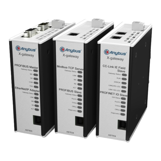
Anybus X-gateway User Manual
Hide thumbs
Also See for X-gateway:
- Installation sheet (2 pages) ,
- Network manual (14 pages) ,
- Network manual (16 pages)
Table of Contents
Advertisement
Advertisement
Table of Contents

Summary of Contents for Anybus X-gateway
- Page 1 Anybus ® X-gateway ™ USER MANUAL HMSI-27-262 3.0 ENGLISH...
-
Page 2: Intellectual Property Rights
HMS Industrial Networks AB has intellectual property rights relating to technology embodied in the product de- scribed in this document. These intellectual property rights may include patents and pending patent applications in the USA and other countries. ® Anybus X-gateway ™ User Manual HMSI-27-262 3.0... -
Page 3: Table Of Contents
Conventions ........................4 Document-specific Conventions ..................4 Description ........................5 Introduction ........................5 Data Exchange ......................6 Status and Diagnostics....................7 Controlling the X-gateway from the Network..............9 Error Handling .......................9 Data Mapping Examples....................10 Installation ........................11 DIN Rail Mounting......................11 Connectors and Indicators ....................12 Anybus Configuration Manager ................13 Introduction .........................13... - Page 4 This page intentionally left blank...
-
Page 5: Preface
Preface 3 (18) Preface About This Document This document describes the functions and general configuration of the Anybus X-gateway. Documentation and software for the specific fieldbus and Ethernet network interfaces can be downloaded from www.anybus.com/support. Related Documents Document Author Document ID... -
Page 6: Conventions
The following conventions are used specifically in this document: • Hexadecimal values are written as NNNNh (the suffix h indicates hexadecimal notation). • 16 and 32 bit values are stored in Motorola (big endian) format unless otherwise stated. ® Anybus X-gateway ™ User Manual HMSI-27-262 3.0... -
Page 7: Description
The Anybus X-gateway consists of two Anybus fieldbus or Ethernet network interface modules and an intelligent gateway platform which transfers data between the two networks. The X-gateway can be configured via a USB port using a Windows-based application, Anybus Configuration Manager. The on-board network interfaces are normally configured from the re- spective networks, using third-party configuration tools. -
Page 8: Data Exchange
The terminology and definitions used for different types of data vary between different network types. Most networks distinguish between fast, cyclical I/O data, and less time-critical acyclic data. In the Anybus X-gateway these types of data are generally referred to respectively as I/O Data and Parameter Data. -
Page 9: Status And Diagnostics
Runtime status and diagnostic information can be provided through the Status Word, which (if enabled) takes up the first two bytes of the output area (data to the network). The Status Word is disabled by default and must be enabled for each network separately through Anybus Configuration Manager. (MSB) (LSB) - Page 10 The list is assembled by the master interface and forwarded to the other network each gateway cycle. The Live List functionality is disabled by default and must be enabled for the master interface through Anybus Configuration Manager. Offset bit 0...
-
Page 11: Controlling The X-Gateway From The Network
See the Network Guide for the respective interface for more information. Error Handling If a network goes offline the X-gateway can either freeze (keep the current value) or clear (set to zero) the data from the network that has gone offline. Which action to take can be selected via Anybus Configuration Manager. -
Page 12: Data Mapping Examples
Data Mapping Examples Usage of the Control Word, Status Word and Live List affect how data is mapped to the network interfaces in the Anybus X-gateway. The following generic examples describe typical configurations. The actual representation of data on the network is highly network-specific and is described in the Network Guide for the re- spective interface. -
Page 13: Installation
Unscrew the DIN clip from the back Remove for optional DIN re tting of the unit. Refit the DIN clip to the side panel. Fig. 6 Refit the DIN clip to the side panel ® Anybus X-gateway ™ User Manual HMSI-27-262 3.0... -
Page 14: Connectors And Indicators
Communication running Communication error Red, flashing Network interface error All other LED indicators, connectors and configuration switches are specific for each network in- terface and are described in the respective Network Guide. ® Anybus X-gateway ™ User Manual HMSI-27-262 3.0... -
Page 15: Anybus Configuration Manager
Some parameters in the gateway may however need to be adjusted to suit specific networks and applications. The gateway settings are accessed via the USB port of the X-gateway using the Windows- based application Anybus Configuration Manager. -
Page 16: Setup
Fig. 11 Select a connection Select the connection to use for the X-gateway and click on OK. The USB connection will be named Anybus Serial Connection. There is normally no need to configure the connection unless you are connected to more than one X-gateway. -
Page 17: A Technical Data
Mechanical rating IP20, NEMA rating 1 Mounting DIN rail (EN 50022) Network shield conductance via DIN rail Certifications , ATEX/Haz.Loc. All measurements are in millimeters. 113.7 43.4 124.5 Fig. 13 Anybus X-gateway dimensions ® Anybus X-gateway ™ User Manual HMSI-27-262 3.0... -
Page 18: B Regulatory Compliance
- EN 61000-4-4 (2012) - EN 61000-4-5 (2014) - EN 61000-4-6 (2014) The Declaration of Conformity is available at www.anybus.com/support. Disposal and Recycling You must dispose of this product properly according to local laws and regulations. Because this product contains electronic components, it must be disposed of separately from household waste. - Page 19 To comply with ATEX directives, the equipment must be installed within an IP54 enclosure and must be installed with a transient suppressor on the supply that does not exceed 140 % (33.6 V DC) of the nominal rated supply voltage. ® Anybus X-gateway ™ User Manual HMSI-27-262 3.0...
- Page 20 last page © 2017 HMS Industrial Networks AB Box 4126 300 04 Halmstad, Sweden info@hms.se HMSI-27-262 3.0.3125 / 2017-01-30 17:32...


Need help?
Do you have a question about the X-gateway and is the answer not in the manual?
Questions and answers