Table of Contents
Advertisement
Advertisement
Table of Contents

Related Manuals for Riello Burners RDB1R CF 26


Summary of Contents for Riello Burners RDB1R CF 26
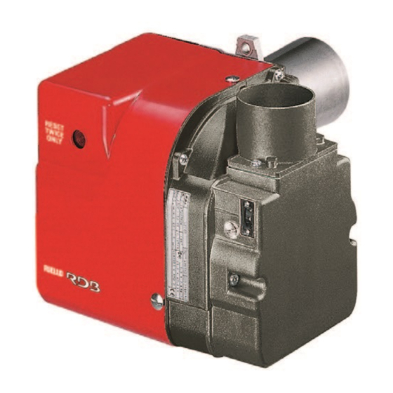
- Page 1 Installation, use and maintenance instructions Light oil burners One stage operation CODE MODEL TYPE 3510225 RDB1 CF 38 501 T3 3510050 RDB1R CF 26 501 T1R 3510150 RDB1R CF 33 501 T2R 3510250 RDB1R CF 38 501 T3R 3510650 RDB2R CF 38 502 T3R...
-
Page 3: Table Of Contents
CONTENTS BURNER DESCRIPTION ... . WORKING ..... . . 1.1 Burner equipment ....4.1 Combustion adjustment. -
Page 4: Technical Data
TECHNICAL DATA 2.1 TECHNICAL DATA TYPE 501T3 501T1R 501T2R 501T3R 502T3R 502T5R – – – – – – Output kg/h Thermal power 23.8 - 37.9 16.6 - 26 21.4 - 33.2 23.8 - 37.9 23.8 - 37.9 33.2 - 46.2 (with air at 20 °C) = 11.86 kWh/kg) Fuel... -
Page 5: Overall Dimensions
2.3 OVERALL DIMENSIONS Flange Burner D4049 D4085 INSTALLATION THE BURNER MUST BE INSTALLED IN CONFORMITY WITH LEGISLATION AND LOCAL STANDARDS. 3.1 BOILER FIXING Put on the flange (1) the screw and two nuts, (see fig. 2). Fix the flange (1) to the boiler door (4) using screws (2) and (if necessary) the nuts (3) interposing the insulating gasket (5), (see fig. -
Page 6: Hydraulic Systems
3.2 HYDRAULIC SYSTEMS Fig. 4 The pump is designed to allow working with two pipes. In order to obtain one pipe working it is necessary to unscrew the return plug (2) (fig. 4), remove the by-pass screw (3) and then screw again the plug (2). -
Page 7: Electrical Wiring
3.3 ELECTRICAL WIRING WARNING DO NOT EXCHANGE NEUTRAL WITH PHASE 50Hz - 230V 50Hz - 230V 501T3 501T1R-2R-3R - 502T3R-5R Main switch Main switch Safety thermostat Safety thermostat Ignition Ignition electrodes electrodes Limit thermostat Limit thermostat CONTROL BOX CONTROL BOX 535RSE/LD 535SE/LD Photoresistance... -
Page 8: Pump
WORKING 4.1 COMBUSTION ADJUSTMENT In conformity with Efficiency Directive 92/42/EEC the application of the burner on the boiler, adjustment and testing must be carried out observing the instruction manual of the boiler, including verification of the CO and CO concentration in the flue gases, their temperatures and the average temperature of the water in the boiler. To suit the required appliance output, fit the proper nozzle, then adjust the pump pressure and the air damper opening in accordance with the following schedule. -
Page 9: Electrodes Setting
4.3 ELECTRODES SETTING IMPORTANT: ATTENTION Fig. 9 THESE DIMENSIONS 4 ± 0.3 mm MUST BE OBSERVED Before removing or assembling the nozzle, loosen the screw (A, fig. 9) and move the electrodes ahead. D5230 2 – 2.5 mm 4.4 PUMP PRESSURE: 12 bar: The pump leaves the factory set at this value. -
Page 10: Maintenance
MAINTENANCE The burner requires periodic maintenance carried out by a qualified and authorised technician in conformity with legislation and local standards. Maintenance is essential for the reliability of the burner, avoiding the excessive consumption of fuel and consequent pollution. Before carrying out any cleaning or control always first switch off the electrical supply to the burner acting on the main switch of the system. -
Page 11: Faults / Solutions
FAULTS / SOLUTIONS Here below you can find some causes and the possible solutions for some problems that could cause a failure to start or a bad working of the burner. A fault usually makes the lock-out lamp light which is situated inside the reset button of the control box (3, fig. - Page 12 RIELLO S.p.A. I-37045 Legnago (VR) Tel.: +39.0442.630111 http:// www.rielloburners.com Subject to modifications...
Need help?
Do you have a question about the RDB1R CF 26 and is the answer not in the manual?
Questions and answers