Table of Contents
Advertisement
Montage und Bedienungsanleitung
Manuel d'entretien
Installation, use and maintenance instructions
Installatie-, gebruiks- en onderhoudsvoorschriften
Oδηγ ε εγκατ σταση , χρ ση και συντ ρηση
Öl-Gebläsebrenner
D
Brûleur fioul
F
Light oil burner
GB
Stookoliebrander
NL
Καυστ ρα Πετρελα ου
GR
Einstufiger Betrieb
Fonctionnement à 1 allure
One stage operation
Eentrapsbranders
Μονοβ θ ιοι
CODE - Κ
ΙΚΟΣ
3739950
MODELL - MODELE
MODEL - ΜΟΝΤΕΛΟ
RG5S
TYP - TYPE
ΤΥΠΟΣ
399 T1
2902623 (2)
Advertisement
Table of Contents

Subscribe to Our Youtube Channel
Related Manuals for Riello Burners RG5S 399T1


Summary of Contents for Riello Burners RG5S 399T1
- Page 1 Montage und Bedienungsanleitung Manuel d’entretien Installation, use and maintenance instructions Installatie-, gebruiks- en onderhoudsvoorschriften Oδηγ ε εγκατ σταση , χρ ση και συντ ρηση Öl-Gebläsebrenner Brûleur fioul Light oil burner Stookoliebrander Καυστ ρα Πετρελα ου Einstufiger Betrieb Fonctionnement à 1 allure One stage operation Eentrapsbranders Μονοβ...
-
Page 2: Table Of Contents
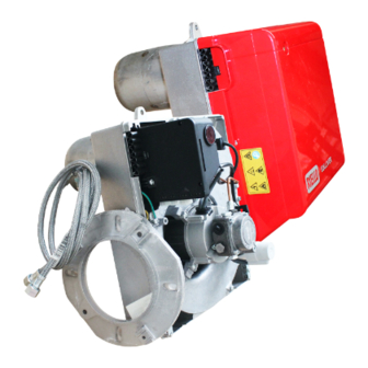
INDEX BURNER DESCRIPTION ... . WORKING ..... . . 1.1 Burner equipment ....4.1 Combustion adjustment. -
Page 3: Technical Data
TECHNICAL DATA 2.1 TECHNICAL DATA TYPE 399 T1 – – Output - Thermal power 13.5 26.1 kg/h 309.5 kW Fuel Light oil, viscosity 4 – 6 mm /s at 20 °C ± Electrical supply Single phase, 50Hz 230 V Motor Run current 2.1 A –... -
Page 4: Installation
INSTALLATION THE BURNER MUST BE INSTALLED IN CONFORMITY WITH LEGISLATION AND LOCAL STANDARDS. 3.1 BOILER FIXING Put on the flange (1) the screw and two nuts, (see fig. 3). Widen, if necessary, the insulating gasket holes (4), (see fig. 4). Fix the flange (1) to the boiler door (3) using screws (5) and (if necessary) the nuts (2) interposing the insulating gasket (4), (see fig. -
Page 5: Hydraulic Systems
3.3 HYDRAULIC SYSTEMS Fig. 7 WARNING: The pump is designed to allow working with two pipes. In order to obtain one pipe working it is necessary to unscrew the pin (2), remove the by-pass screw (3) and then screw again the pin (2), (see fig. -
Page 6: Electrical Wiring
3.4 ELECTRICAL WIRING NOTES: WARNING – Wires of min. 1 mm section. DO NOT EXCHANGE NEUTRAL WITH PHASE (Unless requested otherwise by local standards and legislation). 50Hz 230V – The electrical wiring carried out by the installer must be in compliance with the rules in force in PE L the Country. -
Page 7: Working
WORKING 4.1 COMBUSTION ADJUSTMENT In conformity with Efficiency Directive 92/42/EEC the application of the burner on the boiler, adjustment and testing must be carried out observing the instruction manual of the boiler, including verification of the CO and concentration in the flue gases, their temperatures and the average temperature of the water in the boiler. To suit the required appliance output, choose the proper nozzle and adjust the pump pressure, the setting of the combustion head, and the air damper opening in accordance with the following schedule. -
Page 8: Combustion Head Setting
4.3 COMBUSTION HEAD SETTING, (see fig. 12, page 6) It depends on the output of the burner and is carried out by rotating clockwise or counterclockwise the setting screw (6) until the set-point marked on the regulating rod (7) is level with the outside plane of the nozzle-holder assembly (1). -
Page 9: Burner Start-Up Cycle
HIGH-FLAME SETTING, (see fig. 14, page 7) AIR-DAMPER ADJUSTMENT Loosen the nut (3), turn the screw (1), until the indicator (2) is in the required position. Then, lock the nut (3). PUMP-ADJUSTMENT This is set at 15 bar at the factory. The pressure gauge must be mounted in place of plug (4, fig. -
Page 10: Faults / Solutions
FAULTS / SOLUTIONS Here below you can find some causes and the possible solutions for some problems that could cause a fail- ure to start or a bad working of the burner. A fault usually makes the lock-out lamp light which is situated inside the reset button of the control box (3, fig.
Need help?
Do you have a question about the RG5S 399T1 and is the answer not in the manual?
Questions and answers