
Subscribe to Our Youtube Channel
Related Manuals for Riello Burners RDB1 70-90


Summary of Contents for Riello Burners RDB1 70-90
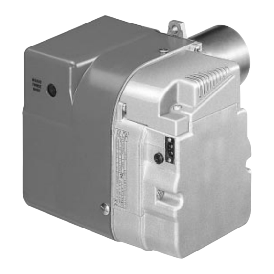
- Page 1 Installation, use and maintenance instructions KEROSENE AND LIGHT OIL BURNER KEROSENE BURNER CODE MODEL TYPE 3748357 RDB1 70 - 90 483T50 3748557 RDB1 50 - 70 485T50 3513007 RDB1 WM 50/70 501T2K 3748757 RDB2 90 - 120 487T50 2902458 (10)
-
Page 3: Table Of Contents
INDEX BURNER DESCRIPTION ... . WORKING ..... . . 1.1 Burner equipment....4.1 Combustion adjustment. -
Page 4: Technical Data
TECHNICAL DATA 2.1 TECHNICAL DATA TYPE 483 T50 485 T50 501T2K 487 T50 kg/h 1.8 – 3.4 1.5 – 2.5 1.8 – 2.8 2.3 – 3.9 Output – Thermal power (with air at 20 °C) 21.6 – 40.6 18 – 29.9 21.6 –... -
Page 5: Installation
INSTALLATION THE BURNER MUST BE INSTALLED IN CONFORMITY WITH LEGISLATION AND LOCAL STANDARDS. 3.1 BOILER FIXING Put on the flange (1) the screw and two nuts, (see fig. 2). Fix the flange (1) to the boiler door (4) using screws (2) and (if necessary) the nuts (3) interposing the insulating gasket (5) , (see fig. - Page 6 The intake-tube / burner system must not allow a loss of over 2 m /h at 0.5 mbar: for instance, the above requirements will be met if you use flues for pressure exhaust of flue gases (the condensation kind). Make sure the air intake tube’s inlet is positioned so that it is not likely to be obstructed by foreign matter and, where necessary, use suitable screens.
-
Page 7: Hydraulic Systems
3.3 HYDRAULIC SYSTEMS WARNING: Fig. 4 Check periodically the flexible pipes conditions. Using kerosene, they have to be replaced at least every 2 years. A metal bowl filter with replaceable micronic filter must be fitted in the oil supply pipe. The pump is designed to allow working with one pipe. -
Page 8: Electrical Wiring
3.4 ELECTRICAL WIRING NOTES: WARNING – Wires of min. 1 mm section. DO NOT EXCHANGE NEUTRAL WITH PHASE (Unless requested otherwise by local stand- ards and legislation). 50Hz - 230V – The electrical wiring carried out by the install- er must be in compliance with the rules in force in the Country. -
Page 9: Working
WORKING 4.1 COMBUSTION ADJUSTMENT In conformity with Efficiency Directive 92/42/EEC the application of the burner on the boiler, adjustment and testing must be carried out observing the instruction manual of the boiler, including verification of the CO and concentration in the flue gases, their temperatures and the average temperature of the water in the boiler. NOZZLES RECOMMENDED : Delavan type W;... -
Page 10: Burner Start-Up Cycle
4.6 BURNER START-UP CYCLE Normal Lock-out due to failure to light Thermostat Motor Ignition transformer Valve Flame Lock-out lamp D5229 Lock out is indicated by a lamp on the control box (3, fig. 1, page 1). MAINTENANCE The burner requires periodic maintenance carried out by a qualified and authorised technician in conformity with legislation and local standards. -
Page 11: Faults / Solutions
FAULTS / SOLUTIONS Here below you can find some causes and the possible solutions for some problems that could cause a failure to start or a bad working of the burner. A fault usually makes the lock-out lamp light which is situated inside the reset button of the control box (3, fig.
Need help?
Do you have a question about the RDB1 70-90 and is the answer not in the manual?
Questions and answers