
Related Manuals for Curtiss-Wright Parvus SWI-22-10-10


Summary of Contents for Curtiss-Wright Parvus SWI-22-10-10
- Page 1 USER MANUAL Saved 10/7/2016 By Judy ® Parvus SWI-22-10 PCI/104-Express 8-/20-Port Gigabit Ethernet Switch MNL-0641-01 Rev A3 ECO-4823 Effective: 04 Oct 16...
- Page 2 Curtiss-Wright reserves the right to change the contents and form of this document, as well as the features and specifications of its products, at any time without notice.
-
Page 3: Table Of Contents
Table of Contents Chapter 1 Introduction ......................9 About This Document ............................ 9 Definitions ............................... 9 Description of Safety Symbols ........................ 9 Functional Description ..........................10 Configurations ............................10 Special Order Options .......................... 10 Features ..............................11 High Port Density ........................... 11 Rugged Design .......................... - Page 4 Parvus SWI-22-10 Curtiss-Wright Loading a New Firmware Image ......................33 Using the Web GUI ............................. 35 Ethernet GUI Features ......................... 35 Web GUI Introduction ........................... 37 Accessing the Web Interface ......................37 Navigation Pane ..........................39 System Buttons ..........................39 Links to Detail Popups ........................
- Page 5 Status Indication ........................... 62 Reliability .............................. 62 Mechanical Specifications ........................... 63 Connector Specifications ..........................63 Environmental Specifications ........................63 Protocol Standards ............................64 Chapter 7 Troubleshooting ....................65 Product Identification ........................... 65 Technical Assistance ..........................65 Returning for Service ..........................65 Chapter 8 Contact Info ......................
- Page 6 Parvus SWI-22-10 Curtiss-Wright Exiting Parvus Debug Mode ....................... 100 Commands Overview ..........................101 OptShow ............................102 OptDefaults ..........................102 EEdump ............................103 Logshow ............................103 optwrapfaultlog ..........................104 LogErase ............................104 Status ............................104 Temp ............................104 Uptime ............................104 version ............................
- Page 7 List of Figures Figure 1. Management Interface Block Diagram SWI-22-10-10 ..............12 Figure 2. Management Interface Block Diagram SWI-22-10-01 ..............13 Figure 3. SWI-22-10-10 Card ........................14 Figure 4. SWI-22-10-01 Card ........................15 Figure 5. SWI-22-10 Card with Thermal Plate ................... 15 Figure 6.
- Page 8 Parvus SWI-22-10 Curtiss-Wright Page 8 of 107 MNL-0641-01 Rev A3 ECO-4823 Effective: 04 Oct 16...
-
Page 9: Chapter 1 Introduction
HAPTER NTRODUCTION The SWI-22-10 is a rugged PCI/104-Express Gigabit Ethernet Switch card equipped with up to twenty triple-speed 10/100/1000Mbps ports for connecting IPv4- and IPv6-compatible computing devices in demanding embedded systems LAN applications. BOUT OCUMENT This manual provides functional and technical descriptions of the SWI-22-10 hardware, instructions on connecting the card to test equipment, operational information on using the SWI-22-10 management consoles and commands, connector descriptions and pinouts, and specifications. -
Page 10: Functional Description
The SWI-22-10 is available with an optional integrated thermal plate, and can be ordered as a standalone card or pre-integrated into the Parvus DuraNET 20-10 switch subsystem. The card can also be integrated by Curtiss-Wright into other rugged enclosures and/or combined with PC/104-based DuraMAR mobile routers or DuraCOR mission computers subsystems. -
Page 11: Features
EATURES High Port Density Up to 20 Gigabit Ethernet Switch ports in single-slot PCI/104-Express form factor (3.6”x3.8”) card; 8-port option also available. Rugged Design -40/+85C extended-temperature operation, vibration-tolerant connectors for cableless/cabled network connections, staked and underfilled components. Carrier Grade ... -
Page 12: Management Interface Overview
Chapter 1 Introduction Parvus SWI-22-10 Curtiss-Wright ANAGEMENT NTERFACE VERVIEW The SWI-22-10 provides two types of console interfaces for switch configuration and management: a serial command line interface (CLI) via RS-232 serial port, and a Web GUI via Ethernet. Each management interface on the card connects to a host PC which acts as the console. -
Page 13: Figure 2. Management Interface Block Diagram Swi-22-10-01
Figure 2. Management Interface Block Diagram SWI-22-10-01 MNL-0641-01 Rev A3 ECO-4823 Effective: 04 Oct 16 Page 13 of 107... -
Page 14: Chapter 2 Hardware Description
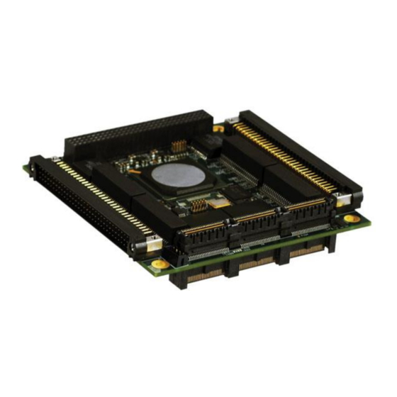
Chapter 2 Hardware Description Parvus SWI-22-10 Curtiss-Wright HAPTER ARDWARE ESCRIPTION This chapter describes the SWI-22-10-XX cards. The major differences in the cards are the number of ports (20 or 8) and whether the thermal plate is factory-installed. SWI-22-10-10, 20 ports ... -
Page 15: Swi-22-10 Thermal Plate
Figure 4. SWI-22-10-01 Card SWI-22-10 T HERMAL LATE The SWI-22-10-01T and -10T include a factory-installed thermal plate for conduction cooling in a no- moving-parts system. Figure 5 shows the SWI-22-10-10T with the factory-installed thermal plate. Figure 5. SWI-22-10 Card with Thermal Plate MNL-0641-01 Rev A3 ECO-4823 Effective: 04 Oct 16... -
Page 16: Eco-4823 Effective: 04 Oct
Chapter 2 Hardware Description Parvus SWI-22-10 Curtiss-Wright Figure 6 shows the mounting holes in the sides of the thermal plate that are used to mount the thermal plate in a chassis for heat dissipation. Figure 6. Thermal Plate Mounting Hole Locations Figure 7 and Figure 8 show where the thermal plate is located relative to the PCB. -
Page 17: Figure 8. Thermal Plate Horizontal Dimensions
The 2D drawings and 3D model for the thermal plate are available to customers that wish to design their own thermal solution. Note: If you do not use the thermal plate available from Curtiss-Wright, then your system design must provide adequate heat dissipation. - Page 18 Chapter 2 Hardware Description Parvus SWI-22-10 Curtiss-Wright Page 18 of 107 MNL-0641-01 Rev A3 ECO-4823 Effective: 04 Oct 16...
-
Page 19: Chapter 3. Hardware Installation
3. H HAPTER ARDWARE NSTALLATION QUIPMENT NSTALLATION To use the SWI-22-10-xx in a lab environment, you must have: Appropriate cables, such as the CBL-SWI-22-10-10 Breakout Cable Set A power source, either: A PCI/104 stack or a PCI/104-Express stack ... -
Page 20: Breakout Cable Set
Chapter 5 for connector pinouts and descriptions. The breakout cable set (CBL-SWI-22-10-10 or CBL-SWI-22-10-01) is available for purchase through Curtiss-Wright and is intended for lab or bench testing purposes only. The SWI-22-10-10 cable set (CBL-SWI-22-10-10, shown in Figure 9) includes the following cables: Cable Qty. -
Page 21: Figure 10. Breakout Cableset (Cbl-Swi-22-10-01)
Cable Qty. Description Function CBL-2551-01 SWI-22-10, external power Connects auxiliary power connector and chassis ground ring lugs to banana plugs for a bench-top power supply. 6’ DB9 M/F serial extension CBL-1536-01 Extends console port connection length if breakout cable is not long enough to reach host computer. -
Page 22: Test Setup Swi-22-10-10
Chapter 3. Hardware Installation Parvus SWI-22-10 Curtiss-Wright SWI-22-10-10 ETUP Figure 11 shows the location of the connectors on the SWI-22-10-10. Figure 11. Connector Locations (SWI-22-10-10) 1. Place the card on an anti-static surface, such as the bag that the card was packaged in, or install it into a PCI/104 or PCI/104-Express stack. -
Page 23: Test Setup Swi-22-10-01
7. Turn on the power supply. 8. After about 18 seconds, a green LED should start flashing on the edge of the board next to the PCI- Express connector. The flashing LED indicates that the card is ready for operation. During this boot process the serial CLI port will output information about the progress of the booting process. -
Page 24: Zeroization
Chapter 3. Hardware Installation Parvus SWI-22-10 Curtiss-Wright 5. Connect one Ethernet port to your host computer or to a network shared by your host computer for access to the Web GUI management interface (GUI). 6. Connect other Ethernet ports to desired equipment for testing. - Page 25 7. end 8. copy running-config startup-config MNL-0641-01 Rev A3 ECO-4823 Effective: 04 Oct 16 Page 25 of 107...
-
Page 26: Chapter 4 Management Interface Description
Chapter 4 Management Interface Parvus SWI-22-10 Curtiss-Wright Description HAPTER ANAGEMENT NTERFACE ESCRIPTION The SWI-22-10 management interfaces provide the network administrator with a set of comprehensive management functions. The network administrator has a choice of two easy-to-use management interfaces: Serial CLI (command line interface) ... -
Page 27: Understanding The Switch Configuration Files
NDERSTANDING THE WITCH ONFIGURATION ILES The switch supports an Industry Standard configuration (ICFG) and stores the configuration in text files in CLI format. The files are either virtual (RAM-based) or stored in flash on the switch. All configuration files except ‘running-config’ are stored in the flash: file system. There are four kinds of configuration files: ... -
Page 28: Using The Cli
Chapter 4 Management Interface Parvus SWI-22-10 Curtiss-Wright Description SING THE This document describes basic usage and configuration of the command line interface (CLI) for the Parvus SWI-22-10. The CLI interface is an industry-standard CLI and consists of configuration commands which provide the ability to configure and view the configuration using the serial console, or Telnet or SSH access. -
Page 29: Set Vlan 1 Ip Address
3. At the Password prompt, press Enter. (There is no default password.) This completes the login sequence. The prompt changes to SWI2210-XXXX#, where XXXX is the serial number of your SWI- 22-10. Username: admin Password: SWI2210-XXXX# At this point the admin user is operating at the highest privilege level, level 15. This means the admin has full control over the switch and its configuration. -
Page 30: Save The Configuration
Chapter 4 Management Interface Parvus SWI-22-10 Curtiss-Wright Description Save the Configuration These steps describe how to perform a basic save operation and view the new configuration file. 1. Copy running-config to startup-config: SWI2210-XXXX# copy running-config startup-config Building configuration... % Saving 1326 bytes to flash:startup-config 2. -
Page 31: Cli Command Groups
CLI C OMMAND ROUPS CLI commands can be grouped into the following functional categories: Manage and show switch settings. Manage configuration and firmware files. Manage system. Manage Parvus extensions. Figure 13 shows the list of Exec commands and the commands available in each group. Appendix A provides more information on the first three command groups, with multiple examples of their use. -
Page 32: Working With Configuration Files
Chapter 4 Management Interface Parvus SWI-22-10 Curtiss-Wright Description ORKING WITH ONFIGURATION ILES Configuration file names are case-sensitive. Saving and Deleting Configuration Files The available operations are copy, dir, more, and delete. copy <source> <destination> Copies source to destination. The source and destination can be one of: ... -
Page 33: Reverting To The Default Configuration
rw 1970-01-01 19:54:01 1237 backup 2 files, 1885 bytes total. ! Use the current running-config for next boot: SWI2210-XXXX# copy running-config startup-config Building configuration... % Saving 1271 bytes to flash:startup-config Reverting to the Default Configuration An explicit ‘copy running-config startup-config’ is necessary to make the change persistent. Rebooting and resetting configuration to defaults is accomplished with the ‘reload’... - Page 34 Chapter 4 Management Interface Parvus SWI-22-10 Curtiss-Wright Description It is possible to swap the active and alternative images, and it is possible to upgrade to a new active image. A swap simply switches the active/alternate designation on each image and reboots the system.
-
Page 35: Using The Web Gui
SING THE The web-based software management method allows the network administrator to configure, manage, view, and control the switches remotely. The Web based Management method also provides help pages for assisting the switch administrator in understanding the usage. SNMP management is standards- based, with configuration parameters specified in the supported MIBs. -
Page 36: Figure 14. Web Gui Top Level Features (Alphabetized)
Chapter 4 Management Interface Parvus SWI-22-10 Curtiss-Wright Description Figure 14. Web GUI Top Level Features (Alphabetized) Page 36 of 107 MNL-0641-01 Rev A3 ECO-4823 Effective: 04 Oct 16... -
Page 37: Web Gui Introduction
GUI I NTRODUCTION This section explains how to access the web GUI, describes page navigation, and explains how to access help. Accessing the Web Interface Once the IP address of the switch is set up, you can use the Web GUI to manage the switch. where the IP address of the switch is . - Page 38 Chapter 4 Management Interface Parvus SWI-22-10 Curtiss-Wright Description 5. The GUI home page is displayed. The standard parts of the GUI are the navigation pane on the left, the large work area, and system buttons in the upper right corner of the window. The default view for the GUI is the monitor for Port States.
-
Page 39: Navigation Pane
Navigation Pane The navigation pane selects what is displayed in the work area. The pane is organized into categories (such as Configuration, Monitor, and Diagnostics) and subcategories (such as System, Green Ethernet, and Ports under Monitor). The categories and subcategories are just navigation tools—they aren't displayed in the work area. - Page 40 Chapter 4 Management Interface Parvus SWI-22-10 Curtiss-Wright Description Note: If you minimize the help window and then try to display help for a new page, the help window may not automatically maximize. Page 40 of 107 MNL-0641-01 Rev A3 ECO-4823...
-
Page 41: Links To Detail Popups
Links to Detail Popups Many of the GUI pages display a table of results, like this example of the system log. Underlined entries in the table (ID 1 and 2) indicate that a detail page is available for the entry. If you click on the underlined item, the display changes to show more information, like this example of detailed system log information for ID 2. -
Page 42: Changing And Saving Configuration Settings
Chapter 4 Management Interface Parvus SWI-22-10 Curtiss-Wright Description HANGING AND AVING ONFIGURATION ETTINGS These instructions walk you through the processes for changing the switch hostname and the admin password, providing tips that are relevant to any configuration change. The instructions then explain how to save the configuration. - Page 43 4. Click the Save button. If you left any optional fields blank, a reminder that the field is empty is displayed. Click OK or return to the page and supply a value. Once all fields have been checked, the change goes into effect immediately. 5.
-
Page 44: Changing The Admin Password (Example)
Chapter 4 Management Interface Parvus SWI-22-10 Curtiss-Wright Description Changing the Admin Password (Example) By default, there is no admin password. To set a password: 1. Use the navigation pane to find and display the appropriate page. The Users Configuration page lists the configured users. You can also use this page to add users. -
Page 45: Saving The Configuration Via The Web Gui
Saving the Configuration via the Web GUI This section explains how to copy running-config to startup-config, thereby ensuring that the currently active configuration will be available at the next reboot. 1. Use the navigation pane to find the appropriate page. Save startup-config is under Maintenance > Configuration. -
Page 46: Managing Configuration Files
Chapter 4 Management Interface Parvus SWI-22-10 Curtiss-Wright Description ANAGING ONFIGURATION ILES Configuration parameters are represented as attribute values. When saving the configuration from the switch, the entire configuration including syntax descriptions is included in the file. The file may then be modified using an editor and loaded to a switch. -
Page 47: Uploading A Configuration File
Uploading a Configuration File You can upload a file from the web browser to any of the files on the switch, except default-config, which is read-only. The upload can replace the current file or create a new file in flash. If the destination is running-config, the file will be applied to the switch configuration. - Page 48 Chapter 4 Management Interface Parvus SWI-22-10 Curtiss-Wright Description 3. Select the destination. The available destination files show the first four files in flash. If the GUI file system is full, the Create a new file option is not available and a message is displayed.
-
Page 49: Activating A Configuration File
5. Click Upload Configuration. A completion message is displayed. Activating a Configuration File Activating a file means initiating the process of completely replacing the existing configuration with that of the selected file. You can activate any of the configuration files present on the switch, except for running- config which represents the currently active configuration. -
Page 50: Chapter 5 Connector Descriptions
Chapter 5 Connector Descriptions Parvus SWI-22-10 Curtiss-Wright HAPTER ONNECTOR ESCRIPTIONS This chapter identifies connector part numbers, locations, and pinouts to facilitate fabrication of cables that can connect to the SWI-22-10. The chapter describes the card-specific connectors for the SWI-22- 10-10 and SWI-22-10-01 and then describes the connectors common to both cards. Finally, implementation information for the console, zeroize, and LED ports is provided. -
Page 51: J2 Pinout
Figure 16 shows the physical orientation for J2 and J3. Figure 16. SWI-22-10-10 Ethernet Connector Detail J2 Pinout J2 PIN SIGNAL J2 PIN SIGNAL J2 PIN SIGNAL GBE16_A_P GBE12_A_P GBE12_B_P GBE16_A_N GBE12_A_N GBE12_B_N GBE16_B_P GBE12_C_P GBE12_D_P GBE16_B_N GBE12_C_N GBE12_D_N CHASSIS GBE11_A_P GBE11_B_P GBE16_C_P... -
Page 52: J3 Pinout
Chapter 5 Connector Descriptions Parvus SWI-22-10 Curtiss-Wright J3 Pinout J3 PIN SIGNAL J3 PIN SIGNAL J3 PIN SIGNAL GBE20_A_P GBE6_A_P GBE6_B_P GBE20_A_N GBE6_A_N GBE6_B_N GBE20_B_P GBE6_C_P GBE6_D_P GBE20_B_N GBE6_C_N GBE6_D_N CHASSIS GBE5_A_P GBE5_B_P GBE20_C_P GBE5_A_N GBE5_B_N GBE20_C_N GBE5_C_P GBE5_D_P GBE20_D_P... -
Page 53: Swi-22-10-01 Card-Specific Connectors
SWI-22-10-01 C PECIFIC ONNECTORS UMBERS The following table shows the manufacturer part numbers for the SWI-22-10-01 connectors (identified in Figure 17), together with the suggested mating connectors. Connector Part Number Mating Connector P4, P7 Molex 87833-2420 Molex 51110-2451, use with Molex crimp pins 50394-8052 or -8200 P5, P6 Molex 87833-1620 Molex 51110-1651, use with Molex crimp pins 50394-8052 or -8200... -
Page 54: P4 Pinout
Chapter 5 Connector Descriptions Parvus SWI-22-10 Curtiss-Wright Figure 18. SWI-22-10-01 Ethernet Connector Detail Connectors P4 and P7 pin arrangement Connectors P5 and P6 pin arrangement P4 Pinout P7 Pinout P10 PIN SIGNAL P10 PIN SIGNAL P13 PIN SIGNAL P13 PIN... -
Page 55: Connectors Common To All Swi-22-10 Models
SWI-22-10 M ONNECTORS OMMON TO ODELS OMMON ONNECTOR OCATIONS Figure 19 shows the location of the common connectors for all versions of the SWI-22-10. These connectors are: Auxiliary power connector (P3) Mounting holes (MTG1, MTG2) PCI Connectors (J1 & J6) ... -
Page 56: Mounting Holes (Mtg1, Mtg2)
Chapter 5 Connector Descriptions Parvus SWI-22-10 Curtiss-Wright Figure 20. Auxiliary Power Connector Pin Orientation (P3) P3 Pin Signal Description +3.0-5.5VDC Input (measured at P3) +3.0-5.5VDC Input (measured at P3) +V Return +V Return (MTG1, MTG2) OUNTING OLES Figure 19 shows the location of the card mounting holes. MTG1 and MTG2 must be connected to system chassis ground via a 4-40 screw and star washer. -
Page 57: Pci-Express Connectors (J5 & J8)
PCI-E (J5 & J8) XPRESS ONNECTORS See www.pc104.org for standardization details. PCIe Bus Pin Matrix (PCI/104 Express Standard) (J5 & J8) MNL-0641-01 Rev A3 ECO-4823 Effective: 04 Oct 16 Page 57 of 107... -
Page 58: Console Port
Chapter 5 Connector Descriptions Parvus SWI-22-10 Curtiss-Wright ONSOLE On the SWI-22-10-10-10, the console port is located on a set of pins on J3. Signal Function CONSOLE_RXD Receive signal to the switch CONSOLE_TXD Transmit signal from the switch CONSOLE_GND Console signal ground On the SWI-22-10-10-01, the console port is located on a set of pins on P4. -
Page 59: Figure 22. Recommended Swi-22-10-10 Led Port Interface Circuit
LED_ nRESET LED_CLOCK LED_PWR LED_DO LED_GND These pins implement a serial interface that outputs a string of LED on/off bits that indicate the status of the Ethernet ports and the overall status of the switch. The schematic in Figure 22 shows the recommended circuit that the standard firmware can drive to support two LEDs for each of the 20 copper Ethernet ports on the SWI-22-10-10. - Page 60 Chapter 5 Connector Descriptions Parvus SWI-22-10 Curtiss-Wright LED Behavior A port LED, when there is no link on its associated port, will not be illuminated. A port LED, when there is a 1000Mb link on its associated port, will be illuminated steady green.
-
Page 61: Chapter 6 Specifications
HAPTER PECIFICATIONS ENERAL PECIFICATIONS PPLICATIONS Small form factor embedded systems, including standalone or stacking architectures (i.e., PC/104-Plus, PCI-104, PCIe/104, PCI/104-Express, EBX, EPIC) High-speed Gigabit Ethernet Local Area Network (LAN) switching for IP-enabled equipment, such as onboard computers, cameras, sensors, monitoring devices, and command-and-control gear in harsh temperature and vibration environments ... -
Page 62: Port Features
Chapter 6 Specifications Parvus SWI-22-10 Curtiss-Wright EATURES 20-Port: 20x Copper Gigabit Ethernet 1000BaseT, RS-232 Console, Harwin connectors 8-Port: 8x Copper Gigabit Ethernet 1000BaseT, RS-232 Console, Molex connectors AYER WITCHING Port Control: port-speed, duplex mode, flow control, port frame size (jumbo frames), port state, port status (link monitoring), port statistics (MIB counters) ... -
Page 63: Mechanical Specifications
ECHANICAL PECIFICATIONS Form Factor: PCI/104-Express form factor compliant (PCIe, PCI buses) Card only: 3.6” x 3.8” (90 x 96 mm) L x W (excluding Ethernet connector extensions) Card with Thermal Plate: 3.86” x 4.11” x 0.63” (98 x 104.5 x 16mm) L x W x H (excluding Ethernet and bottom-side bus connector extensions) ... -
Page 64: Protocol Standards
Chapter 6 Specifications Parvus SWI-22-10 Curtiss-Wright ROTOCOL TANDARDS IEEE 802.3 10Mbps 10BASE-T (Ethernet) IEEE 802.3u 100BASE-TX 100Mbps (Fast Ethernet) IEEE 802.3ab 1000BASE-T 1000Mbps (Gigabit Ethernet) IEEE 802.3ad Link Aggregation IEEE 802.3af PoE Support IEEE 802.3az Energy Efficient Ethernet ... -
Page 65: Chapter 7 Troubleshooting
HAPTER ROUBLESHOOTING RODUCT DENTIFICATION The product is labeled with the Curtiss-Wright P/N and serial number. Please refer to this information when communicating with Technical Support. ECHNICAL SSISTANCE If you have a technical question or if you cannot isolate a problem with your product, please call or e-mail... -
Page 66: Chapter 8 Contact Info
Chapter 8 Contact Info Parvus SWI-22-10 Curtiss-Wright HAPTER ONTACT Company contact info: Defense Solutions Division Curtiss-Wright 3222 S. Washington St. Salt Lake City, Utah, USA 84115 (801) 483-1533 FAX (801) 483-1523 Web-site: www.cwcdefense.com Sales: +1(800) 483-3152 or (801) 483-1533 slp_sales@curtisswright.com... -
Page 67: Appendixa Cli Reference
A CLI R PPENDIX EFERENCE This appendix describes basic usage and configuration of the command line interface (CLI) for the Parvus SWI-22-10. The CLI interface is an industry-standard CLI and consists of configuration commands which provide the ability to configure and view the configuration using the serial console, or Telnet or SSH access. Even if there is no network connectivity, you can still manage the switch using a serial connection. -
Page 68: How The Cli Works
Appendix A CLI Reference Parvus SWI-22-10 Curtiss-Wright CLI W OW THE ORKS The CLI has several different modes, and some commands are restricted to a specific mode. The top-level mode is called exec mode. It allows the user to perform operations related to configuration files, reloading defaults, displaying system information, etc., but it does not allow the... -
Page 69: Accessing The Cli Help Menu
CLI H CCESSING THE To view the top-level help, type help or ? at the system prompt. If you use the ?, the help is displayed as soon as you type the ?—you don't need to press Enter. SWI2210-XXXX# help Help may be requested at any point in a command by entering a question mark '?'. - Page 70 Appendix A CLI Reference Parvus SWI-22-10 Curtiss-Wright This example 1 shows the results for each help key. Comment lines have been added to the example to clarify what is shown; the comments are in italics and begin with an exclamation point (!).
-
Page 71: Using The Keyboard
SING THE EYBOARD The CLI provides a rich set of keys to assist the user while working with the command line. The functionality is divided into: Basic line editing Command history Context-sensitive help Long lines and pagination The table summarizes the keys supported by the CLI. -
Page 72: Command History
Appendix A CLI Reference Parvus SWI-22-10 Curtiss-Wright OMMAND ISTORY A session maintains a non-persistent command history of previously entered command lines. The history can be up to 32 lines long. Once full, a new line will push the oldest entry out. -
Page 73: Controlling The Display
ONTROLLING THE ISPLAY The session configuration controls the width of the terminal in characters and the height in lines. It uses these parameters to control handling of long input lines and to control pagination of multi-line output. For details about changing these parameters, please refer to section XX. Long Lines Long lines come into play when a line is longer than the terminal width minus the prompt. -
Page 74: Understanding Commands
Appendix A CLI Reference Parvus SWI-22-10 Curtiss-Wright NDERSTANDING OMMANDS Command Structure A command is a single line of text consisting of keywords and parameters, for example: SWI2210-XXXX# show vlan id 10 SWI2210-XXXX# show vlan id 20 The keywords are show, vlan, and id. 10 and 20 are parameters that could contain a different value in another command invocation. -
Page 75: Additional Syntax Elements
show erps [ <groups> ] [ detail | statistics ] The show erps command is a bit more complex: ‘show’ and ‘erps’ are mandatory, but the remaining parameters and keywords are optional. You can enter group IDs and optionally specify either ‘statistics’ or ‘detail’. -
Page 76: Ethernet Interface Naming
Appendix A CLI Reference Parvus SWI-22-10 Curtiss-Wright THERNET NTERFACE AMING An Ethernet interface (“port”) is identified by three pieces of information: Its type: FastEthernet, GigabitEthernet, 2.5GigabitEthernet, 5GigabitEthernet, 10GigabitEthernet. The switch it belongs to. For non-stacking systems this value is always 1. -
Page 77: Filtering Output
ILTERING UTPUT The output from commands can in most cases be filtered to limit the output to only those lines that match/trigger a specific string. The available filtering is: Begin – display the first line that begins with the matching string and all subsequent lines ... -
Page 78: Using 'No' Forms To Reset Or Remove Configuration Values
Appendix A CLI Reference Parvus SWI-22-10 Curtiss-Wright ‘ ’ F SING ORMS TO ESET OR EMOVE ONFIGURATION ALUES Almost all configuration commands have a “no” form to negate or set its default. In general, the no form is used to reverse the action of a command or reset a value back to the default. For example, the ‘no ip routing’... - Page 79 EXEC Commands The EXEC commands include the following: SWI2210-XXXX# ? clear Reset functions configure Enter configuration mode copy Copy from source to destination debug Debugging functions delete Delete one file in flash: file system Directory of all files in flash: file system disable Turn off privileged commands To run exec commands in config mode...
- Page 80 Appendix A CLI Reference Parvus SWI-22-10 Curtiss-Wright thermal-protect Display thermal protection status. upnp Display UPnP configurations users Display information about terminal lines version System hardware and software status vlan VLAN status voice Voice appliance attributes SWI2210-XXXX# Configuration Commands Configuration commands allow you to configure features and available options of the device. This is the list for Global Configuration Mode.
-
Page 81: Modes
startup-config Startup configuration SWI2210-XXXX# copy Clear Commands Clear commands clear (reset) specified settings to factory defaults. SWI2210-XXXX# clear ? access Access management access-list Access list dot1x IEEE Standard for port-based Network Access Control Ethernet Protection Switching. erps Ethernet Ring Protection Switching Ethernet Virtual Connections Interface Internet Protocol config commands ipv6... - Page 82 Appendix A CLI Reference Parvus SWI-22-10 Curtiss-Wright pvlan Private VLAN Quality of Service rmon Configure Remote Monitoring on an interface sflow Statistics flow. shutdown Shutdown of the interface. snmp-server Set SNMP server's configurations spanning-tree Spanning Tree protocol speed Configures interface speed. If you use 10, 100, or 1000 keywords with the auto keyword the port will only advertise the specified speeds.
-
Page 83: Frequently Used Cli Commands
CLI C REQUENTLY OMMANDS This section demonstrates how to use common CLI commands together to perform these tasks: Reset the configuration to factory defaults. Set the device hostname. View the current IP configuration. Set the switch IP address. ... -
Page 84: Set The Switch Ip Address
Appendix A CLI Reference Parvus SWI-22-10 Curtiss-Wright Set the Switch IP Address To display the current IP address settings, enter the following commands: # show ip interface brief Vlan Address Method Status ---- -------------------- -------- ------ 192.0.2.1/22 Manual To set up the switch with a static IP address, enter the following commands. This example sets the switch IP address to 192.0.2.1 with a subnet mask of 255.255.252.0:... -
Page 85: Using 'Show' Commands
‘ ’ C SING SHOW OMMANDS The family of ‘show’ commands is the cornerstone of CLI-based system monitoring. Most features implement one or more ‘show’ commands that will display a relevant mix of status and configuration. Please note: The exact set of available commands, parameters and output format depends on the system configuration and software version, so some of the following commands and examples may not be applicable to all systems. -
Page 86: Showing Command Help
Appendix A CLI Reference Parvus SWI-22-10 Curtiss-Wright voice Voice appliance attributes Showing Command Help Example: Using Context-sensitive Help for Discovery The context-sensitive help feature for syntax display is useful as well while drilling down on the exact command to execute. In the following example the user discovers the proper command ‘show ip statistics system’... -
Page 87: Show Running-Config
Show Running-Config ‘running-config’ consists of a list of commands that, taken together, result in the currently running system configuration. This list of commands is usually not 100% identical to the list of commands a user has input to configure the device. That is because ‘running-config’ is a textual representation of the system configuration which is stored in binary form in the RAM memory of the device. - Page 88 Appendix A CLI Reference Parvus SWI-22-10 Curtiss-Wright show running-config feature <feature_name> [ all-defaults ] Only output the commands relevant to a particular feature. The feature list depends on system configuration and software version. For example: SWI2210-XXXX# show running-config feature ?
-
Page 89: Configuring The System
show running-config interface vlan <list> [ all-defaults ] Show running-config for the specific list of VLAN interfaces, for example: SWI2210-XXXX# show running-config interface vlan 1-10 Building configuration... interface vlan 1 ip address dhcp fallback 172.16.1.2 255.255.0.0 In this example there is only one VLAN interface on the system. show running-config line { console | vty } <list>... - Page 90 Appendix A CLI Reference Parvus SWI-22-10 Curtiss-Wright Step 5: Inspect and verify the configuration (some output omitted for brevity): SWI2210-XXXX# show running-config Building configuration... hostname SWI2210-XXXX username admin privilege 15 password encrypted Zm9v vlan 1 name default interface GigabitEthernet 1/1...
-
Page 91: Advanced Concepts
DVANCED ONCEPTS NDERSTANDING ODES AND MODES The CLI implements a number of modes that control the available command set. The modes are further influenced by the privilege level of the user; some modes or commands are only accessible to administrators while others require no privileges beyond log in. There are three major modes, Exec, Privileged Exec and Config. - Page 92 Appendix A CLI Reference Parvus SWI-22-10 Curtiss-Wright It is possible for a user to transition between these modes using certain commands, subject to the user’s privilege level and the current session privilege level (see section XXX). The initial mode is determined by the privilege level of the user logging in. If the privilege level is 0 or 1, the user is unprivileged and begins in the (Unprivileged) Exec mode.
-
Page 93: Cli Mode Transitions
CLI Mode Transitions Figure 24 illustrates the possible transitions between major modes and sub-modes, and some of the relevant commands. Figure 24. CLI Mode Transition Commands Example: Changing Between CLI Modes ! Initial mode for this example is Unprivileged Exec. Raise level ! (and change mode): SWI2210-XXXX>... -
Page 94: Understanding Privilege Levels
Appendix A CLI Reference Parvus SWI-22-10 Curtiss-Wright NDERSTANDING RIVILEGE EVELS A privilege level is a number in the range 0 to 15, inclusive, with 0 being the lowest. It is assigned to a user session and used to determine access to CLI commands: Only commands at the same or lower privilege level can be accessed. -
Page 95: Managing Users
ANAGING SERS This section describes local user management on the device. RADIUS and TACACS+ user management is beyond the scope of this document. It is possible to create several user accounts on a system. Each user account has a set of configurable attributes: ... -
Page 96: Understanding Terminal Parameters
Appendix A CLI Reference Parvus SWI-22-10 Curtiss-Wright NDERSTANDING ERMINAL ARAMETERS Each login to the system--whether via the serial console or telnet or ssh-- creates a session. The session is initialized with settings that are configurable from the ‘line’ configuration sub-mode, but most of them can also be changed from exec mode while the session is active. - Page 97 Example: Changing Terminal Parameters This example shows how to change some values for the current session and for all future console sessions. ! First inspect current settings for this session: SWI2210-XXXX# show terminal Line is con 0. * You are at this line now. Alive from Console.
-
Page 98: Using Banners
Appendix A CLI Reference Parvus SWI-22-10 Curtiss-Wright SING ANNERS The system provides three different banners--text that is output as messages to the user: The Message Of The Day banner (MOTD), displayed upon connection to the system, or when a console login attempt has timed out ... -
Page 99: Appendix B Parvus Cli Enhancements
CLI E PPENDIX ARVUS NHANCEMENTS This appendix describes the Parvus enhancements to the SWI-22-10 CLI software. The enhancements provide additional commands for viewing system data, running manufacturing tests, and setting options for advanced functions such as data zeroization. These functions are available only through the CLI; they do not have GUI equivalents. -
Page 100: Exiting Parvus Debug Mode
Appendix B Parvus CLI Enhancements Parvus SWI-22-10 Curtiss-Wright XITING ARVUS EBUG To exit debug mode, you need to return to the root level and then reboot the switch. You can use either the up command or a /. 1. Type 'up' to move up one level or '/' to go to root level. -
Page 101: Commands Overview
OMMANDS VERVIEW Commands are persistent, meaning values are changed immediately and written to permanent storage. Commands are not case-sensitive. They are displayed with capitals for readability. Commands cannot be abbreviated. As shown in the summary table, some commands are for manufacturing use only (e.g., Built-in Test);... -
Page 102: Optshow
Appendix B Parvus CLI Enhancements Parvus SWI-22-10 Curtiss-Wright OptShow Displays the current values of all Parvus persistent options. Syntax Debug Parvus OptShow Example SWI2210-XXXX:/Debug/Parvus>optshow Parvus options: Fault log wrapping: enabled Watchdog enabled: enabled Zeroize enabled: disabled Zeroize polarity: +12 VDC Zeroize style: 0 - Clear configuration. -
Page 103: Eedump
EEdump Display contents of eeprom. Syntax Debug Parvus EeDump <addr> <item_cnt> <addr> is the starting address <item_cnt> is the number of locations to display. Default: 1 Example SWI2210-XXXX:/Debug/Parvus>eedump 0 348 Dumping EEPROM. 348 bytes @ 0x0000... 00000 00 04 39 4E 00 04 3A 4D-00 04 37 40 00 04 38 4F ..9N..:M..7@..8O 00010 01 10 00 14 58 02 64 64-64 64 73 73 73 73 CA 00... -
Page 104: Optwrapfaultlog
Appendix B Parvus CLI Enhancements Parvus SWI-22-10 Curtiss-Wright optwrapfaultlog Enables or disables fault log wrapping. If wrapping is enabled and the fault log is full, the fault log wraps and overwrites older entries. Otherwise it stops accepting new entries. Syntax Debug Parvus OptWrapFaultLog <integer>... -
Page 105: Version
Syntax uptime Example SWI2210-XXXX:/Debug/Parvus>uptime Up time 0:01:38:42 (days:hh:mm:ss) Lifetime 4:12:32:42 SWI2210-XXXX:/Debug/Parvus> version Show Parvus version number. Syntax version Example SWI2210-XXXX:/Debug/Parvus>version Parvus version 1.0.0. SWI2210-XXXX:/Debug/Parvus> xoshow Show registers from Silicon Labs Si570 Programmable XO. Syntax Debug Parvus XoShow Example SWI2210-XXXX:/Debug/Parvus>xoshow Si570 HS_DIV = 1, N1 = 7, RFREQ = 0x2BC0CA731 (11744880433). SWI2210-XXXX:/Debug/Parvus>... -
Page 106: Zeroize
Appendix B Parvus CLI Enhancements Parvus SWI-22-10 Curtiss-Wright EROIZE For security, the board provides a digitial zeroize input. This section describes the available zeroization parameters. For more information on the signal, refer to "Zeroization" in Chapter 3. optzdelay Sets the debounce time (the minimum amount of time the zeroize input must be asserted before the zeroize feature is invoked). - Page 107 MNL-0641-01 Rev A3 ECO-4823 Effective: 04 Oct 16 Page 107 of 107...
Need help?
Do you have a question about the Parvus SWI-22-10-10 and is the answer not in the manual?
Questions and answers