
Subscribe to Our Youtube Channel
Related Manuals for Curtiss-Wright DuraNET 1059


Summary of Contents for Curtiss-Wright DuraNET 1059
- Page 1 USER MANUAL DuraNET 1059 Rugged 5-Port 10/100 Ethernet Switch PRV-1308-xx MNL-0571-01 Rev A3 ECO-4895 Effective: 22 Jan 16...
- Page 2 Curtiss-Wright reserves the right to change the contents and form of this document, as well as the features and specifications of its products, at any time without notice.
-
Page 3: Table Of Contents
Block Diagram ............................... 5 Features ............................... 6 Chapter 2 Quick Start-up ......................8 Installation ..............................8 Connecting to the DuraNET 1059 ......................... 8 Power-up ............................... 9 Starter Cable Set ............................10 Chapter 3 Connector Descriptions ..................11 Connector Identification ..........................11 Connector Part Numbers .......................... - Page 4 DuraNET 1059 User Manual Software Guide ............................25 Com Port ............................... 25 Setting the Egress Ports ........................26 Operation of VLAN GUI Window ......................27 Menu Operation ............................ 28 Glossary ..........................29 Page 4 of 31 MNL-0571-01 Rev A3 ECO-48954895...
-
Page 5: Chapter 1 Introduction
This section provides a functional description of the DuraNET 1059. Functional Description The DuraNET 1059 is a rugged unmanaged Ethernet switch node designed to provide local area network (LAN) connectivity to IP-enabled computers and other net-centric devices. Weighing in at less than 2 lbs... -
Page 6: Features
Chapter 1 Introduction DuraNET 1059 User Manual Features Ports Five Auto-Detecting 10/100BaseT Ethernet Auto-Negotiation Between 10BaseT & • • Ports 100BaseT Auto-MDI/MDIX Crossover Auto-Sensing of Full or Half Duplex on • • 100BaseTX/10BaseT Each Port Any Port Can Serve as Uplink for Network •... - Page 7 DuraNET 1059 User Manual Chapter 1 Introduction Civil and Military In-Vehicle Networking Layer 2 Switching in Local Area Network (LAN) • • 24/28V Vehicle/Aircraft Installations Situational Awareness / Net-Centric • • Operations Unmanaged Switch Port Expansion for a • DuraMAR Router Options CBL-1537-01 - Starter Cable Set with Mating MIL-C-38999 Connectors to RJ-45 &...
-
Page 8: Chapter 2 Quick Start-Up
Chapter 2 Quick Start-up DuraNET 1059 User Manual Chapter 2 Quick Start-up This section describes the installation of the DuraNET 1059. It then describes the power-up of the assembly. The DuraNET 1059 is factory configured to provide five auto detecting IEEE 802.3/u complaint (10/100mpbs) Ethernet ports. -
Page 9: Power-Up
DuraNET 1059 User Manual Chapter 2 Quick Start-up When you connect your network devices, make sure you don’t exceed the maximum cabling distances, which are listed in the following table: Table 2.1 Maximum Cabling Distances From Maximum Distance Switch Switch or Hub... -
Page 10: Starter Cable Set
DuraNET 1059 User Manual Each of the ports can be tested through the use of a simple ping test between two Ethernet capable devices connected to the DuraNET 1059 to ensure connectivity. Starter Cable Set The following cable set is available for purchase through the sales department and is meant to be for lab or bench testing purposes only. -
Page 11: Chapter 3 Connector Descriptions
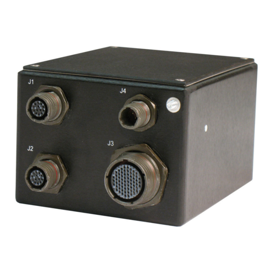
DuraNET 1059 User Manual Chapter 3 Connector Descriptions Chapter 3 Connector Descriptions This chapter includes the pinouts and signal descriptions for the DuraNET 1059. Also provided in this section are connector part numbers along with suggested mating connectors. Connector Identification Table 3.1 Connectors... -
Page 12: Connector Part Numbers
This section provides the pinouts necessary for creating cables that would properly connect to this assembly. Note: If custom cabling is not designed and built by Curtiss-Wright, all EMI and EMC design considerations for the cabling harness must be handled by the party responsible for building said cabling. -
Page 13: J2 Switched Ethernet Port 1
DuraNET 1059 User Manual Chapter 3 Connector Descriptions Connector J1 pins 5 through 13 are not connected. J2 Switched Ethernet Port 1 Connector Alignment: facing insert side of connector, master keyway is facing up. Table 3.4 J2 Pin Signals Signal... -
Page 14: J4 Dc Power
Chapter 3 Connector Descriptions DuraNET 1059 User Manual Rx2+ Receive Positive Tx4- Transmit Negative Rx2- Receive Negative 19 -22 Not Connected Tx3+ Transmit Positive Rx4+ Receive Positive Tx3- Transmit Negative Rx4- Receive Negative Connector J3 pins 25 through 66 are not connected. -
Page 15: Chapter 4 Specifications
• Isolation: Galvanically Isolated Power Supply • Environmental Specifications This section describes the environmental standards that the DuraNET 1059 has either been designed to meet or tested to. Temperature Designed to meet MIL-STD-810F Operating: -40ºC to +85ºC (-40ºF to +185ºF) •... -
Page 16: Shock / Vibration
• Random Vibration: 0.022-G²/10-Hz to 0.0026-G²/2000-Hz • Reliability (MTBF) The following table shows the predicted values for reliability of the DuraNET 1059 as a Mean Time Between Failures (MTBF) and failures per million hours (fpmh): Failure Rate Test Standard (Failures Per Million Hours) MTBF (Hours) MIL-HDBK-217F (@25°C Ground Benign) - Page 17 DuraNET 1059 User Manual Chapter 4 Specifications Figure 4.1 Front and Rear Dimensions Figure 4.2 Side Dimensions Figure 4.3 Mounting Dimensions (Bottom Side) MNL-0571-01 Rev A3 ECO-48954895 Effective: 22 Jan 16 Page 17 of 31...
-
Page 18: Mounting Instructions
• Important: Ensure that a mounting screw length is chosen such that no more than 0.5” protrudes inside of the DuraNET 1059. If a longer screw is used, damage may occur to the internal components. Page 18 of 31 MNL-0571-01 Rev A3... -
Page 19: Chapter 5 Troubleshooting
This product identification marking is also valid. If your Ethernet switch is marked as shown here, please refer to the unit as a DuraNET 1059 when communicating with the support team. Figure 5.3 Model and Serial Number Identification MNL-0571-01 Rev A3... -
Page 20: Faq
Particularly other Marvell based chipsets. If this is the case, please ensure to test other Ethernet capable devices with the DuraNET 1059 to verify that it is working. Also, the auto-polarity and auto-crossover capabilities of the unit can sometimes in rare instances have incompatibilities with other such plug-and-play devices and chipsets. -
Page 21: Technical Assistance
Maintenance The DuraNET 1059 is a rugged Ethernet switch designed for harsh mobile environments, such as railway and military applications. As such, it requires no maintenance except light cleaning for aesthetic appeal, isopropyl alcohol works best. If anything beyond this needs to be done refer to the “Returning for Service”... -
Page 22: Chapter 6 Contact Info
Chapter 6 Contact Info DuraNET 1059 User Manual Chapter 6 Contact Info Company contact info: Defense Solutions Division Curtiss-Wright 3222 S. Washington St. Salt Lake City, Utah, USA 84115 (801) 483-1533 FAX (801) 483-1523 Website: www.curtisswrightds.com/parvus Sales: +1(800) 483-3152 or (801) 483-1533 slp_sales@curtisswright.com... -
Page 23: Appendix A Vlan Operation
DuraNET 1059 User Manual Appendix A VLAN Operation Appendix A VLAN Operation Port-Based VLAN PRV-1308-03 supports field programmable, port-based VLAN functionality. Port-based VLANs are a type of VLAN where packet forwarding decisions are based on the MAC address of the destination and its associated port. -
Page 24: Vlan Software Quick Start Setup Guide
0, 3, and 4 can only talk to port 1 and port 2 is not allowed to send data to any ports. VLAN Software Quick Start Setup Guide In order to change the VLAN configuration on the DuraNET 1059, Curtis-Wright has provided the user with a simple-to-use GUI program. Implementation of the program is through an RS-232 serial cable connection between a COM port on the host computer and the serial port on the switch. -
Page 25: Software Guide
DuraNET 1059 User Manual Appendix A VLAN Operation Software Guide This section describes how to use the VLAN GUI program to set up VLAN configurations on the DuraNET-1059. A screen shot of the program is shown below. Figure 4) VLAN GUI Window... -
Page 26: Setting The Egress Ports
Appendix A VLAN Operation DuraNET 1059 User Manual Setting the Egress Ports Since port-based VLANs only govern outgoing traffic, it necessary to define the egress for all ports. An egress port is defined as the port to which data packets are sent. A visual example is provided below. -
Page 27: Operation Of Vlan Gui Window
DuraNET 1059 User Manual Appendix A VLAN Operation Operation of VLAN GUI Window Figure 6) Manipulations of VLAN GUI Window In the above figure, The GUI is divided into four areas: a) Text display window area for “Sent Command to Switch” and “Received Reply from Switch”... -
Page 28: Menu Operation
VLAN configuration schemes. Note this does not affect the current VLAN settings of the switch. SET– This button is used for internal troubleshooting or testing by Curtiss-Wright. Typing a command in the text box on the top right of the GUI window, and then pressing this button will set the switch’s registers. -
Page 29: Glossary
DuraNET 1059 User Manual Glossary Glossary 10BaseT 10 Mbps Ethernet system based on Manchester signal encoding transmitted over Category 3 or better twisted-pair cable. 100BaseTX 100-Mbps Fast Ethernet specification using Category 5 UTP wiring. Based on the IEEE 802.3u standard. - Page 30 Glossary DuraNET 1059 User Manual router A device that connects two or more LANs at the network layer of the OSI model. Like bridges, routers operate in store-and-forward mode, buffering each packet into memory before determining the destination of the frame. A router also amends the header on each frame once it buffered the frame into memory, to reflect the routing decision that was made.
- Page 31 DuraNET 1059 User Manual Glossary {Parvus back cover, 8.5 x 11 picture inserted in front of text. DO NOT DELETE THE COMMENTS OR THIS PAGE. These comments are only visible in Normal view. The picture hides these comments when you print the manual or view it in Print Layout or Print Preview.}...
Need help?
Do you have a question about the DuraNET 1059 and is the answer not in the manual?
Questions and answers