Panasonic WX-CC411 Operating Instructions Manual
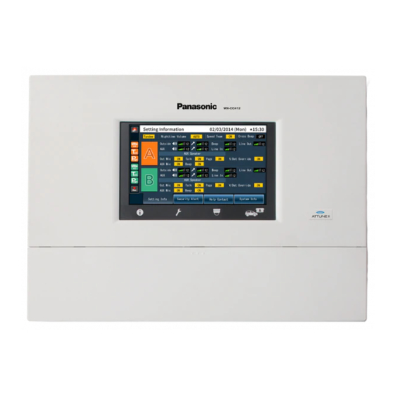
Center module
Hide thumbs
Also See for WX-CC411:
- Operating instructions manual (37 pages) ,
- Operating instructions manual (84 pages)
Advertisement
Advertisement
Table of Contents

Related Manuals for Panasonic WX-CC411


Summary of Contents for Panasonic WX-CC411
- Page 1 Center Module Operating Instructions WX-CC411 Model No. WX-CC412...
- Page 2 ENGLISH VERSION FEDERAL COMMUNICATIONS COMMISSION INTERFERENCE STATEMENT This equipment has been tested and found to comply with the limits for a Class A digital device, pursuant to part 15 of the FCC Rules. These limits are designed to provide reasonable protection against harmful interference when the equipment is operated in a commercial environment.
- Page 3 For U.S.A. WARNING: This product contains a CR Coin Cell Lithium Battery • This apparatus must be earthed. which contains Perchlorate Material – special handling • Apparatus shall be connected to a main socket outlet may apply.See with a protective earthing connection. www.dtsc.ca/gov/hazardouswaste/perchlorate/ •...
-
Page 4: Important Safety Instructions
Important Safety Instructions 1) Read these instructions. 2) Keep these instructions. 3) Heed all warnings. 4) Follow all instructions. 5) Do not use this apparatus near water. 6) Clean only with dry cloth. 7) Do not install near any heat sources such as radiators, heat registers, stoves, or other apparatus (including amplifiers) that produce heat. -
Page 5: Product Outline
- Built-in scheduler can replace greeter messages at a specified time, and it can also play reminder messages automatically. - Panasonic IP cameras can be registered up to 4 units, and their videos can be checked with the LCD of center module. - Page 6 Precautions Handle this product with care. The product contains sensitive components that can be damaged by improper handling or storage. Repair or replace any defective components. Use this product for indoor use only. Do not expose this product to direct sunlight for hours and do not install the product near a heater or an air conditioner.
- Page 7 Name and descriptions of each parts and basic screen Appearance (1) LCD Touch Panel (1) 7 inch color touch panel LCD 7 inch color touch panel LCD for operation and display. a) Reset button b) SD Card Slot c) SD Card Access LED Indication for SD Card Access Status...
- Page 8 (2) Information Button Display the status and configuration Settings button Display the various setting screens. Camera button Display the image on the screen by the network camera that is connected to the center module.
- Page 9 Quick button Display the Quick Control screen to be used in the store operation.
-
Page 10: Basic Screen
Basic Screen (15) (10) (11) (12) (13) (14) Security alert indicator If you receive an alert signal from the All-in-One Headset or an external device, it is displayed in color. Vehicle Detection indicator (Lane A) When the vehicle came to the position of the menu board, it is displayed in color. (8) Talking indicator (Lane A) Store personnel... - Page 11 Setting Screen (20) (22) (24) (17) (21) (23) (18) (25) (19) (26) (16) (32) (33) (28) (30) (27) (29) (31) (16) Lane mode indication Indication for Lane A or Lane B (17) Lane indication Indication for tandem lane or single lane (18) Nightting volume mode indicator...
- Page 12 (23) AUX Mic volume level indicator (Lane A) Indication for the sound level (24) Beep sound volume level indicator (Lane A) Indication for the sound level (25) Line input level indicator (Lane A) Indication for the sound level (26) Line output level indicator (Lane A) Indication for the sound level (27) Outside Mic indicator...
-
Page 13: Security Alert Screen
Security Alert Screen (36) (35) (37) Display the date and time that the issue of security has occurred (35) F Button/Clear button Clear the alert (36) Alert stop button Stop the beep sound in the Beltpack (WX-CT420) or All-in-One Headset (WX-CH450). (37) Alert clear button Clear the alert... -
Page 14: System Information Screen
Help Contact Information Screen Indicate the emergency contact information System Information Screen Indication for networking status... - Page 15 Camera monitoring screen (multi) (38) (39) (42) (43) (44) (45) (46) (40) (41) (38) Camera 1 Screen Display the image of Camera 1 (39) Camera 2 Screen Display the image of Camera 2 (40) Camera 3 Screen Display the image of Camera 3 (41) Camera 4 Screen Display the image of Camera 4 (42) Camera 1 Full Screen Button...
- Page 16 (45) Camera 4 Full Screen Button Display on the full screen of camera 4 (46) 4 screen simultaneous display button Display the image of all cameras Quick Setup menu screen (47) (48) (49) (47) Common button Indicate the Quick Control screen of common Lane (48) Lane A selection button Display on the Lane A Quick Control screen (49) Lane B selection button...
- Page 17 How to basic operation on screen (3) Page change button (1) Return button (2) Item selection button (1) Return button Return to upper level operation screen (2) Item selection button (3) Page change button Finalizing the setting (1) Set button (1) Set button All items on the screen can be set with pressing the button at one time in case of multi items.
-
Page 18: Volume Adjustment
Input characters - In case of input characters for passwords or address, use with keyboard. Input character display area (2) Backspace button (3) Characters input buttons (4) Base button (5)Enter button (6) Characters change button Input character display area Characters input display on the area (2) Backspace button (3) Characters input buttons (4) Space button... -
Page 19: How To Operation
4. How to operation Basic Operation - Communications with customers (TALK) Store personnel wearing the headset can communicate bidirectionally with any customer who is at the menu board. - In regard to the method of talking, refer to the operating instructions of the Belt Pack (WX-CT420) or the Communications with other Store Personnel (PAGE) Store personnel wearing the headset can communicate with each other without being heard by customers. - Page 20 Press the SPEED TEAM button of the Center Module. Quick setting screen (common) The Belt Pack or All-in-One Headset allows the operator to hear the voice prompt of the "SPEED TEAM ON". The Belt Pack or All-in-One Headset allows the operator to communicate by pressing the PAGE button. Press the PAGE button, and communication can be performed in the PAGE-LOCK mode.
- Page 21 DAY mode: When you are taking charge of lane A, if the vehicle detector is on the lane A, you will hear the beep A. If the vehicle detector is on of the lane B, you will not hear the beep B. NIGHT mode: When you are taking charge of lane A, if the vehicle detector is on the lane A, you will hear the beep A.
- Page 22 Quick setting screen (each lane) NORMAL: The vehicle detector turns on only when a vehicle is detected at the menu board. When the detector turns on, a beep tone is heard in the headset. When the Talk button is pressed on the Belt Pack or All-in-One Headset side, the Outside Speaker and the Outside Microphone are turned ON at the menu board.
- Page 23 System Parts and Accessories ■ Center Module WX-CC411 WX-CC412 ■ All-In-One Headset WX-CH450 ■ Belt Pack WX-CT420 ■ Headset WX-CH427 ■ Wireless Repeater WX-CR470 ■ Battery WX-B3030 (1UF653450R-MDSP) ■ Battery Charger WX-Z3040A...
- Page 24 ■ Installation procedures Preparations (Refer to page xx.) Installation of center modules on the wall (Refer to page xx.) Wiring to the center modules (Refer to page xx.) ID registration for follower units (Refer to page xx.) [System Setup] Installed System Setting (Refer to page xx.) Adjustments to adequate sound levels ■...
- Page 25 Fixing 1. Wall bracket and 4 screws (4.1 mm X25 mm) used for fixing. (Required pull-out capacity of a single screw/bolt is 118 N {12 kgf} or more.) 2. Attach the hook part of the body wall bracket (4 places).
- Page 26 Make sure that the body is stuck completely through confirmation window [CHECK] If you can visually stamp completely, it is properly installed. Stamp is not visible, or if you are missing, it is not installed correctly. If possible visibility, it is installed correctly. Using the wall fixing clamp the supplied power cord and mounting (25 mm 4.1 mm ×) screws provided.
- Page 27 ■ Clamping the Power Plug and Power Cord Important: Surely clamp the power plug to this center module and screw the AC cable to the wall using the provided AC cable clamper. Insert an AC cable holder into the hole under the AC inlet. Slide the holder to the backward by pushing down the clamp lever.
- Page 28 ■ Wiring to the center modules Remove the terminal cover. Slide the front cover downwards by pressing its arrow-marked part and pull the lower side of the cover toward you. Insert a “minus” screwdriver in the slot as illustrated and remove the terminal socket from the main unit.
- Page 29 ● Refer to the following lists attached on the inside of the terminal cover to make connections. <For Lane A> <For Lane B> ■ Basic Connection This diagram shows the basic system connection. Order Post Extension Vehicle Kitchen Detector Sensor Microphone Kitchen Vehicle...
-
Page 30: Specifications
Specifications Operating frequency (TX/RX): 1 920 MHz-1 930 MHz Power supply: 120 V AC, 60 Hz Power consumption: 11 W Outside speaker: 1.25 W, 8 Ω AUX speaker: 1.25 W, 8 Ω Dimensions: 404 mm (W) x 265 mm (H) x 69 mm (D) {15-15/16"...
Need help?
Do you have a question about the WX-CC411 and is the answer not in the manual?
Questions and answers