Table of Contents
Advertisement
Advertisement
Table of Contents

Related Manuals for Pakedge SX-8P


Summary of Contents for Pakedge SX-8P
- Page 1 SX-8P Enterprise-AV, Smart Managed Switches User Guide...
- Page 2 This device complies with Part 15 of the FCC Rules. Operation is subject to the following two conditions: 1. This device may not cause harmful interference. 2. This device must accept any interference received, including interference that may cause undesired operation. NOTE: This equipment has been tested and found to comply with the limits for a Class B digital device, pursuant to Part 15 of the FCC Rules.
- Page 3 2. Operating humidity -The installation location should have a maximum relative humidity of 90%, non-condensing; 3. Ventilation-Do not restrict airflow by covering or obstructing air inlets on the sides of the switch. Keep it at least10cm free on all sides for cooling. Be sure there is adequate airflow in the room or wiring closet where the switch is installed;...
-
Page 4: Table Of Contents
CONTENTS Introduction .............................. 5 Customer service and technical support ....................5 Accessing the Switch ..........................8 Dashboard ..............................9 System ............................... 9 Basic Settings ............................10 Ports ................................ 16 Port Settings ............................16 PoE ................................24 MAC Control ............................26 VLANs .............................. -
Page 5: Introduction
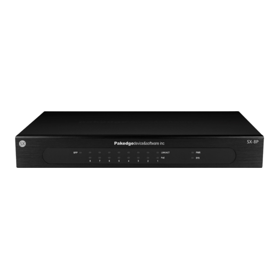
AV networks. CUSTOMER SERVICE AND TECHNICAL SUPPORT Pakedge Device & Software, Inc. is committed to providing you with exceptional support on all of our products. If you wish to speak with one of our representatives, you may contact us at: Customer Service Email: customerservice@pakedge.com... - Page 6 GETTING TO KNOW YOUR PRODUCT Package contents: SX Series switch • Power cord • • Quick Start Guide Console cable • Mounting Kit (2 side brackets, 1 face bracket, screws) • The front panel of the SX switches has several blue LEDs. See Table1 below for more information. Table 1: Front panel LED explanation from left to right.
- Page 7 The rear panel of the SX Series switches provides all inputs for a clean installation. See Table 2 below for more information. Table 2: Rear panel port connection explanation from left to right. Input Description Power Power adapter input Ports 1-8 RJ45 PoE/PoE+ ports SFP Port 1G SFP port...
-
Page 8: Accessing The Switch
Mozilla Firefox as your web browser. If you are using Internet Explorer, please use version 9 or newer. 5. Enter the default username pakedge and password pakedges. Click Login. Important: It is recommended that you change this default password. -
Page 9: Dashboard
DASHBOARD The dashboard provides frequently used quick links to help with more efficient setup. SYSTEM The System section contains the three sub sections System Settings, Security and Time Range Management, each of will be covered next. -
Page 10: Basic Settings
BASIC SETTINGS The System Settings page’s Basic Settings page will display the System Description, firmware version, serial number, and system up time. Below the system up time, you will also see the settings to use when consoling into the switch. Further down the basic settings page you will find additional settings. - Page 11 of the switch, enter a new IP address into the IP address field. You may also change the Subnet Mask and Gateway of the switch. Click Apply to finalize any setting changes you make on this page. The System Time page will display the current time. Use the Time Zone drop down menu to set the time zone.
- Page 12 The User Management page allows you to adjust settings to the user accounts that manage the switch. To change the password to the switch, enter the Current Password and then enter the New Password. You will need to Re-enter the new password. You can create a new user by selecting New under Multi-user Management Configuration.
- Page 13 The System Reboot page allows you to reboot the switch. Click Reboot System to perform a reboot. Security Protected Port page This setting allows the user to prevent the selected ports from communication with each other. Protected ports are allowed to communicate only with unprotected ports. No traffic will be allowed to pass between any two ports both set to “Protected”.
- Page 14 DoS page A Denial of Service (DoS) attack is an attempt to make a device unavailable to its users. DoS attacks saturate the device with external communication requests, so that it cannot respond to legitimate traffic. These attacks usually lead to a device CPU overload. The DoS protection feature is a set of predefined rules that protect the network from malicious attacks.
- Page 15 TCP SYN-RST Attack: Drops the packets with SYN and RST bits set. ICMP Fragment: Drops the fragmented ICMP packets. TCP- SYN: Drops SYN packets with sport less than 1024. TCP Fragment: Drops the TCP fragment packets with offset equals to one. Ping Max Size: Specify the maximum size of the ICMPv4/ICMPv6 ping packets.
-
Page 16: Ports
PORTS The Ports section contains three subsections. Each will be covered next. PORT SETTINGS Common Configuration page The Common Configuration page will allow you to change a port state or port speed. You can simply click on a port to select it (you can also select multiple ports) and then change the port State or Set Rate down below. - Page 17 Port Statistics page The port statistics page allows you to see statistics per port. Select a port from the drop down menu towards the top and you will see statistics such as received and sent bytes and even if there are errors on the port.
- Page 18 flow control feature is disabled. To change the state of flow control, select the ports you want to change and then change the State down below. Click Apply to finalize the settings.
- Page 19 Broadcast Storm The Broadcast storm page allows you to limit the amount of broadcast, multicast, or unicast data that is allowed to pass incoming per port. The Storm Control Global Setup allows you to modify how incoming traffic is calculated for storm control.
- Page 20 • Rate: Value of storm control rate, Unit: pps (packet per-second, range 1 - 262143) or Kbps (Kbits per-second, range16 - 1000000) depends on global mode setting. Unknown Multicast • State: Enable or Disable the storm control function of Unknown multicast packet. •...
- Page 21 the links fails, thus reliability could be maintained. Select the type of aggregation in the Aggregation type drop-down list. Static Aggregation For static aggregation, you must manually maintain the aggregation state of the member ports as system does not allow adding a new port or deleting any existing member port. Down to 2 member ports must be included in a single aggregation group.
- Page 22 To configure a LACP group, you first must select the aggregation algorithm. Select from the following algorithm options: MAC Address: Member ports in a link aggregation group share traffic load according to Source • and Destination MAC addresses. IP Address: Member ports in a link aggregation group share traffic load according to Source and •...
- Page 23 You can select multiple ports, and make the changes to the LACP timeout or port priority down below. Click Apply to finalize the settings. Static Aggregation To configure a static link aggregation group, you must first select the Aggregation Algorithm. Once you have selected the algorithm, click Apply.
-
Page 24: Poe
Once you have decided which sniffer mode to use, click the edit icon towards the right and then you will be able to select the ports that you want to mirror data for. The following image illustrates this. Click Apply to finalize the settings. Port: Selected port list State: Port EEE admin state: Enable: Enable EEE... - Page 25 You can select a port and then adjust the following settings below PoE Power Status: You can disable or enable PoE on the port • PoE Power Standard: You can select from 802.3af or 802.3at. 802.3af defines up to 15.4 watts •...
-
Page 26: Mac Control
MAC CONTROL The MAC Address Display page will allow you to view the different mac addresses passing through the ports on the switch. You can click on a port and see the mac address associated with that port. The following image illustrates this. After you have selected a port, you can click bind on a mac address entry and the switch will bind that mac address to the current port. -
Page 27: Vlans
along with the MAC Address. The following image illustrates an example of this. Click Add to add the entry. Under Show Static MAC info, you can see all existing Mac bindings on the switch. You can delete an entry by selecting the check box next to it and clicking Delete. VLANS A Virtual Local Area Network (VLAN) is a network topology which allows to logically instead of physically segment a LAN into several net segments. - Page 28 Enter the VLAN ID and Name for the VLAN and click Apply. You can continue adding VLANs in this manner. To add ports to a VLAN, click on the VLAN under Port Assignments. Note: All ports will belong to VLAN 1 by default.
- Page 29 You can also configure Hybrid ports in order to pass tagged VLAN traffic with one Primary Untagged VLAN on a port. You will need to add any additional VLANs you configured to the Hybrid ports. To do this, click the edit icon next to one of the Hybrid ports. There will be a blue outline around the box under the (U) column.
- Page 30 There will then be a blue outline around the box under the (T) column. The (T) indicates the VLANs that will have Tagged data. Click on the remaining VLANs to add them to the port. Click Apply. Repeat these steps for any other Hybrid ports you need to configure. If you need to add another Hybrid port, click the add symbol under the Hybrid section.
- Page 31 Inter-VLAN communication can only be achieved using a router or other layer 3 devices that are able to perform Layer 3 forwarding. The VLAN configuration page will allow you to use the Pakedge Zone Wizard to setup your different VLANs. Click on Start to begin the wizard.
- Page 32 Step 2: Select the ports you wish to add to each VLAN. For example, you can select ports 7 and 8 and then drag them to VLAN 2 to add both of those ports to that VLAN. The following image demonstrates this.
-
Page 33: Voice Vlan
After the VLAN wizard is complete, you will be taken to the advanced VLAN configuration page. VOICE VLAN Using Voice VLAN the switch is able to distinguish whether data is voice data or not according to the source MAC fields of the ingress packets. If the source MAC address conforms to the voice device’s OUI (Organizationally Unique Identifier) address, the packets will be regarded as voice data flow and the port which has received the voice data flow will automatically join the voice VLAN. - Page 34 Port Setup page Voice VLAN Security Mode: Set to enable or disable voice VLAN function. Voice VLAN Aging Time: Input value of aging time. Default is 1440 minutes. A voice VLAN entry will be aged out after this time without any activity. Voice VLAN ID: Select Voice VLAN ID.
-
Page 35: Traffic Menu
Select the ports that you would like to have the switch listen for voice data. If Voice data is detected, the port will be put into the Voice VLAN. Port: Select the port to apply configurations to. Voice VLAN Port Mode: Set Auto/Manual for Voice VLAN on an interface. Voice VLAN Port Status: Enable/disable the display of voice VLAN mode. -
Page 36: Qos
Quality of service is the ability to provide different applications, users, or data flows with different priority, or to guarantee a certain level of performance to a data flow. For example, a required bit rate, delay, jitter, packet dropping probability and/or bit error rate may be guaranteed. Quality of service guarantees are important if the network capacity is insufficient, especially for real-time streaming multimedia applications such as voice over IP, online games and IP-TV, since these often require fixed bit rate and are delay sensitive, and in networks where the capacity is a limited resource, for... - Page 37 • CoS-DSCP: Uses the trust CoS mode for non-IP traffic and trust DSCP mode for IP traffic. • IP Precedence: Traffic is mapped to queues based on the IP Precedence (first three bits of ToS field, although this has been depreciated for DSCP). The actual mapping of the IP precedence to queue can be configured on the IP Precedence mapping Port: Port name CoS: Port default CoS priority value for the selected ports...
- Page 38 Queue Scheduling page The switch supports eight queues for each interface. Queue number 8 is the highest priority queue. Queue number 1 is the lowest priority queue. There are two ways of determining how traffic in queues is handled, Strict Priority (SP) and Weighted Round Robin (WRR). Strict Priority (SP)—Egress traffic from the highest priority queue is transmitted first.
- Page 39 Queue: Queue ID to configure. Strict Priority: Set queue to strict priority type. WRR: Set queue to Weight Round Robin type. Weight: If the queue type is WRR, set the queue weight for the queue (1-127). WRR Bandwidth: Display of the WRR queue bandwidth percentage. CoS Mapping page The CoS Mapping table determines the egress queues of the incoming packets based on the 802.1p priority in their VLAN tags.
- Page 40 DSCP Mapping page The DSCP to Queue table determines the egress queues of the incoming IP packets based on their DSCP values. The original VLAN Priority Tag (VPT) of the packet is unchanged. Use the Queues to DSCP page to remark DSCP value for egress traffic from each queue. D: DSCP Priority Value in numbered format P: Priority, the CoS Priority level currently assigned to the DSCP value Priority: Set the selected DSCP Values with this CoS Priority level...
-
Page 41: Stp
IP Precedence Mapping page This page allows users to configure IP Precedence to Queue mapping and Queue to IP Precedence mapping. IP Precedence: IP Precedence value Queue: Select a Queue ID for the IP Precedence value The Spanning Tree Protocol (STP) is a network protocol that ensures a loop-free topology for any bridged Ethernet local area network. - Page 42 RSTP (Rapid Spanning Tree Protocol) provides significantly faster spanning tree convergence after a topology changes, introducing new convergence behaviors and bridge port roles to do this. RSTP is designed to be backwards-compatible with standard STP. RSTP is typically able to respond to changes within one second while STP can take 30 to 50 seconds to respond to a topology change.
- Page 43 STP Status: Enable/Disable the STP on the switch. STP Version: Specify the STP operation mode. • STP: Enable the Spanning Tree (STP) operation. • RSTP: Enable the Rapid Spanning Tree (RSTP) operation. Path Cost: Specify the path cost method. Long: Specifies that the default port path costs are within the range 1-200,000,000. •...
- Page 44 Priority: Specify the STP path cost on the specified port. Edge Port: Specify the edge mode. Enable: Force to true state (as link to a host). • Disable: Force to false state (as link to a bridge). • In the edge mode, the interface would be put into the Forwarding state immediately upon link up. If the edge mode is enabled for the interface and there are BPDUs received on the interface, the loop might be occurred in the short time before the STP state change.
-
Page 45: Igmp
IGMP IGMP Snooping page IGMP snooping is the process of listening to Internet Group Management Protocol (IGMP) network traffic. IGMP snooping, as implied by the name, is a feature that allows a network switch to listen to on the IGMP conversation between hosts and routers. By listening to the conversations between hosts and routers, the switch maintains a map of links which need IP multicast streams. - Page 46 Query Max Response Interval: In Membership Query Messages, it specifies the maximum allowed time before sending a responding report in units of 1/10 second. Last Member Query count: The count that Querier-switch sends Group-Specific Queries when it receives a Leave Group message for a group. Last Member Query Interval: The interval that Querier-switch sends Group-Specific Queries when it receives a Leave Group message for a group.
- Page 47 IGMP Querier VLAN: IGMP Snooping querier entry VLAN ID State: The IGMP Snooping querier Admin State. Operational Status: The IGMP Snooping querier operational status Querier Version: The IGMP Snooping querier operational version. Querier IP: The operational Querier IP address on the VLAN IGMP Querier VLAN Settings Edit Page VLAN: The Selected Edit IGMP Snooping querier VLAN List State: Set the enabling status of IGMP Querier Election on the chose VLANs...
- Page 48 Source-specific Group Query: IGMP Special Source and Group General Query packet Multicast Property Unknown Multicast Action: Set the unknown multicast action Drop: Drop the unknown multicast data. • Flood: Flood the unknown multicast data. • Router port: Forward the unknown multicast data to router port. •...
-
Page 49: Maintenance
MAINTENANCE The Management > Maintenance page will allow you to backup/restore configurations, perform firmware updates and factory reset the switch. To create a backup of your configuration, simply click Backup. To restore a configuration, click the icon and navigate to your configuration file. Click Restore. -
Page 50: Snmp
The Reset page will allow you to factory reset the switch. Simply click Reset System and the switch will then perform a factory reset. SNMP Simple Network Management Protocol (SNMP) is an OSI Layer 7 (Application Layer) designed specifically for managing and monitoring network devices. SNMP enables network management stations to read and modify the settings of gateways, routers, switches, and other network devices. -
Page 51: Lldp
Type: Notification Type Trap: Send SNMP traps to the host. • • Inform: Send SNMP informs to the host. Community: SNMP community name for notification. Trap Event Authentication Failure: SNMP authentication failure trap, when community not match or user authentication password not match. Link Up/Down: Port link up or down trap. - Page 52 LLDP Handling: Select LLDP PDU handling action to be filtered, bridging or flooded when LLDP is globally disabled. Filtering: Deletes the packet. • Bridging: (VLAN-aware flooding) Forwards the packet to all VLAN members. • Flooding: Forwards the packet to all ports •...
-
Page 53: Syslog
Age Outs: The number of times the complete set of information advertised by MSAP has been deleted from tables associated with the remote systems because the information timeliness interval has expired. Port: Interface or port number. Transmit Frame Total: Number of LLDP frames transmitted on the corresponding port. Receive Frame Total: Number of LLDP frames received by this LLDP agent on the corresponding port, while the LLDP agent is enabled. -
Page 54: Network Diagnostics
• Critical Level 3: Critical conditions. • Error Level 4: Error conditions. • Warning Level 5: Warning conditions. • Notice Level 6: Normal but significant conditions. Informational Level 7: Informational messages. • Debug Level 8: Debug-level messages. • The Log Setup page allows you to input a Syslog Server IP address to collect logs. Check the Enable Logging box. - Page 55 Ping page Destination IP Address: Specify the Hostname/IPv4/IPv6 address for the remote logging server. Sending Times: Specify the number of ICMP ping requests.
-
Page 56: Appendix A - Technical Support
APPENDIX A – TECHNICAL SUPPORT Please visit our website for up-to-date support information: Website: www.pakedge.com Email: support@pakedge.com CONTACT INFORMATION: Pakedge Device & Software Inc. 11734 Election Road Draper, UT 84020... -
Page 57: Appendix B - Specifications
APPENDIX B – SPECIFICATIONS Item Specification Input voltage 100 – 240VAC 50/60 Hz 6A Power consumption 8x RJ45 10/100/1000 auto-sensing Giga switching ports with Interface PoE/PoE+ output 1x 1000 Mbps SFP port PoE power budget 125W Management interface 1x Console port 0°C ~ 40°C Operating temperature -40°... - Page 58 1. ARP attack defense, worm attack defense, DoS attack Safety defense and MAC attack defense; 2. Interface isolation; 1. 802.1P port trust mode; 2. IP DSCP port trust mode; 3. IP Precedence port trust mode; 4. Bandwidth control; 5. Up to 8-queue QoS mapping; Firmware/Configuration Upgrade TFTP (Trivial File Transfer Protocol) 1.
-
Page 59: Appendix C - Limited Warranty
Product, even if Pakedge has been advised of the possibility of such damages. - Page 60 PERFORMANCE YOUR PAKEDGE PRODUCT IS CAPABLE OF PROVIDING. Rights, Limits, and Exclusions Pakedge limits its obligation under any implied warranties under state laws to a period not to exceed the warranty period. There are no express warranties. Pakedge also excludes any obligation on its part for incidental or consequential damages related to the failure of this product to function properly.
- Page 61 11734 Election Road Draper, UT 8402045 U.S.A Visit Us At: www.pakedge.com © Pakedge Device & Software Inc. 2017 – All Rights Reserved DOC-00251-C 2017-06-19 MS...
Need help?
Do you have a question about the SX-8P and is the answer not in the manual?
Questions and answers