Table of Contents
Advertisement
Advertisement
Table of Contents

Related Manuals for Pakedge S3L-24P


Summary of Contents for Pakedge S3L-24P
- Page 1 S3L-24P Layer 3 Lite Managed Switch Hardware Installation Guide...
-
Page 2: Table Of Contents
Table of Contents Intended readers ........................................1 Audience ..........................................1 Other documentation ....................................1 Typographical conventions ..................................1 Style format conventions.................................... 1 Icon conventions ......................................1 Introduction ..........................................2 Switch description ......................................2 Package contents ......................................2 Switch components ......................................3 Front panel components.................................... -
Page 3: Intended Readers
This guide is intended for network administrators and other IT networking professionals responsible for installing and maintaining this switch. The S3L-24P will simply be referred to as the switch within this guide. This guide is written in a way that assumes that users already have the experience and knowledge of Ethernet and modern networking principles for Local Area Networks. -
Page 4: Introduction
Introduction Switch description The S3L-24P Layer 3 Lite Managed Switch is targeted for the deployment in Small-to-Medium Businesses (SMB) providing 10 Gbps Ethernet wire-speed connections that can be used to uplink servers or to interconnect switches within the LAN. For medium-to-large scale enterprise deployment, these switches provide an excellent means to interconnect edge switches and core switches. -
Page 5: Switch Components
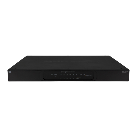
S3L-24P Layer 3 Lite Managed Switch Hardware Installation Guide Switch components In this chapter we’ll discuss the physical components that can be found on the front, side, and back panels of this switch. Front panel components The front panel of this switch features only LED indicators and no physical ports or buttons. -
Page 6: Back Panel Components
S3L-24P Layer 3 Lite Managed Switch Hardware Installation Guide LED Indicator Color Behavior Description (Copper Ethernet No active connection or port disabled. Ports) Amber Solid Light Secure 10/100/1000 Mbps connection is active and power is being supplied to the device in the port. -
Page 7: Side Panel Components
S3L-24P Layer 3 Lite Managed Switch Hardware Installation Guide Side panel components The side panels of this switch feature the following components. Figure 5 Side panels The following table lists the components found on the side panels of the switch. -
Page 8: Hardware Installation
S3L-24P Layer 3 Lite Managed Switch Hardware Installation Guide Hardware installation Installation guidelines This section will discuss the hardware installation guidelines that administrators must follow in order to properly and safely install this switch into the appropriate environment. Note: Please read through the Safety Instructions chapter before starting any installation discussed in this chapter. - Page 9 S3L-24P Layer 3 Lite Managed Switch Hardware Installation Guide The figure below illustrates how to complete the rack-mount installation. 5. Use the rack-mount unit screws and the additional screwdriver to fasten the frontal rack-mount brackets onto the front of the rack-mount unit.
-
Page 10: Installing Transceivers Into The Transceiver Ports
S3L-24P Layer 3 Lite Managed Switch Hardware Installation Guide Installing transceivers into the transceiver ports This switch supports 4 SPF+ 10 Gbps ports. SFP+ technology allows a smooth transition from 1 to 10 Gigabit Ethernet infrastructures in switches. This switch supports both fiber and copper cabling solutions. -
Page 11: Software Features
S3L-24P Layer 3 Lite Managed Switch Hardware Installation Guide Software features This switch supports the following software features. Layer 2 features Category Feature Layer 2 table • MAC address table (up to 16K entries). • Dynamic address learning • Layer 2 Unicast/Multicast •... -
Page 12: Service Access Control
S3L-24P Layer 3 Lite Managed Switch Hardware Installation Guide Category Feature • IGMP snooping proxy mode and transparent mode • IGMP query • Link Layer Discovery Protocol (LLDP) • Link Layer Discovery Protocol Media Endpoint Discovery extension (LLDP-MED) Service access control... -
Page 13: Management Information Base (Mib)
S3L-24P Layer 3 Lite Managed Switch Hardware Installation Guide Category Feature • Dos attack prevention • DHCP client (IPv4/IPv6) • DHCP relay (with Option 82) • DHCP Server (IPv4) ○ Supports 8 default routers, 8 WINS servers, 1024 address pools, and 1024 clients •... - Page 14 Command Line Interface, refer to the S3L-24P Layer 3 Lite Managed Switch Command Line Interface Guide. Note: For more information about how to configure and monitor the software features of this switch using the Web User Interface, refer to the S3L-24P Layer 3 Lite Managed Switch Web User Interface Guide.
-
Page 15: Technical Specifications
NK-1 Wireless Controller User Guide Technical specifications Product specifications The following tables list the product specifications for this switch. Category Specification Description Physical Form factor 1 RU fixed form factor Physical ports 24 copper PoE ports (10/100/1000 Mbps) 4 SFP+ module ports (1/10 Gbps) Performance Switching capacity 128 Gbps... -
Page 16: Safety Instructions
NK-1 Wireless Controller User Guide Category Specification Description 0°C to 45°C (32°F to 113°F) Operating temperature -20°C to 70°C (-4°F to 158°F) Storage temperature Operating relative humidity 10% to 90% (non-condensing) Storage relative humidity 0% to 95% (non-condensing) Altitude 0 to 2,000 meters (0 to 6,562 feet) Safety instructions The following sections provide safety precautions to follow when installing the switch. -
Page 17: Rack-Mount Safety Precautions
• The mounting brackets provided must be used to securely mount the device in a rack- mount unit. Ordering information Part number Description S3L-24P S3L-24P Layer 3 Lite Managed Switch. 24 copper PoE ports with 10/100/1000Mbps wire-speeds. 4 SFP+ module ports with 1/10 Gbps wire-speeds. - Page 18 Copyright ©2017, Control4 Corporation. All rights reserved. Control4, the Control4 logo, Pakedge, and BakPak are registered trademarks or trademarks of Control4 Corporation or its subsidiaries in the United States and/or other countries. All other names and brands may be claimed as the property of their respective owners.
Need help?
Do you have a question about the S3L-24P and is the answer not in the manual?
Questions and answers