
Related Manuals for Lifetime 60058


Summary of Contents for Lifetime 60058
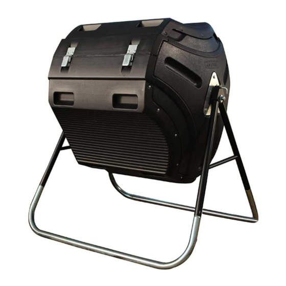
- Page 1 OUTDOOR STORAGE MODEL N° 60058 OWNER’S MANUAL Keep this Identification Number in case you must contact our Customer Service Department.
-
Page 2: Safety Instructions
REGISTER YOUR LIFETIME PRODUCT TODAY! There are benefi ts to registering your Lifetime product. With our new online product registration form, it’s fast and easy! Register with us at www.lifetime.com and enjoy these great benefi ts: promotions! But you will need to provide a sales receipt to verify your product purchase date before warranty service will be provided. -
Page 3: Before Beginning Assembly
BEFORE BEGINNING ASSEMBLY *Two adults required to complete assembly* *Two adults required to complete assembly* Only adults should set up the product. Do not allow children in the set-up area until assembly is complete. TOOLS AND PARTS REQUIRED FOR THIS ASSEMBLY Socket Wrench Rubber Mallet #2 Phillips... - Page 4 ASSEMBLY GUIDES Refer to the following areas throughout the instructions to assist in the assembly process: This area is located at the top, left-hand TOOLS AND HARDWARE REQUIRED FOR THIS PAGE corner of the page and indicates which tools and hardware are needed to complete the assembly steps on a page.
-
Page 5: Parts & Hardware List
PARTS & HARDWARE LIST MAIN COMPOSTER PARTS Description HARDWARE BAG Description TUMBLER ASSEMBLY HARDWARE COMPOSTER PARTS KIT BASE ASSEMBLY HARDWARE PARTS IDENTIFIER Main Composter Parts Ventilation Tube... - Page 6 PARTS IDENTIFIER Main Composter Parts Composter Parts Kit [BIV] WARNING spinning Tumbler. Failure to heed this warning Hinge Tube Pinned Hinge...
-
Page 7: Hardware Identifier
HARDWARE IDENTIFIER Tumbler Assembly Hardware [BIS] Blow Hole Plug Sleeve Black Plastic Spacer Base Assembly Hardware [BIT]... - Page 8 BASE FRAME ASSEMBLY HARDWARE REQUIRED HARDWARE BAG REQUIRED: BIT SMALL PARTS REQUIRED PARTS REQUIRED TOOLS REQUIRED Safety Glasses Phillips Screwdriver 7/16” Wrench Electric Drill w/Phillips Head...
- Page 9 TOOLS AND HARDWARE REQUIRED FOR THIS PAGE NO HARDWARE REQUIRED FOR THIS STEP 2 ADULTS REQUIRED FOR THIS STEP BASE ASSEMBLY Set the two A-Frame Weldments (BII) positions shown, insert a Composter Leg (BIH) Repeat this step for the second Composter Leg.
- Page 10 TOOLS AND HARDWARE REQUIRED FOR THIS PAGE #8 x 1/2” Phillips Self-Tapping Screws (BHJ) upright. Do not overtighten Screws.
- Page 11 TOOLS AND HARDWARE REQUIRED FOR THIS PAGE Slide the Locking Pin Spring (BIN) up and over the Locking Pin Assembly (BIX) as shown. WARNING spinning Tumbler. Failure to heed this warning...
- Page 12 TOOLS AND HARDWARE REQUIRED FOR THIS PAGE 7/16” One by one, place the two Inner Housing Brackets (BIJ) 1/4” x 1 1/2” Carriage Bolt (ABU) 1/4” Cap Nut (ADJ) for Bracket. Locking Pin WARNING the Bolt breaks through the plastic cap, call our on the end of the Bolt may cause serious injuries.
-
Page 13: Hardware Required
TUMBLER ASSEMBLY HARDWARE REQUIRED HARDWARE BAG REQUIRED: BIS Blow Hole Plug Sleeve Black Plastic Spacer SMALL PARTS REQUIRED Pinned Hinge Hinge Tube... -
Page 14: Parts Required
TUMBLER ASSEMBLY (CONT.) PARTS REQUIRED Ventilation Tube TOOLS REQUIRED 3/4” Wrench Phillips Screwdriver Safety Glasses Rubber Mallet Socket Wrench with 1/2” & 3/4” Sockets 1/8” Drill Bit (ARA) (Included) Electric Drill w/Phillips Head... - Page 15 TOOLS AND HARDWARE REQUIRED FOR THIS PAGE NO HARDWARE REQUIRED FOR THIS PAGE Using an electric drill and the 1/8” Drill Bit (ARA) Panel/ Lid (BHN) as shown. Do not drill through the edges of the third Panel/Lid (BHN). Note: Do not drill through the edges of the third Panel/Lid (BHN).
- Page 16 TOOLS AND HARDWARE REQUIRED FOR THIS PAGE NO HARDWARE REQUIRED FOR THIS PAGE Using an electric drill and the 1/8” Drill Bit (ARA) Panels (BHN) as shown.
- Page 17 TOOLS AND HARDWARE REQUIRED FOR THIS PAGE 1/2” TUMBLER ASSEMBLY Mounting End Plate (BHP) with the warning sticker to an End Panel (BHM) with the warning sticker just below 5/16” x 3/4” Carriage Bolts (BIR) 5/16” Steel Flat Washers (BHO) 5/16”...
- Page 18 TOOLS AND HARDWARE REQUIRED FOR THIS PAGE 2 3/4” Slide a 1/2” Flat Washer (BIO), Sleeve (BIL), and 5/8” Flat Washer (BIP) over a 1/2” x 2 3/4” Hex-Head Bolt (BIK). Tear open the Grease Packet (AKH) Repeat steps 2.4 - 2.5 for the second set of Washers, Bushing, Sleeve, and Hex Bolt.
- Page 19 TOOLS AND HARDWARE REQUIRED FOR THIS PAGE Bolt, Washer, and Sleeve Assembly as shown. Be sure to insert a Black Plastic Spacer (BIM) between the End Panel and the Inner Housing Bracket of the A-Frame as shown. Warning Sticker Bolt, Washer, and Sleeve Assembly...
- Page 20 TOOLS AND HARDWARE REQUIRED FOR THIS PAGE 3/4” 3/4” Repeat steps 2.6 - 2.7 for the second End Panel.
- Page 21 2 ADULTS REQUIRED FOR THIS STEP Orient the second End Panel to match the first to align the two ventilation holes. Have another adult hold this second Panel in place. Locking Pin Lifetime Logo Note: These two ventilation holes must be aligned.
- Page 22 TOOLS AND HARDWARE REQUIRED FOR THIS PAGE 2 ADULTS REQUIRED FOR THIS STEP Place one of the Panels/Lids (BHN) #10 x 3/4” Phillips Pan-Head Screws (ADW) until the It’s OK if the Screws (ADW) spin freely at this point. Do not worry about stripping the plastic.
- Page 23 TOOLS AND HARDWARE REQUIRED FOR THIS PAGE NO HARDWARE REQUIRED FOR THIS PAGE 2.10 Ventilation Tube (BHQ) as shown. Ventilation Hole Lifetime Logo...
- Page 24 TOOLS AND HARDWARE REQUIRED FOR THIS PAGE 2 ADULTS REQUIRED FOR THIS STEP Slide a hook of the Double Hook Straps (BJC) into each of the recesses at the end of the other Panel/Lid (BHN) (Fig. 2.11 (Fig. 2). Fig. 1 Fig.
- Page 25 TOOLS AND HARDWARE REQUIRED FOR THIS PAGE 2.12 #10 x 3/4” Phillips Pan-Head Screws (ADW) until the heads of the Screws are flush with Straps. It’s OK if the Screws (ADW) spin freely at this point. Do not worry about stripping the plastic. Plastic Nuts (BHK).
- Page 26 TOOLS AND HARDWARE REQUIRED FOR THIS PAGE #10 x 3/4” 2.13 Phillips Pan-Head Screws (ADW) It’s OK if the Screws (ADW) spin freely at this point. Do not worry about stripping the plastic. Repeat this step for the other side of the Front Panel/Lid. (10) Plastic Nuts (BHK), but do not overtighten.
- Page 27 TOOLS AND HARDWARE REQUIRED FOR THIS PAGE Set two Latch Assemblies (BJA) 2.14 #10 x 3/4” Phillips Pan- Head Screw (ADW) It’s OK if the Screws (ADW) spin freely at this point. Do not worry about stripping the plastic. Finally, on the inside of the Tumbler, secure the Plastic Nuts (BHK).
- Page 28 TOOLS AND HARDWARE REQUIRED FOR THIS PAGE On the other side of the Tumbler, set two Pinned Hinges (BIY) in the locations shown and align the holes in the 2.15 #10 x 3/4” Phillips Pan-Head Screws (ADW) into the holes of each Pinned Hinge until the heads of the Screws are flush with the Pinned Hinges.
- Page 29 TOOLS AND HARDWARE REQUIRED FOR THIS PAGE Place two Hinge Tubes (BJB) onto the Lid (BHN) 2.16 #10 x 3/4” Phillips Pan-Head Screws (ADW). It’s OK if the Screws (ADW) spin freely at this point. Do not worry about stripping the plastic. Finally, place a Plastic Nut (BHK) over each Screw Tighten the Screws (ADW) into the Plastic Nuts (BHK) with a screwdriver only.
- Page 30 TOOLS AND HARDWARE REQUIRED FOR THIS PAGE Blow Hole Plug (BTK) into each hole in the Front Panel. Twist the Blow Hole Plug as you insert it. Continue 2.18 inserting the Plug until the end with the larger diameter is flush with the surface of the Panel. Repeat this step for the other Panels.
- Page 31 TOOLS AND HARDWARE REQUIRED FOR THIS PAGE NO HARDWARE REQUIRED FOR THIS STEP 2.19 Note: Remove Lid when filling and emptying Tumbler.
- Page 32 TOOLS AND HARDWARE REQUIRED FOR THIS PAGE NO HARDWARE REQUIRED FOR THIS STEP LOCKING THE COMPOSTER as shown. Latch Hook Latch Assembly wire Repeat steps 3.1 - 3.2 for second Latch. WARNING spinning Tumbler. Failure to heed this warning...
- Page 33 LIFETIME COMPOST TUMBLERS 5-YEAR LIMITED FACTORY WARRANTY THE MANUFACTURER RESERVES THE RIGHT TO MAKE SUBSTITUTIONS TO WARRANTY CLAIMS IF PARTS ARE UNAVAILABLE OR OBSOLETE. does not cover defects due to improper installation, alteration or accident. This warranty does not cover damage caused no cost to the purchaser.
- Page 34 ® ENHANCE YOUR LIFETIME PURCHASE BY ADDING ACCESSORIES OR OTHER GREAT PRODUCTS To purchase accessories or other Lifetime Products, visit us at: www.lifetime.com Or call: 1-800-424-3865...
Need help?
Do you have a question about the 60058 and is the answer not in the manual?
Questions and answers