Table of Contents
Advertisement
Quick Links
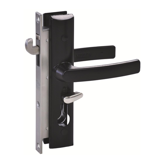
8654 Hinged Security Door Lock
3 Point Kit and Standard Lock Installation
1
'o'
Ring
Top
Locating Lugs
Lug
Actuator Bar
Rod
Fitting the Actuator Bar and Auxiliary Locks
Note: For ease of fitment remove door from the door frame.
- Assemble the Actuating Bar and Rods as shown prior to
fitting to the door stile. With the "TOP" mark facing the front.
- Keep the locating lugs of the Actuating Bar facing the front edge of
the door.
- Insert the Actuator Bar and rod assembly through the top cut-out
and slide it through the door stile.
- With the Auxiliary locks in the locked position (as shown),
Important: Connect the top Auxiliary lock first to the end of the rod
followed by the bottom Auxiliary lock.
- Then push them both into the door stile.
2
Top
Fitting Central Lock
Auxiliary
With the central lock in the factory set Deadlock position,
Lock
insert into the stile. Locate and engage the lug on
the Actuating Bar with the lock, then secure with screws.
Important: The lock must be installled in the position shown,
product warranty cannot be assured if installed upside down.
3
Stile
Cam
Fitting Cylinder & Spindle
- Insert cylinder so cam turns towards front of door.
- Losely fix cylinder with screw.
- Then insert spindle into lock body.
4
Lever Handing
If necessary prepare escutcheon by rotating levers 180 degrees
downwards to required handing position.
5
Bottom
Auxiliary
Lock
Fitting Escutcheon
- Fit escutcheon with snib on the inside face of the door.
- Ensure snib is to 90 degrees in the direction of the lever..
- Secure inside and outside escutcheons with screws and
screw hole plugs.
6
Passage Mode
With the central lock in the factory set Deadlock position, insert key
and rotate 90 degrees away from the lever to the unlocked position
or Passage mode. Snib rotates to the vertical position.
Spindle
7
Hook
bolt
retracted
Cylinder
Drilling Hole in Top and Bottom Auxiliary Locks
- Gently push the top Auxiliary lock upwards to retract the hook bolt.
- Then drill a 3mm hole in the centre of the slotted hole.
- Repeat this step for the bottom Auxiliary lock.
8
Snib
Fixing Screw to Top and Bottom Auxiliary Locks
- Gently push the top Auxiliary lock upwards to retract the hook bolt.
- Lightly fix screw in slotted hole.
- Repeat this step for the bottom Auxiliary lock.
9
Depress Release
Release
Button
Button
Test Safety Mode:
Important: Release button above hook bolt must be depressed.
Rotate key or snib 90 degrees towards the lever:
- Padlock symbol is visible.
- Inside and outside levers are locked.
- Auxiliary hook bolts are thrown and locked, push hook bolts upwards
to check.
- Repeat STEP 6 to return lock to Passage mode.
10
Depress Release
Release
Button
Button
Test Deadlock Mode:
Important: Release button above hook bolt must be depressed.
Rotate key 180 degrees towards the lever:
- Snib rotates 90 degrees towards the lever, padlock symbol is visible.
- Inside and outside levers are locked.
- Auxiliary hook bolts are thrown and locked, push hook bolts upwards
to check.
11
Important: Reposition top and bottom Auxiliary locks if
necessary to achieve Safety and Deadlock modes, then
fully tighten fixing screws in STEP 8.
12
Securing Top and Bottom
Auxiliary Locks
Drill a 3mm hole through bottom hole
in the Auxiliary locks, secure with
fixing screws.
Advertisement
Table of Contents

Related Manuals for Assa Abloy 8654


Summary of Contents for Assa Abloy 8654
- Page 1 8654 Hinged Security Door Lock Depress Release Release Button Button 3 Point Kit and Standard Lock Installation Fitting Central Lock Auxiliary With the central lock in the factory set Deadlock position, ‘o’ Lock insert into the stile. Locate and engage the lug on Ring the Actuating Bar with the lock, then secure with screws.
- Page 2 8654 Hinged Security Door Lock Mounting handle BELOW centreline of door Mounting handle ABOVE centreline of door Timber Door Central Strike Installation Timber Door Auxiliary Strike Installation (Standard 19mm door) (Standard 19mm door) Slot (min) Slot (min) Door jamb Door jamb...
Need help?
Do you have a question about the 8654 and is the answer not in the manual?
Questions and answers