Table of Contents
Advertisement
Available languages
Available languages
Riegel
Bolt
Türriegel Modell 843ZY
Produktname
Door Bolt Model 843ZY
Produktname
Installations- und Montageanleitung
Installations- und Montageanleitung
Installation and mounting instructions
D0122301
DXXXXXNN
www.assaabloy.de
DE Seite
DE Seite
EN Page
EN Page
FR Page
IT Pagina 60
NL Pagina 60
The global leader in
ASSA ABLOY, the global leader
door opening solutions
in door opening solutions
2
2
22
20
40
Advertisement
Chapters
Table of Contents

Related Manuals for Assa Abloy effeff 843ZY


Summary of Contents for Assa Abloy effeff 843ZY
- Page 1 NL Pagina 60 Produktname Türriegel Modell 843ZY Produktname Door Bolt Model 843ZY Installations- und Montageanleitung Installations- und Montageanleitung Installation and mounting instructions The global leader in ASSA ABLOY, the global leader DXXXXXNN D0122301 door opening solutions in door opening solutions...
- Page 2 Dokumentennummer, -datum D0122301 03.2020 Copyright © 2020, ASSA ABLOY Sicherheitstechnik GmbH Diese Dokumentation einschließlich aller ihrer Teile ist urheberrechtlich geschützt. Jede Verwertung bzw. Veränderung außerhalb der engen Grenzen des Urheberrechtsgesetzes ist ohne Zustimmung von ASSA ABLOY Sicherheitstechnik GmbH unzulässig und strafbar.
-
Page 3: Table Of Contents
Inhaltsverzeichnis Produktinformation........4 Der Türriegel 843ZY ............4 Hinweise . -
Page 4: Produktinformation
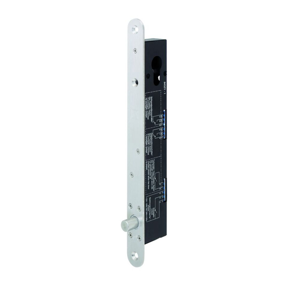
Produktinformation Der Türriegel 843ZY Der elektrische Türriegel 843ZY (Abb. 1) dient zur (zusätzlichen) Verriegelung einer Tür. Er wurde werkseitig für den Arbeitsstrom- oder Ruhestrombetrieb konfigu- riert. Der Türriegel kann jederzeit über einen Schließzylinder bedient werden. Der Türriegel ist mit magnetischen und elektronischen Überwachungssensoren ausgestattet, zum Anschluss einer Alarmanlage, zur Kontrolle für eine Ablaufsteu- erung des Türverschlusses oder zum Anschluss an ein Zutrittskontrollsystem. -
Page 5: Hinweise
Hinweise Zu dieser Anleitung Diese Installations- und Montageanleitung wurde für Handwerksfachkräfte, sowie eingewiesenes Personal geschrieben. Lesen Sie diese Anleitung, um das Gerät sicher zu installieren, zu betreiben und die zulässigen Einsatzmöglichkeiten, die es bietet, auszunutzen. Die Anleitung gibt Ihnen auch Hinweise über die Funktion wichtiger Bauteile. Bedeutung der Symbole Gefahr! Sicherheitshinweis: Nichtbeachtung führt zu Tod oder schweren Verletzungen. -
Page 6: Sicherheitshinweise
Gewerks oder eingewiesene Personen ausgeführt werden. Der Türriegel kann in einer passend gefrästen oder gesägten Schlosstasche montiert werden. Mit dem von ASSA ABLOY Sicherheitstechnik angebotenen Zubehör kann der Türriegel auch aufliegend montiert werden. An Glastüren muss der Türriegel aufliegend in einem geeigneten Aufbaugehäuse montiert werden. -
Page 7: Funktionen
Funktionen Verriegeln und Entriegeln Der Türriegel verriegelt automatisch. Bei einem elektrischen Impuls zum Entriegeln, wird für mehrere Sekunden entriegelt. Die Dauer wird über DIP-Schalter eingestellt („DIP-Schalter S1 und S2“, Seite 12). Wird die Tür innerhalb dieser Zeitspanne geöffnet, bleibt der Riegel im Zustand entriegelt. -
Page 8: Montage
Montage Montage mit Aufbaugehäuse Türriegel an der Zarge – Schraubmontage Montage... - Page 9 Schließblech auf dem Glastürblatt - Klebemontage Montage...
-
Page 10: Bündige Montage In Schlosstasche
Bündige Montage in Schlosstasche... -
Page 11: Funktionsprüfung
Funktionsprüfung Nach Montage in Schlosstasche Nach Montage in Aufbaugehäuse Elektrischer Anschluss... -
Page 12: Elektrischer Anschluss
Elektrischer Anschluss DIP-Schalter Zum Umstellen der DIP-Schalter muss die Abdeckung am Türriegel entfernt werden (Abb. 2). Abb. 2 : DIP-Schalter – Abdeckung am Türriegel entfernen DIP-Schalter S1 und S2 Über die DIP-Schalter S1 und S2 wird die Entriegelungsdauer eingestellt (Tab. 1). Sekunden DIP S1 DIP S2... -
Page 13: Anschlüsse
Anschlüsse Der Türriegel muss an ein Schaltnetzteil angeschlossen werden (Abb. 3) . Alle anderen Anschlüsse sind optional. Steuereingang Bei einer Spannungsversorgung ohne Nutzung des Steuereingangs (Abb. 3) kann der Ruhestrombetrieb nicht verwendet werden. Abb. 3 : Anschlüsse 12-24 V DC Funktion Spannungsversorgung Steuereingang... -
Page 14: Spannungsversorgung
Spannungsversorgung Steuereingang angeschlossen Abb. 4: Anschluss mit bei Ruhestrombetrieb Nutzung des Steuereingang Spannungs- versorgung 12-24 V DC bei Arbeitsstrombetrieb Spannungs- versorgung 12-24 V DC Elektrischer Anschluss... - Page 15 Steuereingang nicht angeschlossen Abb. 5: Anschluss ohne bei Ruhestrombetrieb Nutzung des Steuereingangs Spannungs- versorgung 12-24 V DC Elektrischer Anschluss...
-
Page 16: Technische Daten
Technische Daten Eigenschaft Ausprägung Tab. 3: Mechanisch Material: Verriegelungsbolzen, Stulp Edelstahl SS304 und Schließblech Schließzyklen 1.000.000 Funktionsluft 6 mm Haltekraft 10.000 N Eigenschaft Ausprägung Tab. 4: Elektrisch Spannungsversorgung 12 V DC bis 24 V DC ±15 % maximale Stromaufnahme bei 12 V DC 24 V DC ·... -
Page 17: Zertifizierungen
Betrieb Störungen des Rundfunk- und Fernsehempfangs verursachen. Der Betrieb dieses Produkts in einem Wohngebiet kann schädliche Interferenzen verursachen. In diesem Fall muss der Betreiber auf eigene Kosten Abhilfe schaffen. CE-Kennzeichnung ASSA ABLOY Sicherheitstechnik GmbH Bildstockstraße 20 72458 Albstadt DEUTSCHLAND... -
Page 18: Maße
Maße Abb. 6: Türriegel Türriegel und Schließblech 24,2 12,5 12,5 Schließbleche 12,5 12,5 Ø15,5 12,5 12,5 89,5 Ø15,5 Technische Daten... - Page 19 Abb. 7: Aufbaugehäuse - für Tierriegel Optional Zubehör 19,5 19,5 M5 x 0,8 Aufbaugehäuse - für Schließgegenstück 19,5 19,5 M5 x 0,8 Türschild zum Aufkleben auf Rückseite einer Glastür Technische Daten...
-
Page 20: Zubehör, Wartung, Gewährleistung, Entsorgung
Zyklen für eine regelmäßige Funktionskontrolle einzuhalten. Details dazu müssen mit der zertifizierende Behörde abgestimmt werden. Gewährleistung Es gelten die gesetzlichen Gewährleistungsfristen und die Verkaufs- und Lieferbe- dingungen der ASSA ABLOY Sicherheitstechnik GmbH (www.assaabloy.de). Entsorgung Verpackungsmaterialien müssen der Wiederverwendung zugeführt werden. WEEE-Reg.-Nr. DE 69404980 Das Produkt ist nach dem Gebrauch als Elektronikschrott ordnungsgemäß... - Page 22 D0122301 03.2020 Copyright © 2020, ASSA ABLOY Sicherheitstechnik GmbH This document and all its parts are copyrighted. Any use or changes outside the strict limits of the copyright are prohibited and liable to prosecution unless prior consent has been obtained from ASSA ABLOY Sicherheitstechnik GmbH .
- Page 23 Table of contents Product information ........24 Door bolt 843ZY .
-
Page 24: Product Information
Product information Door bolt 843ZY The electric 843ZY door bolt (Fig. 1) is used for (additional) locking of a door. It was configured for fail-locked or fail-unlocked operation at the factory. The door bolt can be operated at any time via a locking cylinder. The door bolt is equipped with magnetic and electronic monitoring sensors for connecting an alarm system, as monitoring for a sequence control system of the door lock or for connecting an EAC system. -
Page 25: Notes
Notes About this manual This installation and mounting manual was written for qualified technicians and trained personnel. The manual was designed to enable you to install and operate the device safely and make full use of the permitted range of applications the control terminal has to offer. -
Page 26: Safety Instructions
The door bolt can be mounted in a suitably milled or sawn lock pocket. The door bolt can also be surface-mounted with the accessories offered by ASSA ABLOY Sicherheitstechnik. On glass doors, the door bolt must be surface-mounted in a suitable surface-mounted casing. -
Page 27: Functions
Functions Locking and unlocking The door bolt locks automatically. The door bolt is unlocked for several seconds when an electrical unlock impulse is received. The duration is set via a DIP switch („DIP switch S1 and S2“, page 32). If the door is opened within this time, the bolt remains in the unlocked state. The door bolt locks again when the door is closed. -
Page 28: Mounting
Mounting Mounting with surface-mounted casing Door bolt on the door frame – screw mounting Mounting... - Page 29 Striking plate on the glass door leaf - adhesive mounting Mounting...
-
Page 30: Flush Mounting In The Lock Pocket
Flush mounting in the lock pocket... -
Page 31: Function Check
Function check After mounting in lock pocket After mounting in surface-mounted casing Electrical connection... -
Page 32: Electrical Connection
Electrical connection DIP switch The cover on the door bolt must be removed for switching the DIP switch (Fig. 2). Fig. 2 : DIP switch – remove cover on the door bolt DIP switch S1 and S2 The unlock period is set via the DIP switches S1 and S2 (Tab. 1). Seconds DIP S1 DIP S2... -
Page 33: Connections
Connections The door bolt must be connected to a switch mains receiver (Fig. 3). All other connections are optional. Control input For a power supply without using the control input (Fig. 3), fail-unlocked operation can not be used. Fig. 3 : Connections 12-24 V DC No. -
Page 34: Power Supply
Power supply Control input connected Fig. 4: Connection using during fail-unlocked operation the control input Power- supply 12-24 V DC during fail-locked operation Power- supply 12-24 V DC Electrical connection... - Page 35 Control input not connected Fig. 5: Connection during fail-unlocked operation without using the control input Power- supply 12-24 V DC Electrical connection...
-
Page 36: Technical Data
Technical data Feature Characteristic Tab. 3: Mechanical Material: Locking bolt, face plate and Stainless steel SS304 striking plate Locking cycles 1,000,000 Rebate gap 6 mm Holding force 10,000 N Feature Characteristic Tab. 4: Electrical Power supply 12 V DC to 24 V DC ±15 % Maximum current consumption at 12 V DC 24 V DC... -
Page 37: Certifications
Operation of this product in a residential area can cause harmful interferences. In this case, the operator must implement a remedy at his own cost. CE mark ASSA ABLOY Sicherheitstechnik GmbH Bildstockstraße 20 72458 Albstadt GERMANY... -
Page 38: Dimensions
Dimensions Fig. 6: Door dead bolts Door bolt and striking plate 24,2 12,5 12,5 Striking plates 12,5 12,5 Ø15,5 12,5 12,5 89,5 Ø15,5 Technical data... - Page 39 Fig. 7: Surface-mounted casing - for door bolt Optional accessories 19,5 19,5 M5 x 0,8 Surface-mounted casing - for locking counterpart 19,5 19,5 M5 x 0,8 Door escutcheon for sticking on the rear side of a glass door Technical data...
-
Page 40: Accessories, Maintenance, Warranty, Disposal
Accessories, maintenance, warranty, disposal www.assaabloy.de Maintenance The 843ZY door bolt is permanently lubricated ex works. Relubrication renders the warranty null and void. The faceplate and striking plate can be cleaned and polished with a dry cloth if required. A damaged door bolt must not be used. You must comply with the cycles for a regular function check specified by the manufacturer if the strike is used as an electric locking system on doors along escape routes. - Page 41 Accessories, maintenance, warranty, disposal...
- Page 42 Accessories, maintenance, warranty, disposal...
- Page 43 Accessories, maintenance, warranty, disposal...
- Page 44 ASSA ABLOY is the global ASSA ABLOY is the global leader in door opening solutions, leader in door opening solutions, dedicated to satisfying dedicated to satisfying end-user needs for security, end-user needs for security, safety and convenience safety and convenience...
Need help?
Do you have a question about the effeff 843ZY and is the answer not in the manual?
Questions and answers