Table of Contents
Advertisement
Quick Links
Advertisement
Table of Contents

Related Manuals for KTM 50 SX 2017


Summary of Contents for KTM 50 SX 2017
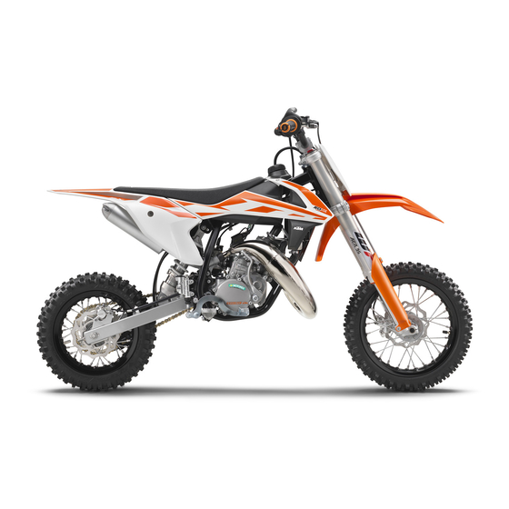
- Page 1 OWNER'S MANUAL 2017 50 SX 50 SX Mini Art. no. 3213469en...
- Page 3 KTM accepts no liability for delivery options, devi- ations from illustrations and descriptions, misprints, and other errors.
-
Page 4: Table Of Contents
TABLE OF CONTENTS 10 TUNING THE CHASSIS ..........24 TABLE OF CONTENTS MEANS OF REPRESENTATION ........4 10.1 Checking the basic chassis setting with the Symbols used ........... 4 rider's weight..........24 Formats used............ 4 10.2 Air suspension AER 35 (50 SX)......24 SAFETY ADVICE............ - Page 5 TABLE OF CONTENTS 11.36 Checking the chain, rear sprocket, engine 17 CLEANING, CARE ............84 sprocket, and chain guide ........ 52 17.1 Cleaning motorcycle ........84 11.37 Adjusting the chain guide ......54 18 STORAGE ..............85 11.38 Checking the frame ........
-
Page 6: Means Of Representation
All work marked with this symbol requires specialist knowledge and technical understanding. In the interest of the safety of your child, have these jobs performed in an authorized KTM workshop. There, your motorcycle will be optimally cared for by specially trained experts using the specialist tools required. -
Page 7: Safety Advice
SAFETY ADVICE Use definition - intended use KTM sport motorcycles are designed and built to withstand the normal stresses and strains of competitive use. The motorcycles com- ply with currently valid regulations and categories of the top international motorsport organizations. -
Page 8: Protective Clothing
Keep the Owner's Manual in an accessible place to enable you to refer to it as needed. If you would like to know more about the vehicle or have questions on the material you read, please contact an authorized KTM dealer. -
Page 9: Important Notes
Manufacturer and implied warranty The work specified in the service schedule may only be performed in an authorized KTM workshop and must be recorded in both the Service & Warranty Booklet and in KTM Dealer.net, otherwise any warranty coverage will become void. Damage or secondary damage caused by tampering with and/or conversions on the vehicle are not covered by the warranty. -
Page 10: View Of Vehicle
VIEW OF VEHICLE View of vehicle, front left (example) H01462-10 Filler cap Quick release of seat Chain guide Plug-in stand ( p. 15) Choke ( p. 14) Fuel tap ( p. 14) -
Page 11: View Of Vehicle, Rear Right (Example)
VIEW OF VEHICLE View of vehicle, rear right (example) H01463-10 Kill switch ( p. 12) Throttle grip ( p. 12) Hand brake lever ( p. 12) Chassis number ( p. 10) Kick starter ( p. 14) Foot brake lever ( p. -
Page 12: Serial Numbers
SERIAL NUMBERS Chassis number The chassis number is stamped on the right side of the steering head. 401945-10 Type label (50 SX) The type label is located on the front frame tube. 402154-10 (50 SX Mini) The type label is located on the frame at the front right. -
Page 13: Shock Absorber Article Number
SERIAL NUMBERS Shock absorber article number (50 SX) The shock absorber article number is stamped on the bottom of the shock absorber towards the rear. H01186-10 (50 SX Mini) The shock absorber article number is stamped on the top of the shock absorber towards the rear. -
Page 14: Controls
CONTROLS Hand brake lever Hand brake lever is fitted on the right side of the handlebar. The hand brake lever is used to activate the front brake. H00048-10 Throttle grip Throttle grip is fitted on the right side of the handlebar. H00048-11 Kill switch ... -
Page 15: Closing Filler Cap
CONTROLS Warning Environmental hazard Improper handling of fuel is a danger to the environment. – Do not allow fuel to enter the groundwater, the soil, or the sewage system. – Turn the tank cap counterclockwise and pull it up. V00252-10 Closing filler cap –... -
Page 16: Fuel Tap
CONTROLS Fuel tap Fuel tap is on the left of the fuel tank. Possible states Fuel tap is closed – The knurled screw is turned all the way clockwise. Fuel cannot • flow out of the fuel tank. Fuel tap is open – The knurled screw is turned all the way counterclockwise. Fuel •... -
Page 17: Foot Brake Lever
CONTROLS 6.12 Foot brake lever Foot brake lever is located in front of the right footrest. The rear brake is engaged with the foot brake lever. 401956-10 6.13 Plug-in stand The fixture for plug-in stand is located on the frame on the left side of the vehicle. The plug-in stand is used to park the motorcycle. -
Page 18: Preparing For Use
When using your motorcycle, remember that others may feel disturbed by excessive noise. – Make sure that the pre-delivery inspection work has been carried out by an authorized KTM workshop. You receive a delivery certificate and the Service and Warranty Booklet at vehicle handover. -
Page 19: Running In The Engine
PREPARING FOR USE Info Pay special attention to the safety warnings and injury risks. Explain to your child the techniques of riding and falling, e.g. how shifting weight can influence handling characteristics. – Familiarize your child with the controls. – Adjust the basic position of the hand brake lever. -
Page 20: Riding Instructions
RIDING INSTRUCTIONS Checks and maintenance measures when preparing for use Info Before each use, check the condition of the vehicle and its operating safety. The vehicle must be in perfect technical condition when it is being operated. – Check the gear oil level. ( p. -
Page 21: Starting Up
Open the throttle carefully. Riding Info If you hear unusual noises while riding, stop immediately, switch off the engine, and contact an authorized KTM workshop. – If the choke function was activated, deactivate it after the engine has warmed up. -
Page 22: Transport
RIDING INSTRUCTIONS Note Material damage The vehicle may be damaged by incorrect procedure when parking. Significant damage may be caused if the vehicle rolls away or falls over. The components for parking the vehicle are designed only for the weight of the vehicle. –... -
Page 23: Filling Up With Oil (50 Sx Mini)
RIDING INSTRUCTIONS Warning Environmental hazard Improper handling of fuel is a danger to the environment. – Do not allow fuel to enter the groundwater, the soil, or the sewage system. – Switch off the engine. – Open the filler cap. ( p. -
Page 24: Service Schedule
○ ● ● Final check: Check the vehicle for safe operation and take a test ride. ○ ● ● Make the service entry in the KTM Dealer.net and in the Service and Warranty Booklet. ○ One-time interval ● Periodic interval... -
Page 25: Recommended Work
SERVICE SCHEDULE Recommended work Annually Every 80 operating hours Every 40 operating hours Every 20 operating hours ● Change the front brake fluid. ● Change the rear brake fluid. ● ● Service the fork. ● Service the shock absorber. ● Grease the steering head bearing. -
Page 26: Tuning The Chassis
For optimal motorcycle riding characteristics and to avoid damage to forks, shock absorbers, swingarm and frame, the basic settings of the suspension components must match the rider's weight. – As delivered, KTM offroad motorcycles are adjusted for an average rider's weight (with full protective clothing). Guideline Standard rider weight 25…... -
Page 27: Adjusting The Low-Speed Compression Damping Of The Shock Absorber (50 Sx)
The shock absorber is filled with highly compressed nitrogen. – Please follow the description provided. (Your authorized KTM workshop will be glad to help.) Info The effect of the low-speed setting can be seen in slow to normal compression of the shock absorber. -
Page 28: Adjusting The Rebound Damping Of The Shock Absorber
Risk of injury Parts of the shock absorber will fly off if the shock absorber is disassembled incorrectly. The shock absorber is filled with highly compressed nitrogen. – Please follow the description provided. (Your authorized KTM workshop will be glad to help.) (50 SX) –... -
Page 29: Measuring Rear Wheel Sag Unloaded
TUNING THE CHASSIS – Position the shock absorber and rear wheel. – Mount and tighten screw and nut Guideline Screw, bottom shock 45 Nm Loctite ® 243™ absorber (33.2 lbf ft) – Remove the motorcycle from the lift stand. ( p. -
Page 30: Checking The Riding Sag Of The Shock Absorber
Risk of injury Parts of the shock absorber will fly off if the shock absorber is disassembled incorrectly. The shock absorber is filled with highly compressed nitrogen. – Please follow the description provided. (Your authorized KTM workshop will be glad to help.) Preparatory work (50 SX) –... -
Page 31: Adjusting The Riding Sag
TUNING THE CHASSIS – Tighten retaining ring (50 SX Mini) – Measure the full spring length while it is under tension and note down the value. – Loosen retaining ring – Turn adjusting ring until the spring is no longer under tension. Hook wrench (T106S) –... -
Page 32: Checking The Basic Setting Of The Fork
V00226-10 Info This is due to the volume of the hose and not due to a defect in the fork pump or the fork. Read the accompanying KTM PowerParts instructions. – Adjust the air pressure as specified. Guideline Air pressure... -
Page 33: Adjusting The Rebound Damping Of The Fork (50 Sx)
TUNING THE CHASSIS Info Never set the air pressure to a value outside the stated range. – Disconnect the fork pump from the left fork leg. When disconnecting, excess pressure will escape from the hose – the fork leg itself does not lose any air. The fork pump indicator switches off automatically after 80 seconds. -
Page 34: Adjusting The Seat Height
TUNING THE CHASSIS – Remove the screws . Take off the handlebar clamps. Remove the handlebar and 0 0 1 lay it to one side. Info 0 0 2 Protect the motorcycle and its attachments from damage by covering them. Do not bend the cables and lines. - Page 35 TUNING THE CHASSIS – Mount nut and tighten fitting. Guideline Screw, top shock absorber 45 Nm Loctite ® 243™ (33.2 lbf ft) V00264-10 Finishing work – Remove the motorcycle from the lift stand. ( p. 34)
-
Page 36: Service Work On The Chassis
SERVICE WORK ON THE CHASSIS 11.1 Raising the motorcycle with a lift stand Note Danger of damage The parked vehicle can roll away or fall over. – Park the vehicle on a firm and level surface. – Raise the motorcycle at the frame underneath the engine. Lift stand (78929955100) Neither wheel is in contact with the ground. -
Page 37: Cleaning The Dust Boots Of The Fork Legs
SERVICE WORK ON THE CHASSIS 11.4 Cleaning the dust boots of the fork legs Preparatory work – Raise the motorcycle with a lift stand. ( p. 34) – Remove the fork protector. ( p. 35) Main work – Push dust boots of both fork legs downward. -
Page 38: Removing The Fork Legs
SERVICE WORK ON THE CHASSIS – Position the fork protector on the left fork leg. Mount and tighten screws Guideline Remaining screws, chassis 10 Nm (7.4 lbf ft) – Position the brake line and clamp. Mount and tighten screws V00266-11 11.7 Removing the fork legs... -
Page 39: Removing The Lower Triple Clamp
SERVICE WORK ON THE CHASSIS – Tighten screws Guideline Screw, top triple clamp 20 Nm (14.8 lbf ft) – Tighten screws Guideline Screw, bottom triple clamp 15 Nm (11.1 lbf ft) V00269-11 (50 SX Mini) – Position the fork legs. ... -
Page 40: Installing The Lower Triple Clamp
SERVICE WORK ON THE CHASSIS – Remove protective ring – Remove the lower triple clamp with the steering stem. – Take out the upper steering head bearing. V00273-10 11.10 Installing the lower triple clamp Main work – Clean the bearing and sealing elements, check for damage, and grease. High viscosity grease ( p. - Page 41 SERVICE WORK ON THE CHASSIS – Tighten nut Guideline – Nut, steering head M20x1.5 10 Nm (7.4 lbf ft) Nut, steering head M20x1.5 9 Nm Only applies (6.6 lbf ft) when using: Holding wrench for steering head bearing V00275-10 (45229050000) –...
-
Page 42: Checking Play Of Steering Head Bearing
Danger of accidents Incorrect steering head bearing play impairs the handling characteristic and damages components. – Correct incorrect steering head bearing play immediately. (Your authorized KTM workshop will be glad to help.) Info If the bike is ridden with play in the steering head bearing, the bearing and the bearing seats in the frame can become dam- aged over time. -
Page 43: Adjusting The Steering Head Bearing Play
SERVICE WORK ON THE CHASSIS 11.12 Adjusting the steering head bearing play Preparatory work – Raise the motorcycle with a lift stand. ( p. 34) Main work (50 SX) – Pull fuel tank breather out of the steering stem. –... -
Page 44: Greasing The Steering Head Bearing
SERVICE WORK ON THE CHASSIS 11.13 Greasing the steering head bearing – Remove the lower triple clamp. p. 37) – Install the lower triple clamp. p. 38) 400563-01 11.14 Removing the fuel tank Danger Fire hazard Fuel is highly flammable. The fuel in the fuel tank expands when warm and can escape if overfilled. –... -
Page 45: Installing The Fuel Tank
SERVICE WORK ON THE CHASSIS 11.15 Installing the fuel tank Danger Fire hazard Fuel is highly flammable. The fuel in the fuel tank expands when warm and can escape if overfilled. – Do not refuel the vehicle in the vicinity of open flames or lit cigarettes. –... -
Page 46: Installing The Start Number Plate
SERVICE WORK ON THE CHASSIS 11.17 Installing the start number plate – Attach the start number plate to the brake line. – Position the start number plate. Holding lugs engage in the fender. H01426-10 – Mount and tighten screw Guideline Screw, start number plate 4 Nm (3 lbf ft) -
Page 47: Removing The Shock Absorber
SERVICE WORK ON THE CHASSIS 11.20 Removing the shock absorber Preparatory work (50 SX) – Raise the motorcycle with a lift stand. ( p. 34) (50 SX Mini) – Raise the motorcycle with a lift stand. ( p. 34) – Remove the rear wheel. -
Page 48: Removing The Seat
SERVICE WORK ON THE CHASSIS Main work (50 SX) – Push splash protector to the side. – Position the shock absorber with screw , depending on the desired seating height. – Raise the swingarm; position the shock absorber with screw H01430-11 –... -
Page 49: Mounting The Seat
SERVICE WORK ON THE CHASSIS 11.23 Mounting the seat – Hook the seat onto screw , lower the seat at the rear, and push it forward. Catch hooks into the fuel tank. H01431-10 – Close quick release H00066-11 11.24 Removing the air filter... -
Page 50: Cleaning The Air Filter And Air Filter Box
SERVICE WORK ON THE CHASSIS 11.26 Cleaning the air filter and air filter box Warning Environmental hazard Hazardous substances cause environmental damage. – Dispose of oils, grease, filters, fuel, cleaning agents, brake fluid, etc., correctly and in compliance with the applicable regu- lations. -
Page 51: Changing The Glass Fiber Yarn Filling Of The Main Silencer
SERVICE WORK ON THE CHASSIS 11.29 Changing the glass fiber yarn filling of the main silencer Warning Danger of burns The exhaust system gets very hot when the vehicle is driven. – Allow the exhaust system to cool down before performing any work on the vehicle. Info Over time, the fibers of the glass fiber yarn escape and the damper "burns"... -
Page 52: Installing The Engine Sprocket Cover
SERVICE WORK ON THE CHASSIS 11.31 Installing the engine sprocket cover Main work (50 SX) – Position the engine sprocket cover. Mount screws but do not tighten yet. – Mount and tighten screw Guideline Screw, engine sprocket cover 12 Nm (8.9 lbf ft) –... -
Page 53: Checking The Chain Tension
SERVICE WORK ON THE CHASSIS Preparatory work – Raise the motorcycle with a lift stand. ( p. 34) Main work – Clean the chain regularly and then treat with chain spray. Chain cleaner ( p. 95) Off-road chain spray ( p. -
Page 54: Adjusting The Chain Tension
SERVICE WORK ON THE CHASSIS 11.35 Adjusting the chain tension Warning Danger of accidents Incorrect chain tension damages components and results in accidents. If the chain is tensioned too much, the chain, engine sprocket, rear sprocket, transmission and rear wheel bearings wear more quickly. - Page 55 SERVICE WORK ON THE CHASSIS Info When a new chain is mounted, the rear sprocket and engine sprocket should also be changed. New chains wear out faster on old, worn sprockets. – Check the chain sliding guard for wear. » If the ridge is worn down to the level of the main corpus: –...
-
Page 56: Adjusting The Chain Guide
If the frame exhibits cracks or deformation due to a mechanical impact: – Change the frame. Info Always replace a frame that has been damaged due to a mechanical impact. Repair of the frame is not authorized by KTM. S00876-01 11.39 Checking the swingarm –... -
Page 57: Checking The Throttle Cable Routing
SERVICE WORK ON THE CHASSIS 11.40 Checking the throttle cable routing Warning Danger of accidents The throttle cable may slip out of the guide if routed incorrectly. The throttle slide will then no longer be closed and the speed can no longer be controlled. –... -
Page 58: Brake System
BRAKE SYSTEM 12.1 Checking play of handbrake lever – Push the handbrake lever forwards and check the play Play of hand brake lever 3… 5 mm (0.12… 0.2 in) » If the play does not meet specifications: – Adjust the play of the hand brake lever. ( p. -
Page 59: Checking Brake Discs
If the brake fluid level drops below the specified marking or the specified value, the brake system is leaking or the brake lin- ings are worn down. – Check the brake system and do not continue riding until the problem is eliminated. (Your authorized KTM workshop will be glad to help.) Warning Skin irritation Brake fluid causes skin irritation. -
Page 60: Adding Front Brake Fluid
If the brake fluid level drops below the specified marking or the specified value, the brake system is leaking or the brake lin- ings are worn down. – Check the brake system and do not continue riding until the problem is eliminated. (Your authorized KTM workshop will be glad to help.) Warning Skin irritation Brake fluid causes skin irritation. -
Page 61: Checking The Front Brake Linings
Danger of accidents Brake linings which have not been approved alter the braking efficiency. Not all brake linings are tested and approved for KTM motorcycles. The structure and friction coefficient of the brake linings, and thus their brake power, may vary greatly from that of original brake linings. - Page 62 BRAKE SYSTEM Warning Environmental hazard Hazardous substances cause environmental damage. – Dispose of oils, grease, filters, fuel, cleaning agents, brake fluid, etc., correctly and in compliance with the applicable regu- lations. Info Never use DOT 5 brake fluid. It is silicone-based and purple in color. Oil seals and brake lines are not designed for DOT 5 brake fluid.
-
Page 63: Checking The Free Travel Of The Foot Brake Lever
BRAKE SYSTEM – Check the wheel bearing for damage and wear. » If the wheel bearing is damaged or worn: – Change the front wheel bearing. – Clean and grease the contact surfaces of the spacers. Long-life grease ( p. -
Page 64: Adjusting The Free Travel Of The Foot Brake Lever
BRAKE SYSTEM – Disconnect spring – Move the foot brake lever back and forth between the end stop and the foot brake cylinder piston bracket and check free travel Guideline Free travel of foot brake lever 3… 5 mm (0.12… 0.2 in) »... -
Page 65: Checking Rear Brake Fluid Level
If the brake fluid level drops below the MIN marking, the brake system is leaking or the brake linings are worn down. – Check the brake system and do not continue riding until the problem is eliminated. (Your authorized KTM workshop will be glad to help.) Warning Danger of accidents Old brake fluid reduces the braking effect. -
Page 66: Checking The Rear Brake Linings
Changing the rear brake linings Warning Danger of accidents Incorrect maintenance will cause the brake system to fail. – Ensure that service work and repairs are performed professionally. (Your authorized KTM workshop will be glad to help.) Warning Skin irritation Brake fluid causes skin irritation. –... - Page 67 Danger of accidents Brake linings which have not been approved alter the braking efficiency. Not all brake linings are tested and approved for KTM motorcycles. The structure and friction coefficient of the brake linings, and thus their brake power, may vary greatly from that of original brake linings.
- Page 68 BRAKE SYSTEM – Insert the new brake linings. Info Always change the brake linings in pairs. Ensure that the brake linings are correctly positioned in the holding spring. – Position the brake caliper on the brake disc. The brake linings are correctly positioned. –...
-
Page 69: Wheels, Tires
WHEELS, TIRES 13.1 Removing the front wheel Preparatory work – Raise the motorcycle with a lift stand. ( p. 34) Main work – Remove screw – Loosen screws H01451-10 Warning Danger of accidents Damaged brake discs reduce the braking effect. –... -
Page 70: Removing The Rear Wheel
WHEELS, TIRES – Mount and tighten screw Guideline Screw, front wheel spindle 40 Nm Loctite ® 243™ (29.5 lbf ft) – Operate the hand brake lever several times until the brake linings are seated cor- rectly against the brake disc. –... -
Page 71: Checking The Tire Condition
Checking the tire condition Info Only mount tires approved and/or recommended by KTM. Other tires could have a negative effect on handling characteristics. The type, condition, and air pressure of the tires all have a major impact on the handling of the motorcycle. -
Page 72: Checking Tire Air Pressure
Other spokes will become looser as a result. – Check spoke tension regularly, and in particular on a new vehicle. (Your authorized KTM workshop will be glad to help.) Info A loose spoke can cause wheel imbalance, which leads to more loose spokes in a short time. -
Page 73: Cooling System
COOLING SYSTEM 14.1 Cooling system The water pump in the engine forces the coolant to flow. The pressure resulting from the warming of the cooling system is regulated by a valve in the radiator cap . This ensures that operating the vehicle at the specified coolant temperature will not result in a risk of malfunctions. -
Page 74: Checking The Coolant Level
COOLING SYSTEM 14.3 Checking the coolant level Warning Danger of scalding During motorcycle operation, the coolant gets very hot and is under pressure. – Do not open the radiator, the radiator hoses or other cooling system components if the engine or the cooling system are at operating temperature. -
Page 75: Refilling With Coolant
COOLING SYSTEM – Position the motorcycle upright. – Place a suitable container under the water pump cover. – Remove screw . Remove the radiator cap. – Completely drain the coolant. – Mount and tighten screw with a new seal ring. Guideline Drain plug, water pump cover 6 Nm (4.4 lbf ft) -
Page 76: Tuning The Engine
TUNING THE ENGINE 15.1 Checking the installation position of the throttle grip – Position the throttle grip so that adjustment angle is reached. Guideline 35° Adjustment angle , throttle grip Info If the throttle grip is turned too far forward, the throttle cable will slip out of the guide on the carburetor. -
Page 77: Carburetor - Idle (50 Sx)
TUNING THE ENGINE – Turn adjusting screw so that there is throttle cable play at the throttle grip. Guideline Play in gas throttle cable 3… 5 mm (0.12… 0.2 in) – Tighten nut – Slide on sleeve 400192-11 Finishing work –... -
Page 78: Carburetor - Adjusting Idle Speed
TUNING THE ENGINE Guideline Choke function deactivated – Choke knob is in lower position. The O-ring is not visible. ( p. 14) Idle speed 1,400… 1,500 rpm – Turn the idle adjusting screw slowly clockwise until the idle speed begins to fall. -
Page 79: Checking The Clutch Setting
TUNING THE ENGINE Info If the engine speed rises considerably, reduce the idle speed to a normal level and repeat the above steps. If the procedure described here does not lead to satisfactory results, the cause may be a wrongly dimensioned idling jet. If you can turn the idle air adjusting screw to the end without any change of engine speed, you need to install a smaller idling jet. -
Page 80: Adjusting The Clutch
TUNING THE ENGINE – Lay the vehicle down on its left side as shown. H01456-01 – Remove screws – Remove clutch cover with the seal ring. H01458-10 15.10 Adjusting the clutch Preparatory work – Remove the clutch cover. p. -
Page 81: Installing The Clutch Cover
TUNING THE ENGINE Finishing work – Install the clutch cover. p. 79) – Check the gear oil level. ( p. 81) – Check the clutch setting. p. 77) 15.11 Installing the clutch cover Main work – Position clutch cover with the seal ring. -
Page 82: Service Work On The Engine
SERVICE WORK ON THE ENGINE 16.1 Checking oil level (50 SX Mini) Preparatory work – Stand the motorcycle upright on a horizontal surface. Main work – Check the oil level in the oil tank. For a full fuel tank, the oil tank must be filled up toMIN mark ... -
Page 83: Checking The Gear Oil Level
SERVICE WORK ON THE ENGINE – Turn oil pump gear counterclockwise until oil flows out of oil line without bubbles. V00276-10 – Connect oil line – Position the oil pump. – Mount and tighten screws Guideline Screw, oil pump 6 Nm (4.4 lbf ft) 300651-10... -
Page 84: Adding Gear Oil
SERVICE WORK ON THE ENGINE Info Drain gear oil with engine at operating temperature. Preparatory work – Stand the motorcycle on the plug-in stand on a horizontal surface. Main work (50 SX) – Place a suitable container under the engine. –... - Page 85 SERVICE WORK ON THE ENGINE (50 SX) – Remove gear oil monitoring screw H00083-10 (50 SX Mini) – Remove gear oil monitoring screw S00882-10 – Remove filler plug . Position the motorcycle upright. – Add gear oil until it flows out of the hole in the gear oil monitoring screw. Gear oil (ATF Dexron 3) ( p.
-
Page 86: Cleaning, Care
CLEANING, CARE 17.1 Cleaning motorcycle Note Material damage Components become damaged or destroyed if a pressure cleaner is used incorrectly. The high pressure forces water into the electrical components, connectors, throttle cables, and bearings, etc. Pressure which is too high causes malfunctions and destroys components. –... -
Page 87: Storage
70) – Store the vehicle in a dry location that is not subject to large fluctuations in tem- perature. Info KTM recommends jacking up the motorcycle. – Raise the motorcycle with a lift stand. ( p. 34) – Cover the vehicle with a tarp or similar cover that is permeable to air. -
Page 88: Troubleshooting
TROUBLESHOOTING Faults Possible cause Action – Engine turns but does not start Operating error Carry out the start procedure. ( p. 18) – Motorcycle was out of use for a long Empty the carburetor float chamber. time and there is old fuel in the float chamber –... - Page 89 TROUBLESHOOTING Faults Possible cause Action – Engine has too little power Exhaust system leaky, deformed or Check exhaust system for damage. too little glass fiber yarn filling in – Change the glass fiber yarn filling of the main main silencer silencer.
-
Page 90: Technical Data
TECHNICAL DATA 20.1 Engine Design 1-cylinder 2-stroke engine, water-cooled, with reed intake Displacement 49.0 cm³ (2.99 cu in) Stroke 40 mm (1.57 in) Bore 39.5 mm (1.555 in) Crankshaft bearing 2 grooved ball bearings Conrod bearing Needle bearing Piston pin bearing Needle bearing Pistons Aluminum cast... -
Page 91: Carburetor With Carburetor Tuning
TECHNICAL DATA 20.3 Carburetor with carburetor tuning 20.3.1 50 SX Carburetor type Dell`Orto PHBG 19BS Needle position 2nd position from top Idle mixture adjusting screw Open 3 turns Main jet Jet needle Idling jet Needle jet 262AU Throttle slide Cold start jet 20.3.2 50 SX Mini Carburetor type... -
Page 92: Tires
(50 SX Mini) 2.50 - 10 33J TT 2.75 - 10 38J TT MAXXIS MAXX CROSS SI MAXXIS MAXX CROSS SI Additional information is available in the Service section under: http://www.ktm.com 20.7 Fork 20.7.1 50 SX Fork part number 07.18.6Q.02... -
Page 93: Sx Mini
TECHNICAL DATA Grease capacity, left cartridge 6 ml (0.2 fl. oz.) Multi-purpose grease (00062010051) ( p. 93) 20.7.2 50 SX Mini Fork part number 07.18.1Q.01 WP Performance Systems USD 35 Fork Fork length 580 mm (22.83 in) Spring rate Weight of rider: 15… 25 kg (33… 55 lb.) 1.8 N/mm (10.3 lb/in) Weight of rider (standard): 25…... -
Page 94: Chassis Tightening Torques
TECHNICAL DATA Spring rate Weight of rider: 15… 25 kg (33… 55 lb.) 65 N/mm (371 lb/in) Weight of rider (standard): 25… 35 kg (55… 77 lb.) 75 N/mm (428 lb/in) Weight of rider: 35… 45 kg (77… 99 lb.) 85 N/mm (485 lb/in) Spring length 120 mm (4.72 in) -
Page 95: Substances
SUBSTANCES Brake fluid DOT 4 / DOT 5.1 Standard/classification – Guideline – Use only brake fluid that complies with the specified standard (see specifications on the container) and that exhibits the corre- sponding properties. Recommended supplier Castrol – RESPONSE BRAKE FLUID SUPER DOT 4 Motorex ®... - Page 96 SUBSTANCES Shock absorber fluid (SAE 2.5) (50180751S1) Standard/classification – SAE ( p. 97) (SAE 2.5) Guideline – Use only oils that comply with the specified standards (see specifications on the container) and that exhibit the corresponding properties. Super unleaded (ROZ 95/RON 95/PON 91) Standard/classification –...
-
Page 97: Auxiliary Substances
Motorex ® – Chain Clean Fuel additive Recommended supplier Motorex ® – Fuel Stabilizer Grip adhesive (00062030051) Recommended supplier KTM AG – GRIP GLUE High viscosity grease Recommended supplier ® – LGHB 2 Long-life grease Recommended supplier Motorex ® –... - Page 98 AUXILIARY SUBSTANCES Universal oil spray Recommended supplier Motorex ® – Joker 440 Synthetic...
-
Page 99: Standards
STANDARDS JASO FD JASO FD is a classification for a 2-stroke engine oil that was specifically developed for the extreme demands of racing. Thanks to first rate synthetic esters and specially designed additives, superb combustion is achieved even under extreme operating conditions. The SAE viscosity classes were defined by the Society of Automotive Engineers and are used for classifying oils according to their vis- cosity. -
Page 100: List Of Abbreviations
LIST OF ABBREVIATIONS Art. no. Article number circa compare e.g. for example etc. et cetera i.a. inter alia number poss. possibly... -
Page 101: Index
INDEX Compression damping, high-speed INDEX shock absorber, adjusting ..... 25 Accessories ........7 Compression damping, low-speed shock absorber, adjusting . - Page 102 INDEX removing ....... . . 42 Protective clothing ......6 Fuel tap .
- Page 103 INDEX engine tightening torques ..... 88 fork ........90 shock absorber .
- Page 104 *3213469en* 3213469en 04/2016 KTM Sportmotorcycle GmbH 5230 Mattighofen/Austria Photo: Mitterbauer/KTM http://www.ktm.com...
Need help?
Do you have a question about the 50 SX 2017 and is the answer not in the manual?
Questions and answers