Table of Contents
Advertisement
Advertisement
Table of Contents

Related Manuals for Control Techniques Commander SE SE11200025


Summary of Contents for Control Techniques Commander SE SE11200025
- Page 1 DATASHEET CONTROL TECHNIQUES SE23400150 OTHER SYMBOLS: RGB ELEKTRONIKA AGACIAK CIACIEK SPÓŁKA JAWNA Jana Dlugosza 2-6 Street 51-162 Wrocław www.rgbelektronika.pl Poland biuro@rgbelektronika.pl +48 71 325 15 05 www.rgbautomatyka.pl www.rgbautomatyka.pl www.rgbelektronika.pl...
- Page 2 YOUR PARTNER IN MAINTENANCE Repair this product with RGB ELEKTRONIKA ORDER A DIAGNOSIS LINEAR ENCODERS SYSTEMS INDUSTRIAL COMPUTERS ENCODERS CONTROLS SERVO AMPLIFIERS MOTORS MACHINES OUR SERVICES POWER SUPPLIERS OPERATOR SERVO PANELS DRIVERS At our premises in Wrocław, we have a fully equipped servicing facility. Here we perform all the repair works and test each later sold unit.
-
Page 3: User Guide
User Guide Commander SE Sizes 1 to 5 Variable speed drive for 3 phase induction motors from 0.25kW to 37kW Part Number: 0452-0061 Issue Number: 8 www.controltechniques.com... - Page 4 SE Drives, there may be some differences between their software and the software in this product. These differences may cause this product to function dif- ferently. This may also apply to Drives returned from a Control Techniques Service Centre.
-
Page 5: Table Of Contents
Contents Safety Information Warnings, Cautions and notes Electrical safety - general warning System design and safety of personnel Environmental limits Compliance with regulations Motor Adjusting parameters Options Technical Data Power dependant rating data General data RFI Filters Installing the drive Safety information Planning the installation Mechanical installation... - Page 6 Parameter List Advanced Functions 10.1 Speed control 10.2 Ramps 10.3 Torque control 10.4 Stopping 10.5 Programmable I/O 10.6 Motor protection 10.7 Monitoring 10.8 Auxiliary functions 10.9 Second motor selection UL Listing Information 11.1 Common UL information 11.2 Power dependant UL information Commander SE User Guide Issue Number 8...
-
Page 7: Declaration Of Conformity
Declaration of Conformity Control Techniques, The Gro, Newtown, Powys, UK. SY16 3BE SE11200025 SE11200037 SE11200055 SE11200075 SE2D200075 SE2D200110 SE2D200150 SE2D200220 SE23200400 SE23400075 SE23400110 SE23400150 SE23400220 SE23400300 SE23400400 SE33200550 SE33400550 SE33200750 SE33400750 SE43401100 SE43401500 SE43401850 SE53402200 SE53403000 SE53403700 The AC variable speed drive products listed above, have been designed and manufactured in... -
Page 8: Safety Information
Safety Information Warnings, Cautions and notes Warning contains information which is essential for avoiding a safety hazard. WARNING Caution contains information which is necessary for avoiding a risk of damage to the product or other equipment. CAUTION Note contains information which helps to ensure correct operation of the product. NOTE Electrical safety - general warning The voltages used in the drive can cause severe electrical shock and/or burns, and... -
Page 9: Environmental Limits
Environmental limits Instructions in this User Guide regarding transport, storage, installation and use of the drive must be complied with, including the specified environmental limits. Drives must not be subjected to excessive physical force. Compliance with regulations The installer is responsible for complying with all relevant regulations, such as national wiring regulations, accident prevention regulations and electromagnetic compatibility (EMC) regulations. -
Page 10: Options
Options The following options are available for Commander SE; • Quickey for rapid parameter transfer (SE55) • Standard and low earth leakage footprint / side mounting RFI filters and low cost panel mounting RFI filters • Universal Keypad, IP65, hand held or door mounting plain text, LCD display ™... -
Page 11: Technical Data
Technical Data Power dependant rating data Model code explanation SE 1 1 2 xxxxx Drive kilowatt rating: 00025 = 0.25kW etc. Drive voltage rating: 2 = 230V, 4 = 400V Number of input phases: 1 = 1∅, 3 = 3∅, D = 1∅ and 3∅ Frame size. - Page 12 MODEL SE2D200... AC supply voltage and frequency Single or 3 phase 200 to 240V +/- 10%, 48 to 62Hz Input displacement factor (cos φ) >0.97 Nominal motor power - kW 0.75 Nominal motor power - hp Output voltage and frequency 3 phase, 0 to input voltage, 0 to 1000Hz 100% RMS output current - A 10.0...
- Page 13 MODEL SE23200400 AC supply voltage and frequency 3 phase 200 to 240V +/- 10%, 48 to 62Hz Input displacement factor (cos φ) >0.97 Nominal motor power - kW Nominal motor power - hp Output voltage and frequency 3 phase, 0 to input voltage, 0 to 1000Hz 100% RMS output current - A 17.0 150% overload current for 60 secs - A...
- Page 14 MODEL SE23400... AC supply voltage and frequency 3 phase 380 to 480V +/- 10%, 48 to 62Hz Input displacement factor (cos φ) >0.97 Nominal motor power - kW 0.75 Nominal motor power - hp Output voltage and frequency 3 phase, 0 to input voltage, 0 to 1000Hz 100% RMS output current - A 150% overload current for 60 secs - A 11.4...
- Page 15 MODEL SE33200... AC supply voltage and frequency 3 phase 200 to 240V +/-10%, 48 to 62Hz Input displacement factor (cos φ) >0.97 Nominal motor power - kW Nominal motor power - hp 10.0 Output voltage and frequency 3 phase, 0 to input voltage, 0 to 1000Hz 100% RMS output current - A 25.0 28.5...
- Page 16 MODEL SE33400... AC supply voltage and frequency 3 phase 380 to 480V +/-10%, 48 to 62Hz Input displacement factor (cos φ) >0.97 Nominal motor power - kW Nominal motor power - hp 10.0 Output voltage and frequency 3 phase, 0 to input voltage, 0 to 1000Hz 100% RMS output current - A 13.0 16.5...
- Page 17 MODEL SE4340... 1100 1500 1850 AC supply voltage and frequency 3 phase 380 to 480V +/-10%, 48 to 62Hz Input displacement factor (cosφ) >0.97 Nominal motor power - kW 18.5 Nominal motor power - hp Output voltage and frequency 3 phase, 0 to input voltage, 0 to 1000Hz 100% RMS output current - A 24.5 30.5...
- Page 18 MODEL SE5340... 2200 3000 3700 AC supply voltage and frequency Three phase 380 - 480V +/- 10% 48 - 62Hz Input displacement factor (cos φ) >0.97 Nominal motor power - kW Nominal motor power - hp Output voltage and frequency 3 phase, 0 to input voltage, 0 to 1000Hz 100% RMS output current - A 150% overload current for 60 secs - A...
-
Page 19: General Data
Braking Resistors - High Temperatures Braking resistors can reach high temperatures. Locate braking resistors so that damage cannot result. Use cable having insulation capable of withstanding high WARNING temperatures. Braking Resistors - Overload Protection It is essential that an overload protection device is incorporated in the braking resistor circuit. - Page 20 If the drive is not mounted as indicated, hazardous live parts will be exposed and the IP Rating or NEMA 1 enclosure rating of the drive will be invalid. WARNING Input phase Phase imbalance not to exceed 2% negative phase sequence imbalance: Ambient -10°C to +40°C (14°F to 104°F) at 6kHz switching frequency.
-
Page 21: Rfi Filters
Serial 2-wire EIA485 via RJ45 connector Communications: ANSI and Modbus RTU protocols supported Switching 3, 6, and 12 kHz are available with Intelligent Thermal Frequencies: Management software automatically changing the switching frequencies depending on load conditions, heatsink temperature and output frequency, to prevent heatsink overtemperature trips. - Page 22 Used with Filter Part Filter Type Mounting Max motor cable length Standard Low leakage Low cost Footprint Side 4200-6203 SE23200400 4200-6303 4200-6209 Table 3.28 Commander SE Size 2 - 200V, 26A, 3 phase Used with Filter Part Filter Type Mounting Max motor cable length Standard...
-
Page 23: Installing The Drive
Installing the drive Safety information Follow the instructions The mechanical and electrical installation instructions must be adhered to. Any questions or doubt should be referred to the supplier of the equipment. It is the WARNING responsibility of the owner or user to ensure that the installation of the drive and any external option unit, and the way in which they are operated and maintained, comply with the requirements of the Health and Safety at Work Act in the United Kingdom or applicable legislation and regulations and codes of practice in the... -
Page 24: Mechanical Installation
equipment. If it is necessary to meet strict emission limits, or if it is known that electromagnetically sensitive equipment is located nearby, then full precautions must be observed. These will include the use of RFI filters at the drive inputs, which must be located very close to the drives. - Page 25 Back-plate 45mm 1.772in 346mm 335mm 368mm 13.622in 13.189in 14.488in 175mm 6.890in 187.5mm 16.5mm 16.5mm 7.382in 260mm 0.650in 0.650in 375mm 10.236in 14.764in Figure 4.2 Surface mounting Size 5 units The drive should be mounted vertically. A mounting template is provided on the NOTE drive packing carton to aid installation.
- Page 26 Through-hole mounting Surface mounting bracket bracket Table 4.1 Size 5 Mounting brackets 102mm 195.5mm 4.016in 7.697in 244mm 9.606in 90mm 130mm = 7mm 3.583in 5.118in 0.276in 350mm 13.780in Figure 4.4 Size 5 baffle plate When a Commander SE size 5 is through-panel mounted a baffle plate is required to ensure the correct level of air flow is maintained through the heatsink.
- Page 27 4.3.2 Commander SE standard and low earth leakage Footprint/ Side mounting RFI Filter: Size 1 and 2 8 x M4 holes Size 3 and 4 8 x M5 holes for footprint mounting Cable length Earth stud: SE Size 1 - M4 SE Size 2 ~ 4 - M5 Figure 4.5 RFI filter dimensions Drive...
- Page 28 4.3.4 Commander SE Size 2 and 3 Low cost single and three phase RFI Filter mounting dimensions, 4200-6204 and 4200-6304. ∅ Cable length 4200-6204 = 250mm 4200-6304 = 300mm Figure 4.7 RFI filter dimensions ∅ Z 98.5 3 85.5 57.6 2 4.3 x 7.5 4.3.5 Commander SE Size 2, 3 and 4 Low cost three phase RFI Filter mounting...
- Page 29 4.3.6 SE53402200 bookcase mounted filter, 4200-6116 Figure 4.9 RFI filter dimensions 4.3.7 SE53403000 ~ SE53403700 bookcase mounted filter, 4200-6117, 4200-6106 4200-6117 = M6 4200-6106 = M8 Figure 4.10 RFI filter dimensions ∅ Z 4200-6116 337 13.27 259.5 10.22 3.54 100 3.94 275 10.83 1.97 290 11.42 0.28...
-
Page 30: Electrical Installation
If the drive has failed in a manner that causes the display to go blank immediately, it is possible the capacitors will not be discharged. In this case, consult Control Techniques or their authorised distributor. Commander SE User Guide www.controltechniques.com... - Page 31 AC supply by plug and socket Special attention must be given if the drive is installed in equipment which is connected to the AC supply by a plug and socket. The AC supply terminals of the WARNING drive are connected to the internal capacitors through rectifier diodes which are not intended to give safety isolation.
- Page 32 The ground loop impedance must conform to the requirements of local safety regulations. The ground connections must be inspected and tested at appropriate intervals. WARNING Earth and ground leakage Sizes 1 ~ 4 The drive has a very small leakage current between the power lines and ground, which is of no consequence.
- Page 33 an insulating jacket tend to have high capacitance. If a high capacitance cable is used, the maximum cable lengths in Table 4.2 should be halved. For further information please refer to the Commander SE Advanced User Guide. Multiple Motors For advice on multiple motor applications where a number of small motors are connected to the output of one drive, please refer to the Commander SE Advanced User Guide.
-
Page 34: Electromagnetic Compatibility (Emc)
Commander SE sizes 3, 4 and 5 drives include DC chokes, AC reactors are only NOTE required for harmonic reduction. *These input reactors are not stocked by Control Techniques. Therefore they NOTE should be ordered directly from the manufacturer, Skot Transformers, or sourced locally. - Page 35 Figure 4.7 shows the requirements which be followed closely in order to meet EMC emission standards. Further guidance and information on EMC standards is given in the EMC Data sheets which are available from Control Techniques’ Drive Centres or Distributors.
- Page 36 Control Techniques’ Drive Centres and Distributors. 4.5.3 Special requirements Special considerations are required for the following requirements: Meeting the residential emission standard, EN50081-1 (Size 1 only) One of the footprint filters (part number 4200-6102 or 4200-6103) must be used.
- Page 37 High ground leakage current Most RFI filters have ground leakage current exceeding 3.5mA. All equipment using these filters must be provided with a permanent fixed ground connection. WARNING Special low-leakage filters are provided for applications where a permanent ground connection is not practical. Commander SE Size 1 Filter and Switching Frequency Motor cable...
- Page 38 Motor cable Filter and Switching Frequency length Standard Low Cost Low Leakage (4200-6203) (4200-6303) (4200-6209) 3kHz 6kHz 12kHz 3kHz 6kHz 12kHz 3kHz 6kHz 12kHz Table 4.8 Drive Range: SE23200400, three phase Commander SE Size 3 Filter and Switching Frequency Motor cable length Standard Low Cost...
- Page 39 Commander SE Size 5 Motor cable Filter and Switching Frequency length 4200-6116* 4200-6117** 4200-6106*** 3kHz 6kHz 12kHz 3kHz 6kHz 12kHz 3kHz 6kHz 12kHz Table 4.13 Drive range SE53402200 ~ SE53403700 Filter used on drive range SE53402200 Filter used on SE53403000 *** Filter used on SE53403700 Key: EN50081-1 Conducted emission requirements of the generic emission standard for...
- Page 40 Maximum IP Rating Weight Operational Worst Case Terminal Part Number Power Leakage Leakage Torques Losses Current Current Nm / lb ft 4200-6401 26.1 29.4 2.2 / 1.6 4200-6402 11.7 14.1 2.2 / 1.6 4200-6403 2.2 / 1.6 4200-6404 24.5 2.2 / 1.6 Table 4.17 Commander SE Size 4 Maximum IP Rating...
-
Page 41: Terminals
Terminals Power terminal connections L2/N Optional RFI filter Motor Ground Optional line reactor Fuses Circuit breaker /Isolator Motor L2/N Mains Supply * See Fuses on page 24 Supply Ground Figure 5.1 Commander SE Size 1 power terminal connections Braking Optional RFI Resistor filter Motor... -
Page 42: Control Terminal Connections
Optional RFI Optional filter Braking Optional Resistor line reactor Thermal Fuses protection device Stop Start/ Motor Reset Mains Supply Motor Supply Ground Ground Figure 5.3 Commander SE Size 5 power terminal connections 5.1.1 Thermal protection for an optional braking resistor Figure 5.2 shows a typical circuit arrangement for braking resistor protection. -
Page 43: Serial Communication Connections
The connection arrangement shown here illustrates how the terminals are NOTE intended to be used. Screening of the analog signal wires is not essential, but reduces the risk of electrical noise causing disturbance to the signals. Where full EMC precautions are required, the guidelines in section 4.5.2 must also be followed to ensure compliance with radio frequency emission limits. -
Page 44: Control Terminal Specifications
Control terminal specifications Isolation of control circuits The control terminals of the Commander SE drive are double-insulated from the power electronics and single-insulated from the status relay contacts. Providing WARNING that the voltage on the status relay contacts does not exceed 110V, the control terminals meet the requirements for SELV in EN50178. - Page 45 The remote current speed-reference input circuit incorporates a protection circuit to prevent any internal damage within the drive in the event of an external controller fault. This protection circuit senses the input current and if this exceeds 25mA, a FET disconnects the external controller from the drive.
- Page 46 * Following a drive trip and a reset via the Stop/Reset key the Run Forward or Run Reverse terminals will need to be opened and closed to allow the drive to run. This ensures that the drive does not start when the Stop/Reset key is pressed. +24V output ±...
-
Page 47: Handling And Programming
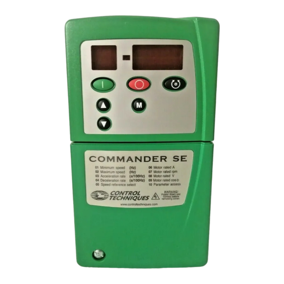
Handling and Programming Display and keypad The display and keypad are used for the following: • Displaying the operating status of the drive • Displaying fault or trip codes • Reading and changing parameter values • Stopping, starting and resetting the drive Sign LED Display Control Keys... -
Page 48: Display Messages
Display Messages 6.2.1 Status mode In status mode, left hand display indicates a two letter mnemonic indicating the status of the drive: Display Status Explanation The drive is enabled and ready for a start command. Drive ready The output bridge is inactive. The output bridge is inactive because the drive is Drive inhibited disabled, or a coast to stop is in progress, or the... -
Page 49: Saving Parameters
STATUS MODE Press Press Hold 4 mins timeout 2 secs PARAMETER VIEW MODE Select parameter to change Press Parameter number flashing PARAMETER EDIT MODE Change parameter value Press Parameter value flashing Figure 6.2 Selecting and changing parameters Saving parameters Parameters are automatically saved when the mode button is pressed when going from parameter edit mode to parameter view mode. -
Page 50: Unlocking A Security Code
Unlocking a security code 1. Select a parameter to be edited 2. Press the MODE key. The right hand display will flash CodE CodE 3. Press the keys to set the security code. The left hand display will show 4. Press the MODE key. 5. - Page 51 6.10.2 Level 1 parameters Text after a block of parameters refers to the preceeding parameter(s). NOTE Function Type Limitations Range Units Defaults Minimum speed 0 - parameter Used to set minimum speed at which the motor will run. (0V reference or minimum scale current input [see parameter 16] represents the value in parameter 01) Function Type...
- Page 52 PAd - Keypad reference selected. Terminals 10, 11, 12 and 13 do not have any NOTE function in this mode. The settings for parameter 05 are explained fully on the following pages. Parameter 5 set to A1.A2 Local voltage (A1) or remote current (A2) speed reference inputs Figure 6.3 Terminal connections Input Terminal 12 Terminal 13...
- Page 53 Parameter 5 set to A1.Pr Local voltage (A1) speed reference input with 3 preset speeds Figure 6.4 Terminal connections Close terminals 12 and 13 as in the following table to select the desired preset speed. Terminal 12 Terminal 13 Enable Run Forward Speed reference open...
- Page 54 Terminal 12 Terminal 13 Enable Run Forward Reference open open closed closed Remote speed ref. (A2) closed open closed closed Preset speed 2 (parameter 12) open closed closed closed Preset speed 3 (parameter 13) closed closed closed closed Preset speed 4 (parameter 14) If Enable negative preset speeds (parameter 17) is set, then a negative preset NOTE speed will cause the motor to run in the reverse direction.
- Page 55 Used to start the drive. Used to stop the drive. Also used to reset the drive after a trip. After a reset command, the drive will need a start command to run. Used to reverse the direction of rotation of the motor (when parameter 26 = On).
- Page 56 6.10.3 Level 2 parameters Function Type Limitations Range Units Defaults Preset 1 ±1000.0 Defines the preset speed 1. For setting of negative preset speed values, see parameter 17. Function Type Limitations Range Units Defaults Preset 2 ±1000.0 Defines the preset speed 2. For setting of negative preset speed values, see parameter 17.
- Page 57 Function Type Limitations Range Units Defaults Enable negative On, OFF preset speeds OFF - direction of rotation controlled by the Run Forward and Run Reverse terminals On - Direction of rotation controlled by the preset speeds value (use the Run Forward terminal). When negative preset speeds are enabled, a negative value entered in parameters 11, 12, 13 and 14 causes the motor to rotate in the reverse direction.
- Page 58 If the Mode key is pressed and held down for 2 seconds, the display’s status mode NOTE will change from the speed indication to the load indication and vice versa (see parameters 22 and 23). Function Type Limitations Range Units Defaults Customer 1.00...
- Page 59 boot When this is set, it provides exactly the same functionality as Auto but in addition it will overwrite the drives EEPROM memory parameter settings with the Quickey parameter settings when the drive is powered up. These parameters are then automatically saved by the drive. This mode provides a very fast and efficient way of re-programming a number of drives.
- Page 60 increases the losses and therefore reduces the amount of regenerated energy transferring from the motor to the DC Bus for a given deceleration rate. The drive may extend the deceleration ramp to prevent the drive tripping on overvoltage (OU) if the load inertia is too high for the programmed deceleration ramp.
- Page 61 A change to this parameter is only implemented if the drive is disabled or tripped NOTE and the Stop/Reset key is pressed for 1 second. The Enable and Run terminals should be open when this parameter is changed. Function Type Limitations Range Units...
- Page 62 Using Intelligent Thermal Management the drive will automatically reduce the IGBT switching frequency, if set above 3kHz, to try and prevent the drive from tripping on heatsink overtemperature. This will depend on load conditions, heatsink temperature and the operating output frequency of the drive. The following table indicates how the switching frequency is controlled: Drive Condition Action...
- Page 63 Parameter 06 - motor rated current Parameter 08 - motor rated voltage Parameter 07 - motor rated speed Parameter 09 - motor power factor Before a rotating autotune is carried out, additional parameters should be correctly set (this is only true if the motor is not a standard 50/60Hz motor). Parameter 39 - motor rated frequency Parameter 02 - maximum speed Although parameter 38 is defaulted to ‘no autotune’, on the very first power up, Enable and Run command of the drive after delivery from the factory, the drive will initiate a...
- Page 64 Function Type Limitations Range Units Defaults No. of Auto, 2P, Auto poles 4P, 6P, 8P Auto When Auto is selected, the drive automatically calculates the number of motor poles of the machine from the settings in parameters 07 and 39. If either of these parameters are adjusted for a special motor or to modify the V/f characteristic, the automatic calculation may calculate the number of motor poles incorrectly.
- Page 65 Function Type Limitations Range Units Defaults Voltage mode 0 - 3 selector 0 - Open-loop vector mode with static autotune each time the drive is run 1 - Open-loop vector mode with no static autotune 2 - Fixed boost mode 3 - Open-loop vector mode with static autotune the first time the drive is run This parameter selects the voltage control mode which is used to set the voltage characteristic to be applied to the motor.
- Page 66 fails, parameter 48 will remain at a 3 so that another autotune will be carried out the next time the drive is run. Function Type Limitations Range Units Defaults frequency 0 - 25.0 voltage boost This determines the boost level for the fixed boost characteristic when parameter 48 is set to 2.
- Page 67 Brake set-up Zero speed threshold Motor speed Programmable Terminal delay time Motor current Brake release relay Motor current threshold Terminal 15 Terminal 16 Threshold hysteresis Figure 6.9 Brake set-up logic diagram Operation Brake release = Drive Healthy and motor speed above zero speed threshold and motor current above motor current threshold.
-
Page 68: Getting Started - Bench Testing
Getting Started - Bench Testing The following Getting Started procedures assume that the drive is in its default NOTE condition (as supplied) and that no parameters have been changed. Terminal control 7.1.1 Basic connections Figure 7.1 Basic connections 1. Connect the drive to the AC supply circuit and motor as described in Chapter 5 Terminals. - Page 69 the right hand display during this procedure. Once this has been carried out, the motor will run as requested. 10. Advance the Speed potentiometer. The value in the right hand display should increase accordingly, for example 25.8 11. Open the RUN FORWARD contact. The display should show a reducing frequency since the drive is decelerating, for example 10.3 then...
-
Page 70: Keypad Control
Keypad control 7.2.1 Basic connections Figure 7.2 Keypad basic connections 1. Connect the drive to the AC supply circuit and motor as described in Chapter 5, Terminals Observe the safety precautions and ensure the correct fuses or other circuit protection are fitted. WARNING 2. - Page 71 • Press the STOP key to STOP the drive. The display should show: 3. If the drive trips during these tests the display will show, for example The right hand display will flash with the trip code 4. Press the RESET button to reset the trip.
-
Page 72: Diagnostics And Protective Features
Diagnostics and Protective Features Do not attempt to carry out internal repairs. Return a faulty drive to the supplier for repair. WARNING The following protective features are incorporated within the Commander SE drive. They are placed in order of Trip number which is the figure that is read back through the serial comms. - Page 73 Trip Code Trip Condition Possible Cause Number Possible loss of parameter values Failure of internal EEPROM Corruption due to severe electrical noise Set default parameters (see parameter 29) One of the input phases has become disconnected from the drive. (This applies to Phase loss 200V/400V three phase units only, not dual rated units).
-
Page 74: Alarm Warnings
Alarm warnings There are three ALARM codes which flash in the right hand display, along with the standard display, to warn the user that if no action is taken, the drive will trip. The codes are shown in Table 8.2. For example: 50.0 50.0... -
Page 75: Parameter List
Parameter List Description Default Setting 1 Setting 2 Min. speed (Hz) Max. speed (Hz) 50.0 60.0 Accel. rate (s/100Hz) Decel. rate (s/100Hz) 10.0 Ref. select A1.A2 Motor rated current (A) Drive rating Motor rated speed (rpm) 1500 1800 Motor rated voltage (V) 230 / 400 230 / 460 Motor power factor... -
Page 76: Advanced Functions
Advanced Functions The Commander SE can also offer many advanced functions. A full explanation of these can be found in the Commander SE Advanced User Guide. 10.1 Speed control • Adjustable precision speed reference • 3 adjustable skip frequencies with 3 adjustable skip bands •... -
Page 77: Ul Listing Information
UL Listing Information 11.1 Common UL information Conformity The drive conforms to UL listing requirements only when the following are observed: • Class 1 60/75°C (140/167°F) copper wire only is used in the installation. • The ambient temperature does not exceed 40°C (104°F) when the drive is operating. - Page 78 • UL listed class J 35A fast acting fuses e.g. Gould Amp-Trap A4J35, Littelfuse Power Gard JLS35 or equivalent are used in the AC supply. 11.2.4 Commander SE Size 3, 400V product Conformity The drive conforms to UL listing requirements only when the following is observed: •...
Need help?
Do you have a question about the Commander SE SE11200025 and is the answer not in the manual?
Questions and answers