
Related Manuals for Siemens FC72x


Summary of Contents for Siemens FC72x
-
Page 1: Quick Reference Guide
FC72x / FT724 Fire control panel / fire terminal Quick Reference Guide Building Technologies A6V10211094_f_en_-- 2015-12-15 Control Products and Systems... - Page 2 Issued by: Siemens Switzerland Ltd. Building Technologies Division International Headquarters Gubelstrasse 22 CH-6301 Zug Tel. +41 41 724-2424 www.siemens.com/buildingtechnologies Edition: 2015-12-15 Document ID: A6V10211094_f_en_-- © Siemens Switzerland Ltd, 2009 2 | 62 Building Technologies A6V10211094_f_en_-- Fire Safety 2015-12-15...
-
Page 3: Table Of Contents
Table of contents About this document ................5 Applicable documents ................. 6 Download center ..................7 Technical terms and abbreviations .............. 7 Revision history ..................7 Safety instructions ................8 Safety regulations for the method of operation ..........9 Standards and directives complied with............11 Responsibility of the operator ..............11 System overview ................ - Page 4 Testing the installation .................59 Checking functions ..................59 Glossary .....................60 Index ......................61 4 | 62 Building Technologies A6V10211094_f_en_-- Fire Safety 2015-12-15...
-
Page 5: About This Document
About this document Applicable documents 1 About this document Goal and purpose These brief instructions aim to provide experienced and qualified installation and operating staff with a guide on how to mount, install, commission and repair the system. Scope These brief instructions are supplements to the documents provided for the Cerberus PRO FS720 fire detection system and apply for the following products: ●... -
Page 6: Applicable Documents
About this document Applicable documents Conventions for text marking Markups Special markups are shown in this document as follows: ⊳ Requirement for a behavior instruction Behavior instruction with at least two operation sequences – Version, option, or detailed information for a behavior instruction ⇨... -
Page 7: Download Center
1.2 Download center You can download various types of documents, such as data sheets, installation instructions, and license texts via the following Internet address: http://siemens.com/bt/download Enter the document ID in the 'Find by keyword' input box. κ You will also find information about search variants and links to mobile applications (apps) for various systems on the home page. -
Page 8: Safety Instructions
Safety instructions Revision history 2 Safety instructions The safety notices must be observed in order to protect people and property. The safety notices in this document contain the following elements: ● Symbol for danger ● Signal word ● Nature and origin of the danger ●... -
Page 9: Safety Regulations For The Method Of Operation
2.1 Safety regulations for the method of operation National standards, regulations and legislation Siemens products are developed and produced in compliance with the relevant European and international safety standards. Should additional national or local safety standards or legislation concerning the planning, mounting, installation,... - Page 10 Disregard of the safety regulations Before they are delivered, Siemens products are tested to ensure they function correctly when used properly. Siemens disclaims all liability for damage or injuries caused by the incorrect application of the instructions or the disregard of danger warnings contained in the documentation.
-
Page 11: Standards And Directives Complied With
Safety instructions Standards and directives complied with 2.2 Standards and directives complied with A list of the standards and directives complied with is available from your Siemens contact. 2.3 Responsibility of the operator A fire detection installation is a piece of safety engineering equipment designed to protect people, buildings and equipment through early detection of fires and alarming. -
Page 12: System Overview
System overview Responsibility of the operator 3 System overview The FC720 Cerberus PRO fire control panels can be operated as standalone panels or networked into a fire detection system. Up to 32 stations (fire control panels, fire terminals) are networked via the C-WEB/SAFEDLINK system bus. The Cerberus PRO fire control panels support operation of the C-NET detector line. - Page 13 System overview Responsibility of the operator C-NET detector line The C-NET is a monitored bus line using 2-wire technology, to which up to 252 devices per loop or 32 devices per stub can be connected. C-NET line devices are automatic fire detectors, manual call points, I/O components, transponders, and indication and operating devices such as floor repeater terminals.
-
Page 14: Station Overview
System overview Station overview 3.1 Station overview FC722 FC724 FT724 fire control panel fire control panel fire terminal (2-loop) (4-loop) Max. C-NET addresses 252 * 504 * ― Without loop extension 2 loops * 4 loops * ― With loop extension 4 loops * 8 loops * ―... -
Page 15: Mounting
Mounting Station overview 4 Mounting Before mounting and installation, check all the fire detection installation components visually for damage caused by improper transport and handling. Cerberus Figure 1: Unpacking and checking Components with clear signs of damage must not be used in the station or operated as fire detection installation components. -
Page 16: Mounting Instructions
Mounting Mounting instructions 4.1 Mounting instructions The station's equipment pack contains an mounting model with the dimensions needed and details of the mounting points to assist with mounting. The station must be assembled in a dry, clean and well vented room. The station must be assembled at a distance of least one door leaf width from the room's entrance. -
Page 17: Installation
Installation Mounting instructions 5 Installation The following installation instructions refer to the specifications of the EN 54 standard and the manufacturer's recommendations. The installation may only be undertaken by an electrician. Detailed instructions can be found in the system documentation. ●... -
Page 18: Position Of Printed Circuit Boards / Components
Installation Position of printed circuit boards / components 5.1 Position of printed circuit boards / components Figure 2: Position of components in housing (Standard) for FC722 Figure 3: Position of components in housing (Comfort) for FC722 or FC724 Batteries Mains connection terminals (L1,N,PE) Power supply (70 W) Loop extension option (C-NET) 1 x for FC722, 2 x for FC724 Power supply (150 W) -
Page 19: Power Supply - Mains Voltage Connection
Installation Power supply - mains voltage connection 5.2 Power supply - mains voltage connection When supplied from the factory, the power supply's internal cabling is already connected. Power units available 24 V DC/2.5 A, power 70 W, max. battery capacity which can be connected 17 Ah 24 V DC/5 A, power 150 W, max. - Page 20 Installation Power supply - mains voltage connection Connecting mains voltage WARNING Voltage Electric shock ● Before connecting the mains voltage ensure that it is not energized and is locked to prevent it being activated. Figure 5: Mains connection for Standard and Comfort housings Mains cable (supplied from above), 3 x 1.5 mm Cable tie e.g.
-
Page 21: Emergency Power Supply
Installation Power supply - mains voltage connection 5.2.1 Emergency power supply Should the AC mains voltage fail, the emergency power supply will be provided by the connected batteries with no interruptions. The emergency power bridging time depends on the control panel's quiescent and alarm current and the battery capacity used. -
Page 22: Hardware Components
Installation Hardware components 5.3 Hardware components 5.3.1 Periphery board Position of connection terminals on periphery board (2-loop) of FC722 fire control panel Figure 7: Periphery board (2-loop) for FC722 Connection of power unit Ribbon cable to PMI & mainboard (operating unit on pivot frame) Monitored outputs for acoustic signal transmitter, alarm and fault messages Changeover contacts for RT Alarm and RT Fault (remote transmission) Configurable inputs/outputs (1-4), supply voltage Vsys 1... - Page 23 Installation Hardware components Position of connection terminals on periphery board (4-loop) of FC724 fire control panel X8/1 X8/2 Figure 8: Periphery board (4-loop) for FC724 Connection of power unit C-NET loop 1 or stub 1+2 Ribbon cable to PMI & mainboard (operating unit on pivot C-NET loop 2 or stub 3+4 frame) Monitored outputs for acoustic signal transmitter...
-
Page 24: Relay For Fault And Alarm (Rt Activation)
Installation Hardware components 5.3.2 Relay for fault and alarm (RT activation) Assignment of connection terminals on periphery board (identical for FC722 and FC724). Permitted cable cross-section: 0.2…1.5 mm FC722 and FC724 Designation Description FAU_NC Break contact fault (normally closed) Potential-free directional contact FAU_COM Center tap fault (common) -
Page 25: Monitored Outputs For Alarm And Fault (Ft Activation)
Installation Hardware components 5.3.3 Monitored outputs for alarm and fault (FT activation) Connection terminals on periphery board (2-loop) of FC722 and/or periphery board (4-loop) of FC724. Permitted cable cross-section: 0.2…1.5 mm FC722 Designation Description FAU_OUT Output fault VSYS_O Supply output for consumer fault AL_OUT- Alarm output (-) AL_OUT+... - Page 26 Installation Hardware components The outputs can be used e.g. for monitored activation of remote transmission equipment 'RT' (e.g. phone dialing equipment). The connection lines are switched with a monitoring resistor (termination resistor). The resistance value stated corresponds to monitored normal operation. All resistance values outside this range result in a fault message.
-
Page 27: Connection Of Monitored Acoustic Signal Transmitters
Installation Hardware components 5.3.4 Connection of monitored acoustic signal transmitters Assignment of connection terminals on periphery board (2-loop) of FC722 and/or periphery board (4-loop) of FC724. Permitted cable cross-section: 0.2…1.5 mm FC722 Designation Description FAU_OUT Output fault VSYS_O Supply output for consumer fault AL_OUT- Alarm output (-) AL_OUT+... -
Page 28: Configurable Inputs/Outputs And Supply Voltage Vsys
Installation Hardware components 5.3.5 Configurable inputs/outputs and supply voltage Vsys The assignment of connection terminals on periphery board (2-loop) of FC722 and periphery board (4-loop) of FC724 is not identical. Assignment on FC722 periphery board (2-loop) Permitted cable cross-section: 0.2 to 1.5 mm FC722 Designation Description... - Page 29 Installation Hardware components Example: Principle circuit on I/O 1 (connection 1). I/O 1 as 'input' The input can be triggered with a potential-free, external switching contact. In such cases, the corresponding input is switched to GND. Depending on the programming, a permanent or sensing contact can be connected.
- Page 30 Installation Hardware components Assignment on FC724 periphery board (4-loop) Permitted cable cross-section: 0.2 to 1.5 mm FC724 X8/1 Designation Description GND_01 (-) supply output 1 DC 20 V – DC 30 V/ 1 A VSYS_01 (+) supply output 1 X8/1 I/O6 Configurable input/output 6 Individual current max.
-
Page 31: C-Net Detector Line
Installation C-NET detector line 5.4 C-NET detector line Up to 252 line devices, such as automatic fire detectors, manual call points, transponders, and other C-NET devices can be connected to one C-NET detector line. The C-NET connection is on the periphery board. Depending on the control panel type (2 or 4 loops), 252 or 504 line devices can be operated on a station. -
Page 32: Connectable C-Net Devices
Installation Connectable C-NET devices Connection factor (AK, RK, MK) The number of connectable C-NET devices and the max. line length depend on the connection factor of the terminated line devices. The maximum number of 126 C- NET devices per loop and the max. length of line of 3300 m can be greatly reduced depending on the type and volume of line devices used. - Page 33 Installation Connectable C-NET devices Device type Type Description ↑ AI Ext. AI DBS 720 Manual call point FDM221 Direct activation for indoor applications – – Indirect activation (large housing) – FDM223 FDM223H FDM223-Ex Indirect activation (large housing) for – areas at risk of explosion FDM224 Indirect activation (large housing) –...
- Page 34 Installation Connectable C-NET devices Device type Type Description ↑ AI Ext. AI DBS 720 Line separator FDCL221 – – Line separator for the correct connection of several stub lines at one point on a loop FDCL221-M Multi line separator module for the –...
- Page 35 Installation Connectable C-NET devices Device type Type Description ↑ AI Ext. AI DBS 720 FDOOT271 – Neural radio fire Optical-thermal fire detector with radio detector (SWING) transmission to the radio gateway FDCW241 Radio manual call FDM273 Indirect activation via radio gateway –...
-
Page 36: C-Net Topology And Connection
Installation C-NET topology and connection 5.6 C-NET topology and connection Permissible topology for the C-NET The C-NET can only be wired in the topologies shown below. Regardless of the topology (loop, stub or loop with sub-stub), the C-NET system limits, such as length, cable resistor, number of line devices etc., must be observed. - Page 37 Installation C-NET topology and connection C-NET connection terminals Figure 10: Position of C-NET connection terminals (FC722 and FC724) incl. loop extension Fire control panel FC722 Fire control panel FC724 A loop extension (C-NET) can be fitted as an Two loop extensions (C-NET) can be fitted as option.
- Page 38 Installation C-NET topology and connection Stub connection example ● Max. 32 line devices per stub ● Total of max. 64 line devices per line connection (4 terminals) Cerberus Figure 12: C-NET stub circuit Loop extension The loop extension (C-NET) can be used to double the number of lines, but the total number of C-NET devices which can be connected is not increased (max.
-
Page 39: Wiring Principle Behind C-Net Devices
Installation Wiring principle behind C-NET devices 5.7 Wiring principle behind C-NET devices The screw terminals for directly connecting the fire detection cable are integrated in every C-NET line device. The connection terminals with input (+/-) and output (+/-) are the same for all line devices, with the exception of the detector base. FC722 / FC724 Cerberus C-NET... -
Page 40: C-Web Network
Installation C-WEB network Cerberus Figure 14: Wiring example of C-NET detector devices on stub (1) If shielded connection cables are used, the cable shielding must be connected on one side. * The number of connectable C-NET devices and the max. line length depend on the device connection factor. - Page 41 Installation C-WEB network Guidelines ● Fire control panels with 512 and more fire detectors (irrespective of the remote transmission connection) must be equipped with 2 network cards (SAFEDLINK) (according to EN 54). ● Fire control panels with a central remote transmission connection (irrespective of the number of detectors in the system) must be equipped with 2 network cards (SAFEDLINK) (according to EN 54).
- Page 42 Installation C-WEB network Figure 17: Wiring the network cards (SAFEDLINK) Cable type and transmission speed Use only twisted pair cables with a minimum of 10 twists per meter. Trouble-free operation cannot be guaranteed with any other cable types. Two wires are required.
-
Page 43: Indication And Operating Elements
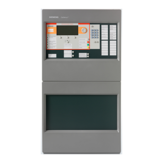
Indication and operating elements C-WEB network 6 Indication and operating elements Fire control Fire terminal LED module Floor repeater Floor repeater Cerberus panel FC72x FT724 FTO2008 terminal FT2010 display FT2011 Remote Indication Alarm Pre-alarm Fault Isolation Test mode Technology Activation... - Page 44 Indication and operating elements C-WEB network Cerberus Figure 18: Operation and display front of Cerberus PRO fire control panel Display, illuminated with plain text display Cursor keypad for navigation/selection of menu items Menu button Keypad (for direct selections by entering numbers and/or entering and changing objects-specific display texts) C button (Cancel) and OK button (confirmation of selection) Menu-dependent function keys (softkeys)
-
Page 45: Extra Indication And Operating Devices
Indication and operating elements Extra indication and operating devices 6.1 Extra indication and operating devices The fire terminal is also provided for indication and operation as is the floor repeater terminal and floor repeater display although these two offer only restricted functions. -
Page 46: Commissioning
Commissioning Extra indication and operating devices 7 Commissioning This chapter describes initial commissioning of the Cerberus PRO fire control panel (individual control panel, not networked). ● Activating access level ● Start auto-configuration ● Display C-NET line devices ● Enter customer texts for the control panel, C-NET and individual line devices via the control panel keypad Figure 19: Line tester FDUL221 NOTICE... -
Page 47: Activating Access Level
Commissioning Activating access level 7.1 Activating access level The 'Station' is protected against unauthorized operation by access levels. Authorization for access level 3 is needed for the functions described below. If the authorization code is not entered, operation is only possible in access level 1 (guest), e.g., for acknowledging the control panel buzzer or scrolling through the display messages. -
Page 48: Auto-Configuration Of Control Panels
Commissioning Auto-configuration of control panels 7.2 Auto-configuration of control panels This function requires the control panel, components, and C-NET to have been correctly installed. Once auto-configuration is complete, the control panel is ready for detection with limitations. A fire is recognized by the connected fire detectors and displayed on the control panel. -
Page 49: Auto-Configure Line
Commissioning Auto-configuration of control panels 7.2.1 Auto-configure line The 'Line' element category in the 'Maintenance' menu facilitates the reading-in of the current topology, for example. This creates part of the elements in the 'Detection tree'. NOTICE Overwriting an existing configuration Parts of an existing customer-specific configuration are lost. - Page 50 Commissioning Auto-configuration of control panels Display for auto-configuration Main menu Access level 3 Exit with <C> Message summary Element search Functions Event memory Favorites Login/logout Topology Settings/administration Function Function On/Off test Select 'Topology', continue with <ok> κ Topology Access level 3 Exit with <C>...
- Page 51 Commissioning Auto-configuration of control panels 007 Elements Module 2 'C-NET line card (onboard/FCL2001)' Line Line Line Line Line Line Line Line Upper Lower More level level Options Select 'Line 1', continue with 'More Options' <softkey 3> κ Selecting option Execute commands Show details Select 'Execute commands', continue with <ok>...
-
Page 52: Displaying C-Net Devices
Commissioning Displaying C-NET devices 7.3 Displaying C-NET devices After auto-configuration, the individual C-NET detector lines and the associated C- NET devices of each line can be displayed and configured. Depending on the control panel type (2 or 4 loops) and the control panel design, the depiction may vary and several lines may be displayed. - Page 53 Commissioning Displaying C-NET devices Example of selecting a line 004 Elements Module 2 C-NET line card (onboard/FCL2001) Line Line Line Line Line Line Line Line Upper Lower More level level Options 004 Elements Line 12 Device OH720 Device HI720 Device OP720 Device OP720...
-
Page 54: Entering/Changing Customer Text
Commissioning Entering/Changing customer text 7.4 Entering/Changing customer text You can enter customer text for any element on the control panel, independently of Cerberus-Engineering-Tool. Once customer text has been entered or changed, the updated display is only shown the next time the element is accessed. Entering or changing customer text does not lead to a reboot. -
Page 55: Changing Access Authorization Pin
Commissioning Changing access authorization PIN 7.6 Changing access authorization PIN After successful commissioning, the 4-digit access authorization (PIN) for the corresponding access level must be changed. Keep the new PIN in a safe place. If the PIN is lost, a system reset must be undertaken to the station's factory setting. The control panel configuration, including all customer data, is cleared in the process. - Page 56 Commissioning Changing access authorization PIN 'Create PIN' ϖ You have the required authorization level. 1. Select 'Main menu' > 'Settings/administration' > 'Manage PINs'. 2. Select the 'Create PIN' menu item. 3. Enter an admissible access level. 4. Enter the PIN in accordance with the input fields and confirm with <ok>. ...
-
Page 57: Restart The Station
Commissioning Restart the station 7.7 Restart the station The configuration of the ↑ 'Station' remains the same. There are the following ways in which to restart the ↑ 'Station': ● Via the menu on the display ● PMI & mainboard FCM2004 and FCM2027: With the 'S32' button ●... - Page 58 Commissioning Restart the station PMI & mainboard FCM2004 and FCM2027 ϖ Switches S38-1 and S38-2 are set to the 'OFF' position on the PMI & mainboard FCM2004. On the PCB of the operating unit, press and hold down the 'S32' button for κ...
-
Page 59: Testing The Installation
Testing the installation Checking functions 8 Testing the installation The fire detection installation can be switched to 'Test' operation mode to check it is functioning properly. 8.1 Checking functions The table below shows the recommended intervals for checking functions. National specifications always take priority. -
Page 60: Glossary
Glossary Glossary Abbreviation for 'alarm indicator'. C-NET device A device connected to the C-NET detector line. Abbreviation for 'Central Processing Unit'. The computing unit of the fire control panel. The arrangement of operating and display elements on a fire control panel or on a fire terminal. -
Page 61: Index
Index Index PIN ..............47 Customer text Input dialog ............. 47 Entering / changing ......... 54 Manage, create, delete, change ...... 55 Releasing an access level ....... 47 Date Set ..............54 Releasing an access level ........ 47 Download center Restart URL .............. - Page 62 Issued by © Siemens Switzerland Ltd, 2009 Siemens Switzerland Ltd Technical specifications and availability subject to change without notice. Building Technologies Division International Headquarters Gubelstrasse 22 CH-6301 Zug +41 41-724 24 24 www.siemens.com/buildingtechnologies Document ID: A6V10211094_f_en_-- Manual FS720 Edition: 2015-12-15...
Need help?
Do you have a question about the FC72x and is the answer not in the manual?
Questions and answers