Advertisement
Quick Links
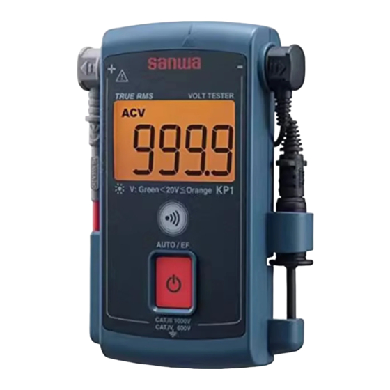
KP1
VOLT TESTER
INSTRUCTION MANUAL
Dempa Bldg., 4-4 Sotokanda 2-Chome
Chiyoda-ku, Tokyo, Japan
This manual emplys soy ink.
01-1410 2040 6010
[1] SAFETY PRE
CAU
TIONS
Before use, read the following safety precautions.
Thank you for purchasing our voltage tester equipped with the electric
field detection facility model KP1.
Before use, please read this manual thoroughly to ensure correct
and safe use. After reading it, keep it together with the product for
reference to it when necessary.
Using the product in a manner not specified in this manual may cause
damage to the protection function of the product.
The instructions given under the headings of " WARNING" and
" CAUTION" must be followed to prevent accidental burn and
electric shock.
1-1 Explanation of warning symbols
The meanings of the symbols used in this manual and attached to the
product are as follows:
: Very important instructions for safe use.
• The warning messages are intended to prevent accidents to
operating personnel such as burn and electric shock.
• The caution messages are intended to prevent incorrect
handling which may damage the product.
: Refer to Instruction Manual before use
: Double or reinforced insulation
: Ground
: Circuit continuity buzzer
: Backlight
1-2 Warning instructions for safe use
WARNING
The following instructions are intended to prevent injury such as burn
and electric shock. Be sure to follow them when using the instrument:
1. This instrument is a voltage tester equipped with the electric
field detection facility. Do not use it with an electric circuit
exceeding 1000 V.
2. Voltages over DC 70 V or AC 33 V rms (46.7 V peak) are
hazardous to human body. Take care so as not to touch them.
3. Never input signals exceeding the maximum rated input value
(see 1-3).
4. Never use the instrument for measuring a line connected to
equipment that may generate induced or surge voltage (such
as a motor) because an input exceeding the maximum
allowable overload input may be applied.
5. Never use the instrument if the instrument or test leads are
damaged or broken.
6. Never use the instrument with the case or battery lid removed.
7. During measurement, do not hold the instrument by a position
on the test pin side of the barrier on the test probe.
− 1 −
8. Never use the instrument when it is wet or with wet hands.
9. Never attempt repair or modification, except for battery
replacement.
10. Perform start-up inspection and inspect the instrument at least
once a year.
11. This instrument is for indoor use only.
12. Do not use the instrument in a method other than specified.
Otherwise, the protection function may be spoiled.
CAUTION
1. Accurate measurement may be impossible near a source of
strong magnetic field such as a transformer or large-current
line, near a source of electromagnetic wave such as a wireless
device or near a charged object.
2. This instrument may malfunction or the measurement result
may become abnormal if this instrument is used with a special
waveform such as that of an inverter circuit.
1-3 Overload protection
Max. overload
Mode
Display
Max. rated input
protection input
Self-test
Auto-identifying
1050 V rms,
AC/ DC 1000 V
voltage measurement
1450 V peak
Electric field detection
[2] APPLICATIONS AND FEATURES
2-1 Applications
This instrument is a voltage tester of the RMS value response type
equipped with the electric field detection facility. It is designed for
measurements in the ranges specified by IEC 61010-1 CAT. IV 600 V
and CAT. III 1000 V.
Recent multiinstruments have been increasing the facilities and
becoming capable of measuring a larger variety of items in simpler
ways. Nevertheless, this trend also means that the risk of operation
mistake is increasing because of the presence of facilities that are not
required by all of the users.
This instrument has been designed to meet the actual needs of the fields
of electrical equipment maintenance by prioritizing the usage without
operation mistakes, reducing the size for higher portability and limiting
the facilities to voltage measurement and electric field detection while
complying with safety standards. It is suitable for voltage measurement
and electric field detection of low-voltage lines and equipment.
2-2 Features
• Safe use with low-voltage equipment – IEC61010 CAT. IV 600 V
and CAT. III 1000 V compatibility.
• Single-button system – Easy operation for preventing operation
mistakes.
• Auto identification of AC or DC voltage – AC measurement in true
RMS value.
• Easy identification of 24 V type FA control panel voltage – The
backlight color changes at 20 V or more.
• Auto hold – The result of the last measurement is held
automatically.
• Self-test – Checking failures of the LCD or disconnection of a
lead wire.
• AC electric field detection – Both contact and noncontact
methods are available.
• Designed to fit the chest pocket of the working uniform.
• LED light for illuminating the working site.
Measurement Category (Overvoltage Category)
Measurement Category II (CAT. II):
Line on the primary side of equipment with power cord to be
connected to the receptacle.
Measurement Category III (CAT. III):
Line from the primary side or branch of equipment which directly
takes in electricity from a distribution board to the receptacle.
Measurement Category IV (CAT. IV):
Line from the service conductor to the distribution board.
− 2 −
[3] NAME OF COMPONENT UNITS
3-1 Main unit and test leads
Front
Back
EF detection antenna
LED light
Backlit LCD
Lead hook
VOLT TESTER
Detachable
probe
Lead holder
Magnet
Test probe
Probe holder
Buzzer LED
Lead reel
Strap hole
Power/Select button
TL-36: Test lead (black), approx. 1.5 m
TL-A01: Test probe (black)
Test pins
Φ4
plug
Barrier
Φ4
Barrier
plug
Φ4
plug
Test pins
Barrier
TL-35: Test probe (red)
3-2 Display
DC Voltage
Data Hold
AC Voltage
Low battery
indication
Live wire alarm
Minus sign
Numeric value
and decimal
point
[4] DESCRIPTION OF FUNCTIONS
4-1 Changing the measuring probe angle
T h e a n g l e o f t h e
measuring probe can
b e c h a n g e d b y
removing it from the
main body, positioning
it in the desired angle
and inserting it straight
into the main body.
Be sure to insert the
measuring probe all
the way until it is fixed.
4-2 Power/Select button
The function of the Power/Select button varies depending on the period
it is pressed. In this manual, we use the term "push" for the action of
pressing the button temporarily and the term "hold" for the action of
pressing and holding the button for more than one second.
Hold this button to turn the instrument ON/OFF. Note that the instrument
cannot be turned OFF while it is accepting an input.
Push the button while the instrument is ON to switch the measurement
modes.
The instrument is in the self-test mode (
displayed) when it is
turned ON. Thereafter, each press of this button switches the modes
in the following cycle. (For the description of each mode, see [5]
MEASUREMENT PROCEDURE.)
displayed) ⇒
Auto-identifying voltage measurement mode (
EF mode (
displayed) ⇒ Auto-identifying voltage measurement
mode ⇒ ... (repeat)
4-3 Auto power OFF
When the instrument is left without input for about one minute since the
last operation, Auto power OFF turns automatically the display and the
power of the instrument OFF. To recover from the auto power OFF, hold
the Power/Select button for more than one second.
4-4 Low battery alarm
When the built-in batteries have been discharged and the battery voltage
has dropped to below about 2.5 V,
mark appears on the display.
When this mark appears, replace both of the two batteries with new ones.
If the battery voltage drops below about 2.2 V,
appears on the
LCD and the instrument becomes unable to continue measurement.
− 3 −
4-5 Backlight and LED light
The LCD green backlight and the LED light light when the instrument
is turned ON. The backlight color changes to orange when the input
is AC or DC and 20 V or more, or when the AC live wire is detected in
the EF mode.
* The light cannot be turned OFF except by turning the instrument OFF.
4-6 Self-test
This self-test checks disconnection of the test lead wires, lack of
display segments and failure of the buzzer and buzzer LED light.
For details, see 5-2 Self-test mode.
4-7 AC/DC auto-identifying voltage measurement
When an input of 5 V or more is applied in the self-test or auto-identifying
voltage measurement mode, the instrument automatically identifies
whether the input is an AC or DC voltage and displays the measured value.
4-8 Auto hold
When the probe is separated from the measurement target during
auto-identifying voltage measurement or when the input drops below
about 5 V, the instrument automatically holds the last measurement
value displayed on the LCD. During auto hold,
appears on the
LCD and the displayed value flashes.
* A numeric value other than the measured value may appear momentarily
before the held value is displayed, but this is not malfunction.
4-9 EF (Electric Field) detection: EF button
This EF detection identifies the presence of voltage in a simple
manner by detecting an electric field generated by an AC voltage.
For details, see 5-4 EF (Electric Field) detection.
4-10 AC detection method
This instrument employs the RMS (Root-Mean-Square) method and
indicates the magnitude of AC current as the same amount of work as
DC. RMS values of sinusoidal waves and such non-sinusoidal waves
as square and chopping waves can be measured by the true RMS
circuit. (The input signal measurement value is used as the scale of the
actual input signal power so it is therefore measured as a more
effective value than the value obtained by average detection.)
4-11 CF (Crest Factor)
The CF (Crest Factor) indicates the peak value of a signal divided by
its RMS value. With most common waveforms such as sinusoidal and
chopping waves, the CF is relatively low.
With waveforms similar to pulse trains with low duty cycle, the CF is high.
For the voltages and CFs of typical waveforms, see the table below.
The CR of measurements should be 2 or less.
Root Mean
Average
Crest
Form
0 to PEAK
Value
Factor
Factor
Input Waveform
Square Value
Vp
Vrms
Vavg
Vp/Vrms Vrms/Vavg
π
Vp
2 Vp
Vp
-
-
√
2
-
Sinusoidal
√
π
√
π
2π
2
2
2
Vp
0
wave
p p
=0.637 Vp
=1.414 =1.111
=0.707 Vp
Vp
Square
Vp
1
1
Vp
Vp
0
wave
π
2π
Vp
Vp
2
-
-
-
√
3
Vp
Chopping
√
√
3
3
2
Vp
0
wave
π
2π
=1.155
=0.577 Vp
=0.5 Vp
=1.732
τ
τ
Vp
2π
2π
Pulse
-
・ Vp -
・ Vp
-
-
Vp
2π
2π
τ
τ
0
τ
2π
Voltages of Various Waveforms
4-12 Storage of lead
Lead holder: After winding the lead
around the lead reel for storage,
Lead hook
tuck the remaining section of the
lead in this space to prevent
spontaneous unwinding.
Lead hook: Hook the lead on these
p a r t s w h e n t h e l e a d i s u s e d
without unwinding fully.
Lead holder
Strap hole: Use this hole when attaching
a strap or like to the instrument.
Strap hole
[5] MEASURING PROCEDURE
WARNING
1. Do not apply an input signal exceeding the maximum rated input value.
2. During measurement, do not hold the instrument by a position on the
test pin side of the barrier on the test probe.
3. Use test leads matching the measurement category of the measured
point.
− 4 −
Advertisement

Related Manuals for Sanwa KP1


Summary of Contents for Sanwa KP1
- Page 1 Thank you for purchasing our voltage tester equipped with the electric 2 Vp • Single-button system – Easy operation for preventing operation - - √ - field detection facility model KP1. Sinusoidal √ π √ mistakes. T h e a n g l e o f t h e π...
- Page 2 Dimensions/mass approx. 205 g (including batteries) Sanwa reserves the right to inspect all warranty claims to determine the 5-3 Auto-detecting voltage measurement extent to which the warranty policy shall apply. This warranty shall not IEC61010-1, IEC61010-2-030 CAT. IV 600 V / CAT. Ⅲ...
Need help?
Do you have a question about the KP1 and is the answer not in the manual?
Questions and answers