Sign In
Upload
Manuals
Brands
Lenze Manuals
DC Drives
E84DGDVB5524
Lenze E84DGDVB5524 Manuals
Manuals and User Guides for Lenze E84DGDVB5524. We have
2
Lenze E84DGDVB5524 manuals available for free PDF download: Hardware Manual
Lenze E84DGDVB5524 Hardware Manual (172 pages)
L-force Drives
Brand:
Lenze
| Category:
Inverter Drive
| Size: 4 MB
Table of Contents
Table of Contents
3
1 About this Documentation
7
Validity Information
7
Document History
8
Conventions Used
9
Terms and Abbreviations Used
10
Notes Used
11
2 Safety Instructions
12
General Safety and Application Notes for Lenze Controllers
12
General Safety and Application Notes for Lenze Motors
15
Residual Hazards
18
3 Product Description
19
System Overview
19
Device Features
20
Identification
22
Product Key
23
Wiring Unit
23
Frame Unit
24
Communication Unit
25
Drive Unit
25
8400 Motec Set
26
Field Package Without Switch
27
Field Package with Switch
28
Overview of Control Terminals
29
4 Technical Data
30
General Data and Operating Conditions
30
Rated Data
35
Overview
35
Operation at Rated Mains Voltage 400 V
37
Operation with Increased Power at a 400 V Mains
39
Operation with Rated Mains Voltage 480 V
41
Operation with Increased Power on a 480 V System
43
Device Protection by Current Derating
45
Frame Unit / Field Package Without Switch
45
Frame Unit / Field Package with Switch
47
Overcurrent Operation
49
Switching Frequency Reduction
51
Power Terminals
52
8400 Motec 0.37
52
8400 Motec 4
55
8400 Motec Field Package
58
Control Terminals
61
Overview
61
General Data
62
As−Interface
63
Canopen
64
Ethercat
64
Ethernet/Ip™
65
Profibus
65
Profinet
66
Dimensions
67
Standard Motor Mounting
67
Field Package Without Switch
68
Field Package with Switch
69
5 Installation
70
Important Notes
70
Safety Instructions for the Installation According to UL/CSA
73
Installation According to EMC (Installation of a Ce−Typical Drive System)
75
Shielding
75
Motor Cable
76
Control Cables
77
Detecting and Eliminating EMC Interferences
77
Installation of 8400 Motec Pre−Assembled on the Motor
78
Installation Instructions
78
Plug at the Wiring Unit
78
Attaching the Cable Gland
79
Retrofitting the 8400 Motec Controller
81
Installation Instructions
81
Preparing a Motor for the 8400 Motec Installation
81
Mounting the Wiring Unit
82
Mounting of the Communication Unit
84
Settings at the Drive Unit
85
Mounting of the Drive Unit
85
Measures When Drive Is Used in IT Systems
86
Wall Mounting
87
Installation Instructions
87
Wall Adapter for 0.37
88
Wall Adapter for 4
89
Frame Unit / Field Package Without Switch
90
Frame Unit / Field Package with Switch
90
Power Terminals
91
Control Terminals
94
Basic I/O
94
Standard I/O
95
Extended I/O
96
As−Interface
97
As−Interface STO
99
Canopen
101
Canopen® STO
103
Ethercat
105
Ethercat® STO
107
Ethernet/Ip™
109
Ethernet/Ip™ STO
111
Profibus
113
Profibus® Sto
115
Profinet
117
Profinet® Sto
119
6 Commissioning
121
Before You Start
121
Handling the Memory Module
123
Commissioning Via DIP Switch/Potentiometer
125
DIP Switch / Potentiometer Assignment 0
128
DIP Switch / Potentiometer Assignment 1
131
Before Switching on
135
Commissioning Steps
136
Commissioning Via the Diagnosis Terminal
137
Display Elements and Function Keys
138
Menu Structure
139
User Menu
140
Commissioning Steps
141
SET Mode
144
Diagnostics
145
7 Braking Operation
146
Braking Operation Without Additional Measures
146
Braking Operation with Brake Resistor
147
Selection of the Brake Resistors
147
Wiring of Brake Resistor
148
Operation with Spring−Applied Brake
151
Introduction
151
Wiring
151
8 Safety Engineering
152
Introduction
152
Important Notes
153
Hazard and Risk Analysis
154
Standards
154
Basics for Safety Sensors
155
Operating Mode
156
Introduction
156
Disconnecting Paths
156
Safety Status
156
Technical Data
157
Electrical Installation
159
Certification
160
9 Accessories (Overview)
161
Wall Mounting
161
Wall Adapter for 0.37
161
Wall Adapter for 4
162
Frame Unit Without Switch
162
Frame Unit with Switch
163
Plug Connectors
164
M12 Plug−In Connector
164
Plug−In Modules
164
Memory Module
165
Diagnosis Terminal
166
Switch/Potentiometer Unit
167
External Brake Resistors − Mounting Variant
168
External Brake Resistors
169
10 Appendix
170
Total Index
170
Advertisement
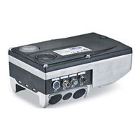
Lenze E84DGDVB5524 Hardware Manual (124 pages)
L-force Drives. Decentralised frequency inverter. 0.37 ... 7.5 kW. E84DG series
Brand:
Lenze
| Category:
DC Drives
| Size: 2 MB
Table of Contents
Table of Contents
3
1 About this Documentation
7
Validity Information
7
Document History
8
Conventions Used
9
Terms and Abbreviations Used
10
Notes Used
11
2 Safety Instructions
12
General Safety and Application Notes for Lenze Controllers
12
General Safety and Application Instructions for Lenze Motors
15
Residual Hazards
18
3 Product Description
19
System Overview
19
Device Features
20
Identification
21
Type Code
22
Introducing Information
22
The Type Codes
22
Overview of Control Terminals
25
4 Technical Data
26
General Data and Operating Conditions
26
Rated Data
31
Overview
31
Operation at Rated Mains Voltage 400 V
33
Operation at Increased Rated Power at 400 V Mains Voltage
35
Operation with Rated Mains Voltage 480 V
37
Switching Frequency Reduction
39
Overcurrent Operation
40
Terminal Description
42
Overview
42
Power Terminals
44
Mains Connection
45
Motor Connection
45
Motor Temperature Monitoring
45
Motor Holding Brake Connection
45
Connection of Brake Resistor
45
Control Terminals
46
Digital Inputs
48
Digital Output
50
Analog Input
50
Connection of Relay Output
50
Communication Connection
51
Dimensions
52
Standard Motor Mounting
52
Wall Mounting
53
5 Installation
54
Important Notes
54
Safety Instructions for the Installation According to UL/CSA
57
Safety Instructions for the Installation According to UL/CSA
58
Installation According to EMC (Installation of a CE-Typical Drive System)
59
Shielding
59
Motor Cable
60
Control Cables
61
Detecting and Eliminating EMC Interferences
61
Mechanical Installation
62
Electrical Installation
63
Power Connections
63
Wiring of Control Connections
64
Installation of 8400 Motec Pre-Assembled on the Motor
66
Plug at the Wiring Unit
66
Attaching the Cable Gland
67
Retrofitting the 8400 Motec Controller
69
Preparing a Motor for the 8400 Motec Installation
69
Mounting the Wiring Unit
70
Mounting of the Communication Unit
71
Settings at the Drive Unit
72
Mounting of the Drive Unit
72
Measures When Drive Is Used in IT Systems
74
Wall Mounting of 8400 Motec Controller
75
6 Commissioning
76
Before Switching on
76
Quick Commissioning
78
General Configuration Settings
79
Commissioning Steps
85
Handling of the Keypad
86
Overview of the Commissioning Steps with Keypad
89
Keypad Control
89
Short Overview of the Parameters for Quick Commissioning
93
Setting with the Diagnosis Terminal (Keypad)
94
Diagnostics
95
Drive Diagnostics Via the Integrated Display
95
Diagnostic Codes
95
7 Braking Operation
96
Braking Operation Without Additional Measures
96
Braking Operation with Brake Resistor
97
Selection of the Brake Resistors
97
Wiring of Brake Resistor
98
Operation with Spring-Applied Brake
101
Introduction
101
Wiring
101
8 Safety Engineering
102
Introduction
102
Important Notes
103
Hazard and Risk Analysis
104
Standards
104
Basics for Safety Sensors
105
Operating Mode
106
Introduction
106
Disconnecting Paths
106
Safety Status
107
Technical Data
108
Electrical Installation
110
Certification
111
9 Accessories (Overview)
112
Adapter Plates (Accessories)
112
Plug Connectors
113
Internal Brake Resistors
114
External Brake Resistors
115
Communication Modules
116
Canopen
116
Profibus
116
AS Interface
116
Profinet
117
Ethercat
117
Ethernet/Ip
117
Keypad
118
Safety Engineering
119
10 Appendix
120
Total Index
120
Advertisement
Related Products
Lenze E84DGDVB3714
Lenze E84DGDVB5514
Lenze E84DGDVB7514 E84DGDVB1124
Lenze E84DGDVB2224
Lenze E84DGDVB3024
Lenze E84DGDVB4024
Lenze E84DGDVB7524
Lenze E84DGDVB7514
Lenze E84DGDVB1124
Lenze E84DGDVB1524
Lenze Categories
DC Drives
Control Unit
Inverter
Engine
Controller
More Lenze Manuals
Login
Sign In
OR
Sign in with Facebook
Sign in with Google
Upload manual
Upload from disk
Upload from URL