
Related Manuals for Gorilla Playsets 2250


Summary of Contents for Gorilla Playsets 2250
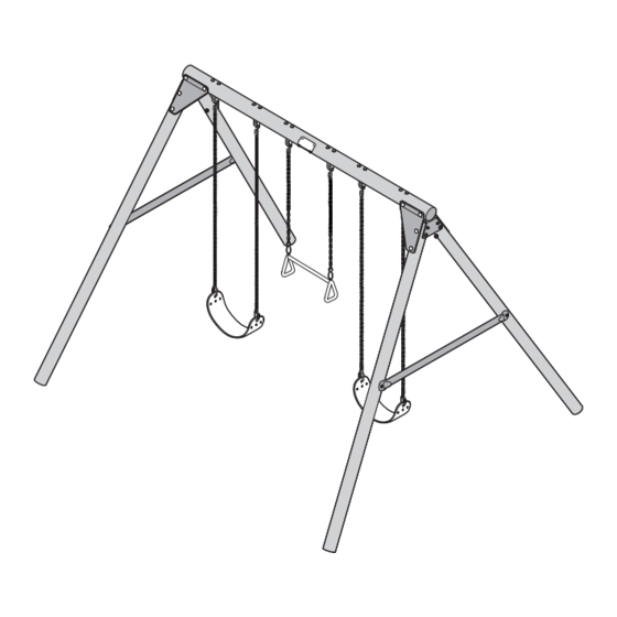
- Page 1 Roundabout Freestanding Swing Set Model: 2250 Boxes: 1 - Wood Posts, Brackets, Hardware, Stakes, and Swings Copyright © 2018 Gorilla Playsets All Rights Reserved 190 Etowah Industrial Court Canton, GA 30114 www.gorillaplaysets.com...
- Page 3 This decision is subject to verification of the defect, which, at Gorilla’s discretion, may be accomplished by submitting photographs or by delivery of the defective part to Gorilla Playsets • 190 Etowah Industrial Ct. • Canton, GA 30114 • 1-800-882-0272 Monday to Friday 9AM-5PM EST. Any warranty claim must include proof of purchase, including the date of purchase.
-
Page 4: Important Safety Guidelines
Gorilla shall not be liable for incidental, indirect or consequential damages or injuries that result from building and/or playing on our play sets. Adult supervision is recommended anytime a play set is being used. WEIGHT LIMITS FOR GORILLA PLAYSETS • SWING BELT: 225 LBS. • TRAPEZE: 125 LBS. - Page 5 ROUNDABOUT FREESTANDING SWING SET...
- Page 6 THIS PAGE INTENTIONALLY LEFT BLANK...
-
Page 7: Important - Please Read
IMPORTANT – PLEASE READ Congratulations! You have just purchased one of the finest residential wooden swing sets available today. As with any wooden product that spends its entire life outside, in varying elements, it is important to know what to expect with your new swing set so that your family can enjoy it for many years. - Page 11 Play Set Surfacing Recommendations: Below are some of the recommendations that the U.S. Consumer Product Safety Commission (CPSC) offers from its Handbook for Public Playground Safety. The guide can be downloaded in full at www.cpsc.gov/PageFiles/122149/325.pdf 1. Protective Surfacing - Since almost 60% of all injuries are caused by falls to the ground, protective surfacing under and around all playground equipment is the most critical safety factor on playgrounds.
- Page 12 2. Fall Zones - A fall zone, covered with a protective surfacing material, is essential under and around equipment where a child might fall. This area should be free of other equipment and obstacles onto which a child might fall. Stationary climbing equipment and slides should have a fall zone extending a Minimum of 6’...
- Page 13 PLAYGROUND SURFACING MATERIALS SECTION 4 OF THE CONSUMER PRODUCT SAFETY COMMISSION'S OUTDOOR HOME PLAYGROUND SAFETY HANDBOOK Select Protective Surfacing One of the most important things you can do to reduce the likelihood of serious head injuries is to install shock-absorbing protective surfacing under and around your play equipment.
-
Page 14: Swing Beam Loading
SWING BEAM LOADING Weight Limits for Accessories: The weight limit for a Swing Belt is 225 lbs. (Although 100 lbs is the maximum recommended swinging weight capacity for the swing position.) The weight limit for a Trapeze Bar is 125 lbs. (Although 100 lbs is the maximum recommended swinging weight capacity for the swing position.) Maximum Allowable swinging weight for a three position swing: 1) The maximum allowable swinging weight at each Swing Belt position is 100 lbs. -
Page 15: Safety Zone
SAFETY ZONE 13'-4" 6' R 7'-0" Height 8'-0" 26'-8" 13'-4" 9'-5" 21'-5" MINIMUM USE ZONE FOR PLAY EQUIPMENT SHALL EXTEND NO LESS THAN 72" FROM ALL SIDES OF THE PLAY STRUCTURE. SWING USE ZONE EXTENDS NO LESS THAN 160". SWINGS MUST HAVE A MINIMUM CLEARANCE OF 8" ABOVE THE PROTECTIVE SURFACING. -
Page 16: Tools Required
TOOLS REQUIRED TAPE MEASURE DRILL PHILLIPS HEAD 1/2” & 9/16’’ SOCKETS HAMMER ADJUSTABLE DRIVE & WRENCH WRENCH SCREWDRIVER LADDER SAFETY GLASSES 1/4" DRILL BIT PLIERS INCLUDED HARDWARE 3/8 x 5-1/2" carriage bolts (x12) 3/8" Flat Washer (x30) 3/8 x 5" carriage bolts (x4) 3/8 x 4"... - Page 17 COMPONENTS 4" Dia. x 93" Plastic-coated Post (x1) 99-0715 3-1/4" Dia. x 93" Plastic-coated Post (x4) 99-0714 1" Dia. x 49" A-Frame Brace (x2) 11-5022 2447R 2448L 2449 Swing Beam Bracket Right 2447R (x2) Swing Beam Under Beam 2449 (x2) Gorilla Mini Logo Plate (x1) Swing Beam Bracket Left 2447L (x2) 11-4027...
- Page 18 1/4 x 2-1/2" Panhead Screw 1/4" lock washer 1/4" flat washer Note: Locate (3) pre-drilled A-Brace holes facing up. Note: Fasteners should be snug at this point. You will assemble two A-frame post assemblies. 1. Move posts apart. 2. Place the holes in the A-brace over the holes in the posts. 3.
- Page 19 If needed, rotate poles to help with alignment 3/8 x 2-1/2" Lag Screw 1/4 x 2-1/2" 3/8" lock washer Panhead Screw Fig. 1 3/8" flat washer 1/4" lock washer 1/4" flat washer Tighten securely after L-bracket is attached Fig. 2 A-brace (2) Holes this end Support...
- Page 20 3/8 x 4" Carriage bolt bolt cap 3/8" lock nut 3/8" flat washer 1. Carefully flip the A-frame over. 2. Remove any wood or plastic material in hole openings. Attach two brackets to the post as shown. Tighten fasteners slightly snug at this point. Do NOT fully tighten. 3.
- Page 21 3/8 x 5-1/2" Carriage Bolts Torque Washer Mini Swing Hanger 3/8" Washer 3/8" Lock Nut Bolt Cap 1. Line up the holes of the Mini Swing Hangers with the holes in the Swing Beam. 2. Fasten the Mini Swing Hangers to the Swing Beam using 5-1/2" carriage bolts with Torque Washers on top of the Swing Beam, and 3/8"...
- Page 22 3/8" lock nut bolt cap 3/8" flat washer This hole empty. 3/8 x 5" Carriage bolt Loosen these if you have trouble getting the beam to fit in between the swing brackets. 1. Remove any wood or plastic material in hole openings. Locate the swing beam between the brackets and attach as shown. HINT: Loosen bolts in 3-1/4"...
- Page 23 3/8" lock nut bolt cap 3/8" flat washer 3/8 x 5" Carriage bolt 1. Carefully swing the A-frame assembly up and insert a second bolt. Attach as shown. Tighten fasteners slightly snug at this point. Do NOT fully tighten.
- Page 24 bolt cap 3/8" lock nut 3/8" flat washer Leave this hole empty 3/8 x 5" Carriage bolt 1. Locate the second A-frame assembly and remove any wood or plastic material in hole openings. Attach to swing beam as shown. HINT: Loosen bolts in 3-1/4" posts to help align holes for 5" bolts if necessary. Tighten fasteners slightly snug at this point.
- Page 25 3/8" lock nut bolt cap 3/8" flat washer 3/8 x 5" Carriage bolt Tighten ALL Lock nuts 3/8" flat washer until 2 threads minimum 3/8" lock washer extend past nut. 3/8 x 2-1/2" Lag screw Swing A-Frame up 1/4" Pre-drill 1.
- Page 26 Hanging Swings 1. Hang the Trapeze Swing in the center position only. Place the end of the chain on the hook end of the Mini Swing Hanger. You may adjust the height of the Trapeze up or down by clipping onto other chain links. 2.
- Page 27 Logo Plate Centered on Swing Beam Logo Plate 1. Bend the Logo Plate over one of the Swing Legs until it matches the Swing Beam curvature closely. 2. Place the Logo Plate centered on the Swing Beam on the front side. 3.
- Page 28 Safety Warning Label Fold up 5/16” Washer 1-1/2” Anchor-It Lag Screw Strap Anchor-It 1 At locations circled above, twist the Anchor-It into the ground until only the loop is exposed. 2. Place Anchor-It Strap thru loop, fold the ends together and attach to the unit as shown. Note: Keep as little play as possible using the top pair of holes in the strap.
Need help?
Do you have a question about the 2250 and is the answer not in the manual?
Questions and answers