Table of Contents
Advertisement
Quick Links
Advertisement
Table of Contents

Subscribe to Our Youtube Channel
Related Manuals for Gorilla Playsets Landing


Summary of Contents for Gorilla Playsets Landing
- Page 1 ® Ladder (hidden behind slide) Landing ASSEMBLY MANUAL Copyright © 2011 Gorilla Playsets All Rights Reserved Gorilla Playsets • 190 Etowah Industrial Court Canton, GA 30114 (800) 882-0272 • www.gorillaplaysets.com Latest Revision: January 12, 2011...
- Page 2 TABLE OF CONTENTS Warranty and Safety Guidelines………………………………………..……...Pages 3-10 Leveling Fort, General Information and Site Plan...........Pages 10-14 Kit Contents and Tool List…………..………………………………………....Page 15 Hardware, Lumber Checklist and Accessory Checklist......…..Pages 16-29 Corner Post Layout and Adding T-Nuts to Corner Posts...……..………...…..Steps 1-2 Framing Fort……………………………………..…………………………..……..
-
Page 3: Important - Please Read
We appreciate your purchase and know that you will enjoy your play system for many years to come. IF YOU HAVE MISSING OR DAMAGED PARTS OR NEED ASSISTANCE ASSEMBLING, PLEASE CALL Gorilla Playsets MANUFACTURING DIRECT. (800) 882-0272 FACTORY HOURS – MON.–FRI., 8AM-5PM EST DO NOT RETURN THIS PRODUCT TO THE RETAILER OR CONTACT THE RETAILER DIRECT. - Page 4 Quality Lumber At Gorilla Playsets, we use only the finest, hand selected lumber available. You can be assured that our lumber is strong, durable, and conforms to the national standards for use in children’s play equipment. It’s this quality that allows us to offer a 10 year warranty on the lumber used in our play sets.
-
Page 5: Limited Manufacturer's Warranty
Limited Manufacturers Warranty Gorilla Playsets® (“Gorilla”) warrants its play sets to be free from defects in workmanship and materials, under normal use and conditions at its original installation, for 10 years for structural wood components and for one year for all other components (e.g., hardware, plastics, tarps, rope ladder, etc.) -
Page 6: Important Safety Guidelines
Gorilla shall not be liable for incidental, indirect or consequential damages or injuries that result from the building and/or playing on our play sets. Adult supervision is recommended anytime a play set is being used. WEIGHT LIMITS FOR GORILLA PLAYSETS • FORT PLATFORMS: 800 LBS. TOTAL WEIGHT • SWING BELTS: 175 LBS. - Page 7 Safety and Maintenance Tips for Your New Play Set: NOTE: Your children’s safety is our #1 concern. Observing the following statements and warnings reduces the likelihood of serious or fatal injury. Please review these safety rules regularly with your children. •...
- Page 8 Safety and Maintenance Tips for Your New Play Set: (continued) Playgrounds should be inspected on a regular basis. If any of the following conditions are noted, they should be removed, corrected, or repaired immediately to prevent injuries. • Hardware that is loose, worn or that has protrusions or projections. •...
- Page 9 Play Set Surfacing Recommendations: Below are some of the recommendations that the U.S. Consumer Product Safety Commission (CPSC) offers from its Handbook for Public Playground Safety. The guide can be downloaded in full at www.cpsc.gov/cpscpub/pubs/325.pdf 1. Protective Surfacing - Since almost 60% of all injuries are caused by falls to the ground, protective surfacing under and around all playground equipment is the most critical safety factor on playgrounds.
- Page 10 2. Fall Zones - A fall zone, covered with a protective surfacing material, is essential under and around equipment where a child might fall. This area should be free of other equipment and obstacles onto which a child might fall. Stationary climbing equipment and slides should have a fall zone extending a minimum of 6’...
- Page 11 General Info to Review Before Installation • Depending on your experience, assembly of Gorilla Playsets can take as little as 6 hours up to 24 hours, depending on size, after inventory of parts; therefore, we recommend you set aside a full two days for assembly.
- Page 12 This page is a list of definitions and explanations used throughout our instructions to aid you in the assembly of your play set. Offset Holes- Throughout the installation procedures we will refer to parts with offset holes. This refers to the orientation of the holes on the board. An offset hole is one that is closer to one side than it is the other or in other words, it is not centered on the board.
- Page 13 Common Installation Practice Installing T-nuts When installing T-nuts into the wood, use a smooth faced hammer to set the face of the T-nut flush into the wood Corner Post Insert the barrel of the T-nut into the T-nut predrilled hole. Using a smooth faced hammer, drive the T-nut until the face of the T-nut is flush to the wood.
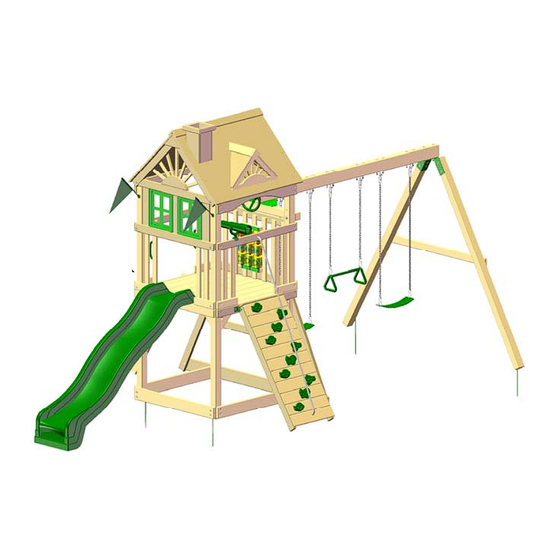
- Page 14 Please familiarize yourself with the manual, parts/components and general construction process of your new playset before getting started. SITE PLAN: Ladder Swing Belts (2) Trapeze Arm (1) Wave Slide Rock Wall Playset height: 10’ - 4-1/2” Approximate assembly time: 6-8 Hours (6) foot unobstructed safety perimeter around playset recommended.
-
Page 15: Required Tool List
Swings, Slides, Accessories: ___ (Qty ) Description ___ (2) Swingbelts w/ Chains ___ (1) 8ft. Wave Slide ___ (1) Landing Assembly Manual ___ (10) Rock Wall Grips ___ (1) Trapeze Bar w/ Chains ___ (1) Telescope ___ (1) Steering Wheel... - Page 16 Use the ruler to the right to measure your bolts and screws. Picture views shown below are 1:1 scale and can be used to match bolt and screw sizes. #8 x 1 ¼” Wood Screw QTY: 10 #8 x 1-½” Wood Screw QTY: 104 #8 x 2”...
- Page 17 Use the ruler to the right to measure your bolts and screws. Picture views shown below are 1:1 scale and can be used to match bolt and screw sizes. 3/8 x 3 ½” 5/16 x 3 ½” Hex Lag Hex Lag Screw Screw QTY: 26 QTY: 12...
- Page 18 Picture Description Qty. 1 x 5 x 52” Roof Finisher (Tongue Only) 1 x 5 x 52” Roof Starter (Groove Only) 1 x 5 x 52” Roof Board (Tongue and Groove) 3-1/2 x 3-1/2 x 52” Roof Peak 2 x 4 x 12” Bottom Panel Board - Left 2 x 4 x 12”...
- Page 19 Picture Description Qty. 2 x 4 x 13” Angle Support 2 x 4 x 17” Ladder Step 2 x 4 x 35-1/2” Roof Support - Left 2 x 4 x 35-1/2” Roof Support - Right 2 x 4 x 43-3/4” Sun Support 2 x 4 x 47-3/8”...
- Page 20 Picture Description Qty. 2 x 4 x 47-3/8” Panel & Deck Support 2 x 4 x 47-3/8” Rock Wall Side Top Panel Board 2 x 4 x 47-3/8” Stringer 2 x 4 x 48” Fort Support 2 x 4 x 57” Ladder Left Side 2 x 4 x 57”...
- Page 21 Picture Description Qty. 2 x 4 x 57” Rock Wall Side 2 x 4 x 58” Swing Leg Cross Member 2 x 6 x 16” 2 x 6 x 47-3/8” Arched Side Top Board 2 x 6 x 47-3/8” End Sandbox Board 2 x 6 x 86”...
- Page 22 Picture Description Qty. 4 x 4 x 47-3/8” Swing Beam Support 4 x 4 x 96” Front Corner Post 4 x 4 x 96” Rear Corner Post 4 x 4 x 96” Swing Leg 4 x 6 X 108” Swing Beam 5/4 x 2 x 13”...
- Page 23 Picture Description Qty. 5/4 x 2 x 17” Large Ray 5/4 x 2-1/4 x 11- 1/2” Horizontal Window Support 5/4 x 3 x 28” Panel Slat 5/4 x 3 x 23-7/8” Rock Wall Top 5/4 x 4 x 18-1/2” Ladder Back 5/4 x 4 x 40-1/2”...
- Page 24 Picture Description Qty. 5/4 x 6 x 10-1/2” Roof Peak Support 5/4 x 5 x 23-7/8” Bottom Rock Wall Board 5/4 x 5 x 23-7/8” Rock Wall Board 5/4 x 6 x 20” Vertical Window Support 5/4 x 6 x 47-3/8” Deck Board ®...
- Page 25 Picture Description Qty. 8’ Wave Slide Swings w/Chains Trapeze Bar w/Chains ® Page 25...
- Page 26 Picture Description Qty. Swing Plate Climbing Rocks A-Frame Swing Leg Bracket Not Shown Hardware Box Instructions ® Page 26...
- Page 27 Picture Description Qty. Iron Ductile Swing Hangers 90 º Green Bracket Spring Clip Unassembled Tic Tac Toe panel Tic Tac Toe Boards 1-3/8” x 1-5/8” x 10-1/2” ® Page 27...
- Page 28 Picture Description Qty. 10’ Rope Plastic Window Flag Kit Ground Stake ® Page 28...
- Page 29 Picture Description Qty. Telescope Steering Wheel Safety Handle Unassembled Chimney Unassembled Dormer ® Page 29...
- Page 30 Step 1: Corner Post Layout 1: This step is critical to building the fort properly. If any mistakes are made here, you will need to dis-assemble and then re-assemble to make your corrections. 2: Lay out each of the 4 x 4 x 96” Corner Posts in the area you intend on building the fort side of the playset.
- Page 31 Step 2: Inserting T-Nuts Into Corner Posts 1: Use a hammer to seat the t-nuts after inserting them into the holes shown in the diagram below. 2: The barrel of the t-nut should go in the hole first. Hammer the t-nut until it is flush/ almost flush to the corner posts.
- Page 32 Step 3: Sandbox And Panel Support Board 1: The 2 x 6 x 47-3/8” End Sandbox Board (with four pre-drilled holes) attaches to the bottom of the Front Corner Posts, offset holes down with two 5/16” x 4-1/2” hex bolts and two 5/16”...
- Page 33 Step 4: Rear Sandbox/Panel Support Board 1: The 2 x 4 x 47-3/8” Panel Support (offset holes down) attaches to the back side of the Rear Corner Posts with two 5/16” x 4-1/2” hex bolts and two 5/16” washers. 2: The 2 x 6 x 86” Rear Sandbox Board (offset holes down) attaches to the back side of the Rear Corner Posts with two 5/16”...
- Page 34 Step 5: Sandbox Boards and Panel Support 1: The 2 x 4 x 47-3/8” Panel Supports (offset holes up) attach to the sides of the front and rear corner posts with two 5/16” x 4-1/2” hex bolts and two 5/16” washers. 2: Attach the top holes in the 2 x 6 x 47-3/8”...
-
Page 35: Step 6: Deck Supports
Step 6: Deck Supports 1: Attach one Deck Support (offset holes down) to the inside of the Front and Rear Corner Posts with two 5/16” x 4-1/2” hex bolts and 5/16” washers. Note: One Panel Support Board was removed for clarity. 2 x 4 x 47-3/8”... - Page 36 Step 7: Leveling the Play Set and installing Lag Screws 1: Level your play set frame. Level side to side and front to back. Check the diagonals for square. Once you have a level and square play set frame you may install lag screws.
- Page 37 Step 8: Fort Supports 1: Place a 5/16” Tee Nut into the hole in the Fort Supports as shown. 2: From the Rear side of the Rear Panel Board loosely attach each Fort Support with one 5/16” x 2-1/2” Hex Bolt and one 5/16” washer. 3: Measure 2”...
- Page 38 Step 9: Deck Spacers 1: Place a 5/4 x 4 x 40-1/2” Deck Spacer between the Front and Rear Corner Posts on top of the Deck Supports as shown below. 2: The Deck Spacer side should be flush with the inside of the Panel Support. 3: Attach each Deck Spacer to the Deck Supports with two 2”...
- Page 39 Step 10: Deck Stringer 1: Center the 2 x 4 x 47-3/8” Deck Stringer underneath the Deck Spacers. 2: Attach the Deck Stringer to the Deck Spacers with two 2” Wood Screws. 2” Wood Screw 2 x 4 x 47 3/8” Deck Stringer ®...
- Page 40 Step 11: Face Boards 1: Locate two 2 x 4 x 47-3/8” Face Boards. 2: Attach a Face Board to the front of the Front Corner posts making sure the top side is flush with the top side of the Panel Supports. 3: Attach the Face Board with six 2-1/2”...
-
Page 41: Step 12: Ladder Assembly
Step 12: Ladder Assembly 1: Lay one 2 x 4 x 57” Ladder Side on a flat surface with channels facing down. Place the barrel of a T-Nut in the hole at the top of the Ladder Side, and secure with a hammer. - Page 42 Step 13: Attaching The Ladder 1: The Ladder attaches to the left side of the play set, 14-7/16” from the outside edge of the front corner post. 2: Make sure the ladder is level. The bottom edge of the 90 brackets should be 3/4”...
- Page 43 Step 14: Deck Boards 1: Seven 5/4 x 6 x 47 3/8” Deck Boards will lay across the Deck Supports, flush to the Face Boards. There will be approximately a 1/4” gap between each Deck Board. 2: Space the Deck Boards evenly across the supports. 3: Secure each Deck Board to the Deck Supports and the Deck Stringer with five 2”...
- Page 44 Step 15: Panel and Panel Support Boards 1: Place the 2 x 4 x 12” Bottom Panel Board - Left and 2 x 4 x 12” Bottom Panel Board - Right on top of the 2 x 4’s as shown below with offset holes up. Attach each Bottom Panel Board with one 5/16”...
- Page 45 Step 16: Panel Boards 1: Place the 2 x 4 x 12” Bottom Panel Board - Left and 2 x 4 x 12” Bottom Panel Board - Right on top of the 2 x 4 at the front of the play set as shown below with offset holes down.
-
Page 46: Step 17: Panel Slats
Step 17: Panel Slats 1: Locate nineteen 5/4 x 3 x 28” Panel Slats. Four Panel Slats will be installed at both the left, right and front of the play set. Seven Panel Slats will be installed at the rear of the play set.. -
Page 47: Step 18: Rock Wall
Step 18: Rock Wall 1: Locate two 2 x 4 x 57 Rock Wall Side boards. Lay the boards out as shown and insert a 5/16” t-nut into the hole on the inside of each board. Use a hammer to set each t-nut flush with the board. - Page 48 Step 19: Rock Wall 1. Locate ten 5/4 x 5 x 23-7/8” Rock Wall Boards and one 5/4 x 5 x 23-7/8” Bottom Rock Wall Board with one big hole in it. 2. Place one Rock Wall Board at the top of the Rock Wall Sides nearest the holes where you previously installed the tee nuts.
- Page 49 Step 20: Rock Wall 1. Locate two 90 Green Brackets, two 5/16” washers and two 5/16” x 1-1/2” hex bolts. 2: Fasten the tapered side of each 90 Green Bracket to each Rock Wall Side with a 5/16” x 1-1/2” hex bolt and 5/16” washer. 5/16”...
- Page 50 Step 21: Rock Wall 1: Locate two bags of Climbing Rocks. Inside each bag should be five rocks, fifteen #14 x 1-1/4” pan head screws and fifteen 1/4” flat washers 2: Place the Climbing Rocks in a staggered pattern on the Rock Wall Boards. Place one rock on each board except for the bottom rock wall board with the hole in it.
- Page 51 Step 22: Rock Wall 1: Place the 5/4 x 3 x 23-7/8” Rock Wall Top Cap on top of the Rock Wall Sides flush with the top Rock Wall Board. 2: Fasten the 5/4 x 3 x 23-7/8” Rock Wall Top Cap to the Rock Wall Sides and the top Rock Wall Board with four 2”...
- Page 52 Step 23: Attaching Rock Wall 1: The Rock Wall attaches to the right side of the play set, 11-3/4” from the outside edge of the rear corner post. 2: Make sure the Rock Wall is level. The bottom edge of the 90 brackets should be 3/4”...
- Page 53 Step 24: Swing Beam Support 1. The 4 x 4 x 47-3/8” Swing Beam Support has counter-sunk holes in the center and on the ends. Install the Swing Beam Support so that the counter-sunk holes on each end of the beam face out, and the counter-sunk holes in the center face down. 2.
-
Page 54: Step 25: Swing Beam Plate
Step 25: Swing Beam Plate 1: Place the Swing Beam Plate on top of the Swing Beam Support, lining up the pilot holes. 2: Fasten the Swing Beam Plate to the Swing Beam Support on the outside holes using 3/8” x 3-1/2” carriage bolts from the top and 3/8” washers with 3/8” lock nuts on the bottom. - Page 55 Step 26: Attach Swing Legs To Bracket 1: Place the 4 x 4 x 96” Swing Legs flush to the top of the Swing Leg Bracket. 2: Fasten the Swing Legs to the Swing Leg Bracket with eight 3/8” x 3-1/2” lag screws and eight 3/8”...
- Page 56 Step 27: Iron Ductiles 1: Line up the holes of the Iron Ductiles with the holes in the Swing Beam. 2: Fasten the Iron Ductiles to the Swing Beam using 3/8” x 7” carriage bolts with torque washers on top of the Swing Beam, and 3/8” lock nuts with 3/8” washers on the bottom. Place bolt caps over exposed threads after securing.
- Page 57 Step 28: Rest Swing Beam on Fort *Two people are required for this step. 1. Sit the swing beam legs upright. 2. Line up the pre-drilled holes and rest the swing beam on top of the fort and swing legs. Make sure the iron ductiles are facing down. ®...
- Page 58 Step 29: Swing Beam to Swing Legs 1: Fasten the Swing Beam to the Swing Leg Bracket using 3/8” x 6-1/2” carriage bolts with torque washers on top of the Swing Beam, and 3/8” lock nuts with 3/8” washers underneath. 2: Use a 3/8 x 3-1/2”...
- Page 59 Step 30: Swing Beam to Fort *An extra person is required for this step. 1: Have one person line up the hole in the end of the Swing Beam with the middle hole on the Swing Beam plate. The other person may have to carry the other end where the legs are located to accomplish this task.
- Page 60 Step 31: Level The Swing Beam 1: Place a level on top of the Swing Beam and adjust the legs in or out as needed to make the Swing Beam level. ® Page 60...
- Page 61 Step 32: Swing Leg Cross-Member 1: Position the 2 x 4 x 58” Swing Leg Cross-Member against the Swing Legs. 2: Level the Swing Leg Cross-Member, and secure to the Swing Legs with 3/8” x 3-1/2” lag screws and 3/8” washers. 3/8”...
- Page 62 Step 33: Arched Side Top Boards 1: Place one Arched Side Top Board on each side of the play set at the top. 2: Attach each Arched Side Top Board through the top hole into the t-nut in the corner post with 5/16”...
- Page 63 Step 34: Roof Supports 1: Attach one 2 x 4 x 35-1/2” Roof Support-Left and one 2 x 4 x 35-1/2” Roof Support- Right to the front and rear of the play set with 5/16” x 4-1/2” hex bolts and 5/16” washers.
- Page 64 Step 35: Roof Starters/Roof Peak 1: Place the 1 x 5 x 52” (groove only) Roof Starter Boards at the peak of the roof. The holes in the Roof Starters should be centered on the Roof Supports. The flat side of the Roof Starters should be placed as close together as possible near the peak without the boards overlapping.
- Page 65 Step 36: Roof Boards/Roof Finishers Chimney and Dormers 1: Place the 1 x 5 x 52” Roof Boards on top of the Roof Supports, fitting the tongue into the groove of the Roof Starter. The holes in the Roof Boards should be centered over the Roof Supports.
- Page 66 Step 37: Sun Support and Sun 1: Place a 2 x 4 x 43-3/4” Sun Support underneath the Roof Supports. Make sure the Sun Support is level. Attach the Sun Support through the pre-drilled holes in the bottom to the Roof Supports with two 2-1/2” wood screws. Repeat for the other side of the roof. 2: Place a 2 x 6 x 16”...
- Page 67 Step 38: Sun Rays 1: All the sun ray pieces get installed to the inside surface of the Roof Supports and Sun pieces. 2: Place the 5/4 x 2 x 17” Large Ray centered under the peak of the Roof Supports. Attach the Large Ray to the Roof Support and Sun with two 1-1/2”...
- Page 68 Step 39: Window Supports/Windows In this step the wood components to attach windows will be installed on the inside of the front of the playset. Go up on top of the deck and look out the front of the play set. 1: Attach the 5/4 x 6 x 20”...
-
Page 69: Step 40: Safety Board
Step 40: Safety Board This board is meant to be a visual deterrent to prevent children from running through the base of the play set into other children on the swing set. 1: Measure 17-1/4” from the top of the Rear Sandbox Board and make a mark on the rear corner posts. - Page 70 Step 41: Angle Supports 1: Four 2 x 4 x 13” Angle Supports are mounted underneath the deck on the front and back of the fort. (These are called out by the letter “X”) 2: Attach each Angle Support (X) to the Deck Support with two 2-1/2” wood screws at the top going through the Deck Support first and then into the Angle Support (X).
- Page 71 Step 42: Slide 1: Lay Slide on deck with the lip extending onto/over the Deck Boards. 2: Secure the Slide to the Deck Boards with two 1-1/4” wood screws * DO NOT OVER TIGHTEN* 3: Once slide is installed DO NOT lift the end of the slide or you may crack it at the screw mounting points.
-
Page 72: Step 43: Hanging The Swings
Step 43: Hanging The Swings 1: Clip each of the Spring Clips onto the Iron Ductile Swing Hangers, then clip onto the swing chains. 2: Use the clips to adjust the height of the swing by clipping onto higher or lower links. 3: Count back the same number of links on the opposite side to ensure that the swing is level, and adjust to fit your needs. - Page 73 Step 44: Climbing Rope 1: Thread one end of the Rope through the hole in the Rock Wall Side Top Panel Board. 2: Tie a secure knot on the inside of the Rock Wall Side Top Panel Board. 3: Thread the other end of the Rope through the hole in the Bottom Rock Wall Board. Pull the Rope tight and tie a secure knot behind the Bottom Rock Wall Board.
-
Page 74: Step 45: Flag Kit
Step 45: Flag Kit 1: Place the Flags on the front of the play set centered on the corner posts. 2: Attach the plastic base of each Flag to the corner post with the 1/2” phillips head screws provided with the Flags. Flags ®... -
Page 75: Step 46: Steering Wheel
Step 46: Steering Wheel 1: Place the Steering Wheel Insert inside the Steering Wheel. 2: Use the hardware included (one 3/8 x 2-1/2” lag screw and one 3/8” washer) with the Steering Wheel to mount the Steering Wheel to the end of the Swing Beam. DO NOT over-tighten the lag screw into the Steering Wheel Insert or the Steering Wheel will not turn. - Page 76 Step 47: Telescope 1: Place one of the L-shaped Telescope Mounting Brackets on the Rock Wall Side Top Panel Board. 2: Attach the L-shaped bracket with two screws provided with the Telescope. 3: Place the base of the Telescope into the cut out area of the L-shaped bracket. 4: Attach another L-shaped Telescope Mounting Bracket directly across from the previously installed bracket and secure with the provided hardware.
-
Page 77: Step 48: Safety Handles
Step 48: Safety Handles 1: Place the Safety Handles centered onto the Panel Slats above the Ladder. Adjust the Safety Handles up or down to suit the needs of your child. 2: Attach each Safety Handle with two 1-1/4” pan head screws and two 1/4” washers provided with each Safety Handle. -
Page 78: Step 49: Ground Stakes
Step 49: Ground Stakes 1: Drive the Ground Stakes into the ground so that approximately 4” of the stake is above ground on the outside of the swing legs. 2: Use 5/16” x 3-1/2” lag screws and 5/16” washers to attach the Ground Stakes to the swing legs. - Page 79 Step 50: Tic Tac Toe 1: Assemble the Tic Tac Toe panel according to the instructions in the box. IGNORE Step 6 and Step 7 in the instructions. 2: Attach the two 1-3/8” x 1-5/8” x 10-1/2”L Tic Tac Toe Boards to the Green Plastic Brackets with the 1”L phillips head screws provided in the Tic Tac Toe box.
- Page 80 Step 51: Gorilla Name Plate 1: Attach the Gorilla Name Plate to the middle of the Swing Beam with two 2” wood screws. 2: Your play set is finished! Enjoy your play set! ® Page 80...
- Page 81 Thank you for registering with Gorilla Playsets™! The information you provided will be kept confidential and will ONLY be used to better serve our customers. Remove this page from the manual and mail to the address below. Thank you from everyone here at Gorilla Playsets™! Mail to:...
Need help?
Do you have a question about the Landing and is the answer not in the manual?
Questions and answers