Henny Penny Velocity OXE-100 Operation Manuals
Velocity series
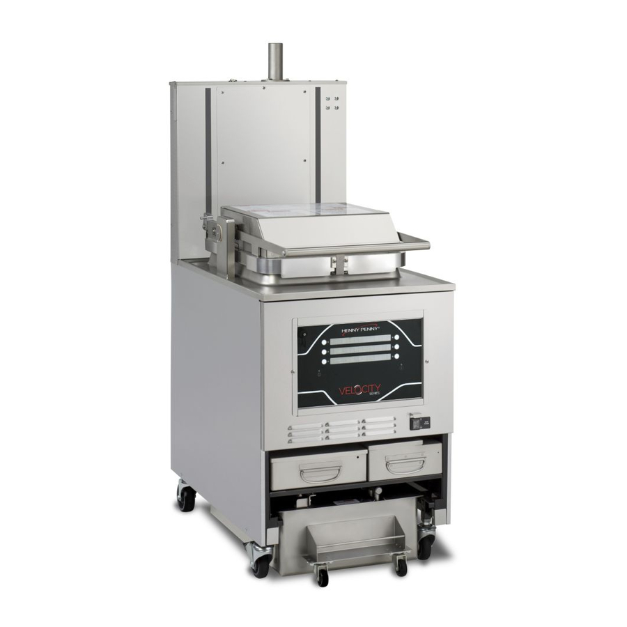
kfc pressure fryer
Hide thumbs
Also See for Velocity OXE-100:
- Service manual (134 pages) ,
- Operation manual (100 pages) ,
- Kit instructions (21 pages)

Related Manuals for Henny Penny Velocity OXE-100


Summary of Contents for Henny Penny Velocity OXE-100
- Page 1 OPERATION MANUAL V V e e l l o o c c i i t t y y S S e e r r i i e e s s ™ ™ K K F F C C P P r r e e s s s s u u r r e e F F r r y y e e r r OXE-100 FM05-099F...
-
Page 3: Table Of Contents
Table of Contents Safety and Compliance ........................ix Chapter 1 Overview ..........................1 1.1 Technical Support ..........................1 1.2 Dimensions and Clearance ......................1 1.3 Operating Specifications .........................2 1.4 Data Plate Location ........................2 Chapter 2 Unpacking and Installation .......................3 2.1 Unpacking the Appliance ........................3 2.1.1 Unloading the Appliance......................4 2.1.2 Installing Counterweights......................4 2.1.3 Finish Unpacking the Appliance ....................5... - Page 4 Chapter 6 Cooking ..........................27 6.1 Start-up ............................27 6.2 Heating Times..........................27 6.3 Lid Operation ..........................28 6.3.1 Closing the Lid ........................28 6.3.2 Opening the Lid ........................28 6.4 Product Racking Recommendations ....................28 6.5 Open Frying..........................30 6.6 Quick Filtering..........................30 6.7 Auto Top Off (ATO) ........................31 6.8 Automix............................31 Chapter 7 Maintenance .........................33 7.1 Regular Maintenance Schedule.....................33...
- Page 5 7.7.6 Perform the Heated Clean-Out ....................45 7.7.7 Drain the Water........................46 7.7.8 Rinse the Vat With Clean Water....................46 7.7.9 Purge the Oil Lines.........................47 7.7.10 Wipe the Vat ........................47 7.7.11 Exit Confirmation ........................47 Chapter 8 Programming ........................49 8.1 Program Menu ..........................49 8.2 Product Programming Menu ......................49 8.3 Product Programming Mode ......................52 8.3.1 Copy Menu Items........................52 8.4 Info Mode Menu Overview ......................53...
- Page 6 10.3.4 ZigBee Radio Info Display.....................93 10.3.4.1 Access the Display ......................93 10.3.4.2 JOIN Screen ........................94 10.3.4.3 CHANNEL Screen ......................94 10.3.4.4 PAN ID Screen .........................95 10.3.4.5 RADIO SHORT ID Screen....................95 10.3.4.6 Reset / Unjoin Command ....................96 10.3.4.7 Modbus Packet Statistics ....................97 10.3.4.8 Modbus Character RX/TX Statistics ...................97 Chapter 11 Annual Inspection Checklist Form ..................99 11.1 Required Tools .........................
- Page 8 List of Tables Table 1-1 Dimensions and Clearance ......................1 Table 1-2 Operation Specifications......................2 Table 6-1 Temperature and Timing ......................27 Table 6-2 Product Racking Recommendations...................29 Table 7-1 Regular Maintenance Schedule ....................33 Table 8-1 Info Mode Menu Function ......................54 Table 8-2 Special Program Menu Function ....................58 Table 8-3 Filter Settings ...........................61 Table 9-1 Troubleshooting Guide ......................73 Table 9-2 Error Codes..........................74...
- Page 9 Figure 10-27 Screen 6 ..........................97 Figure 10-28 Screen 7 ..........................98...
- Page 10 viii...
- Page 11 S S a a f f e e t t y y a a n n d d C C o o m m p p l l i i a a n n c c e e Henny Penny fryers have many safety features incorporated. However, the only way to ensure safe operation is to fully understand the proper installation, operation, and maintenance procedures.
- Page 12 These are the original version controlled Henny Penny instructions for Velocity Open Electric (OXE) model 100 (OXE 100). This manual is available on the Henny Penny Public website (www. hennypenny.com). Read these instructions completely prior to installation and operation of this appliance to ensure compliance to all required installation, operation and safety standards.
-
Page 13: Table 1-1 Dimensions And Clearance
1 1 . . 1 1 T T e e c c h h n n i i c c a a l l S S u u p p p p o o r r t t Call your local service provider or distributor first. For additional help, call or e-mail Henny Penny (HP) Technical Support at: •... -
Page 14: Table 1-2 Operation Specifications
1 1 . . 3 3 O O p p e e r r a a t t i i n n g g S S p p e e c c i i f f i i c c a a t t i i o o n n s s Review the information below to become familiar with the appliance operation. - Page 15 C C h h a a p p t t e e r r 2 2 U U n n p p a a c c k k i i n n g g a a n n d d I I n n s s t t a a l l l l a a t t i i o o n n This chapter outlines the unpacking and installation requirements.
- Page 16 2 2 . . 1 1 . . 1 1 U U n n l l o o a a d d i i n n g g t t h h e e A A p p p p l l i i a a n n c c e e Carefully remove the appliance from the shipping pallet.
- Page 17 2 2 . . 1 1 . . 3 3 F F i i n n i i s s h h U U n n p p a a c c k k i i n n g g t t h h e e A A p p p p l l i i a a n n c c e e 1 1 .
- Page 18 Ventilation must conform to local, state, and national codes. Consult your local NOTICE : fire department or building authorities. 2 2 . . 5 5 E E l l e e c c t t r r i i c c a a l l R R e e q q u u i i r r e e m m e e n n t t s s T T h h i i s s f f r r y y e e r r m m u u s s t t b b e e a a d d e e q q u u a a t t e e l l y y a a n n d d s s a a f f e e l l y y g g r r o o u u n n d d e e d d ( ( e e a a r r t t h h e e d d ) ) o o r r e e l l e e c c t t r r i i c c a a l l s s h h o o c c k k m m a a y y r r e e s s u u l l t t .
- Page 19 F F o o r r e e q q u u i i p p m m e e n n t t w w i i t t h h C C E E m m a a r r k k o o n n l l y y ; ; t t o o p p r r e e v v e e n n t t e e l l e e c c t t r r i i c c s s h h o o c c k k h h a a z z a a r r d d t t h h i i s s a a p p p p l l i i a a n n c c e e m m u u s s t t b b e e b b o o n n d d e e d d t t o o o o t t h h e e r r a a p p p p l l i i a a n n c c e e s s o o r r t t o o u u c c h h a a b b l l e e m m e e t t a a l l s s u u r r f f a a c c e e s s i i n n c c l l o o s s e e p p r r o o x x i i m m i i t t y y t t o o t t h h i i s s a a p p p p l l i i a a n n c c e e w w i i t t h h a a n n e e q q u u i i p p o o t t e e n n t t i i a a l l b b o o n n d d i i n n g g c c o o n n d d u u c c t t o o r r .
- Page 21 C C h h a a p p t t e e r r 3 3 I I n n i i t t i i a a l l S S t t a a r r t t u u p p 3 3 .
- Page 22 3 3 . . 2 2 D D r r a a i i n n P P a a n n A A s s s s e e m m b b l l y y Use these steps after disassembling and cleaning the drain pan, to install a new filter and reassemble the filtration system and pan assembly.
- Page 23 3 3 . . 3 3 I I n n i i t t i i a a l l O O i i l l F F i i l l l l 3.3.1 Purge the Oil Lines , page Read all warnings and then proceed to F F a a i i l l u u r r e e t t o o f f o o l l l l o o w w t t h h e e s s e e i i n n s s t t r r u u c c t t i i o o n n s s m m a a y y r r e e s s u u l l t t i i n n o o i i l l o o v v e e r r f f l l o o w w i i n n g g t t h h e e f f r r y y p p o o t t w w h h i i c c h h c c o o u u l l d d c c a a u u s s e e s s e e r r i i o o u u s s b b u u r r n n s s , , p p e e r r s s o o n n a a l l i i n n j j u u r r y y , , f f i i r r e e a a n n d d / / o o r r...
- Page 24 3 3 . . 3 3 . . 2 2 M M a a n n u u a a l l l l y y F F i i l l l l t t h h e e V V a a t t The vat has 2 level indicator lines inscribed on the rear wall.
- Page 25 3 3 . . 4 4 F F i i l l l l t t h h e e F F r r e e s s h h O O i i l l T T a a n n k k The fresh oil tank automatically tops off the oil in the vat when it senses the vat’s oil level is low.
-
Page 27: Figure 4-1 Kfc
C C h h a a p p t t e e r r 4 4 O O p p e e r r a a t t i i o o n n 4 4 . . 1 1 O O p p e e r r a a t t i i n n g g C C o o m m p p o o n n e e n n t t s s This section lists the major components of the fryer. - Page 28 Item No. Description Function Fresh Oil Tank Filled with new oil, the appliance pulls fresh oil from this reser- voir when the low oil sensor detects additional oil is needed. Never over fill the reservoir or vat. Control Panel (Board) Used to program, control and operate the appliance.
-
Page 29: Figure 4-2 Kfc
4 4 . . 2 2 C C o o n n t t r r o o l l s s a a n n d d I I n n d d i i c c a a t t o o r r s s This section provides an overview of the control board. - Page 30 4 4 . . 3 3 A A c c t t i i o o n n B B u u t t t t o o n n s s The functions of the action buttons can vary based on the nature of the currently displayed setting: •...
- Page 31 4 4 . . 6 6 M M e e n n u u S S t t r r u u c c t t u u r r e e This section provides a high level visual overview of the menu structure.
- Page 32 4 4 . . 7 7 D D i i s s p p l l a a y y O O p p t t i i o o n n s s 8.5 Special Programming , page 57 To change the display option see and the Chapter 8...
- Page 33 • Heat - The controls are designed to make frying product the most efficient process as possible. Following best practices when using the Henny Penny fryer ensures the longest oil life possible. One best practice is selecting a product menu and placing the fryer in Cool Mode when not in use.
- Page 34 • T T h h e e o o i i l l m m a a y y b b e e s s t t i i r r r r e e d d o o n n l l y y d d u u r r i i n n g g t t h h e e m m o o r r n n i i n n g g s s t t a a r r t t u u p p p p r r o o c c e e d d u u r r e e . . D D o o n n o o t t s s t t i i r r t t h h e e o o i i l l a a t t a a n n y y o o t t h h e e r r t t i i m m e e .
- Page 35 M M e e n n u u ( ( s s c c r r e e e e n n ) ) 1 1 M M e e n n u u ( ( s s c c r r e e e e n n ) ) 2 2 M M e e n n u u ( ( s s c c r r e e e e n n ) ) 3 3 M M e e n n u u ( ( s s c c r r e e e e n n ) ) 4 4 5 5 .
- Page 36 1 1 . . Select 2. DAILY. A confirm prompt displays. If the operator selects: • NO x, the display returns to the previous menu. • √ YES, the drain opens automatically and the oil begins draining. As the oil drains a brush symbol displays. Then three prompts display: FILL, WASH, DRAIN.
- Page 37 1 1 . . Press 3. POLISH. A confirm prompt displays. If the operator selects: • NO x, the display returns to the previous menu. • √ YES, the drain opens automatically and the oil begins draining. Downward pointing arrows display indicating the vat is draining.
-
Page 39: Table 6-1 Temperature And Timing
C C h h a a p p t t e e r r 6 6 C C o o o o k k i i n n g g 6 6 . . 1 1 S S t t a a r r t t - - u u p p If the oil is below 180°... - Page 40 6 6 . . 3 3 L L i i d d O O p p e e r r a a t t i i o o n n U U s s e e P P P P E E a a n n d d t t h h e e c c a a r r r r i i e e r r h h a a n n d d l l e e t t o o l l o o w w e e r r a a n n d d r r a a i i s s e e t t h h e e m m u u l l t t i i - - t t r r a a y y r r a a c c k k a a s s s s e e m m b b l l y y a a n n d d p p r r o o d d u u c c t t i i n n t t o o t t h h e e o o i i l l .
-
Page 41: Table 6-2 Product Racking Recommendations
avoided on small loads because of insufficient oil coverage. With bigger loads, the top rack has good oil coverage because the volume of product on the lower racks raises the overall oil level. T T a a b b l l e e 6 6 - - 2 2 P P r r o o d d u u c c t t R R a a c c k k i i n n g g R R e e c c o o m m m m e e n n d d a a t t i i o o n n s s G G e e n n e e r r a a l l M M a a r r k k e e t t 2 2 H H e e a a d d B B a a g g s s •... - Page 42 6 6 . . 5 5 O O p p e e n n F F r r y y i i n n g g Follow the procedure below to complete a cook cycle. D D o o n n o o t t o o v v e e r r l l o o a a d d t t h h e e r r a a c c k k s s w w i i t t h h p p r r o o d d u u c c t t ( ( 2 2 4 4 l l b b s s . . ( ( 1 1 0 0 . . 9 9 k k g g ) ) m m a a x x i i m m u u m m ) ) , , o o r r p p l l a a c c e e p p r r o o d d u u c c t t w w i i t t h h e e x x t t r r e e m m e e m m o o i i s s t t u u r r e e c c o o n n t t e e n n t t i i n n t t o o r r a a c c k k s s .
- Page 43 6 6 . . 7 7 A A u u t t o o T T o o p p O O f f f f ( ( A A T T O O ) ) I I N N F F O O : Not used in bulk fill applications. The fryer is equipped with an automatic top off feature that keeps the oil level in the vat within the operating limits.
-
Page 45: Table 7-1 Regular Maintenance Schedule
C C h h a a p p t t e e r r 7 7 M M a a i i n n t t e e n n a a n n c c e e The following cleaning procedures ensures the fryer is sanitary while keeping product quality high and downtime to a minimum. - Page 46 • Clean the drain pan and replace the filter. 7 7 . . 3 3 . . 1 1 D D a a i i l l y y F F i i l l t t e e r r A daily filtering of the oil is essential to prolong the life of the oil and the unit.
- Page 47 7 7 . . 4 4 C C l l e e a a n n t t h h e e C C a a s s t t o o r r W W h h e e e e l l s s - - W W e e e e k k l l y y Spray Henny Penny biodegradable, food safe, foaming degreaser (part no.12226) on castor wheels at least once a week as part of the normal cleaning routine.
- Page 48 7 7 . . 6 6 O O i i l l D D i i s s p p o o s s a a l l Oil disposal is unique to each fryer. Three unique oil disposal types are available; manual, rear or front disposal.
- Page 49 Never pour oil down a public NOTICE : sanitation drain. Henny Penny recommends using an automated bulk oil disposal system, or a manually operated Oil Disposal Shuttle (ODS) to drain degraded oil from the vat and transport it to an approved oil disposal storage container.
- Page 50 7 7 . . 6 6 . . 2 2 . . 2 2 D D r r a a i i n n t t h h e e O O i i l l Using an Oil Disposal Shuttle (ODS) drain the oil from the vat by doing the following: U U s s e e P P P P E E .
- Page 51 7 7 . . 6 6 . . 2 2 . . 5 5 F F i i l l l l t t h h e e V V a a t t w w i i t t h h O O i i l l Fill the vat with new oil by doing the following: Press the n n e e x x t t ►...
-
Page 52: Manually Fill The Vat
7 7 . . 6 6 . . 3 3 . . 3 3 P P u u r r g g e e t t h h e e F F i i t t t t i i n n g g s s Degraded oil remains inside the lines, valves and fittings. -
Page 53: Chapter 4 Operation
Remove, clean and dry the drain pan and install a new filter. Refer to 3.2 Drain Pan Assembly , 3 3 ) ) page 10 for instructions. Insert the drain pan under the unit until it latches. 4 4 ) ) Press the A A d d d d <... - Page 54 7 7 . . 6 6 . . 4 4 . . 4 4 P P u u r r g g e e t t h h e e F F i i t t t t i i n n g g s s Degraded oil remains inside the lines, valves and fittings.
- Page 55 Insert the drain pan under the unit until it latches. 4 4 ) ) Manually fill the vat, by pouring oil from a container, to the lower limit line with new oil. 5 5 ) ) Power on the unit and return to normal operation. 6 6 ) ) 7 7 .
-
Page 56: Main Menu
D D o o n n o o t t c c l l o o s s e e l l i i d d w w i i t t h h w w a a t t e e r r a a n n d d / / o o r r c c l l e e a a n n e e r r i i n n v v a a t t . . W W a a t t e e r r u u n n d d e e r r p p r r e e s s s s u u r r e e b b e e c c o o m m e e s s s s u u p p e e r r h h e e a a t t e e d d . - Page 57 Press and hold the M M a a i i n n menu button until *MAIN* displays. The Main menu displays. 2 2 ) ) Press the 1 1 . . F F I I L L T T E E R R button. Additional menu items display. 3 3 ) ) Press the M M a a i i n n menu button twice.
- Page 58 Scrub the underside of the lid. 5 5 ) ) Remove and clean the lid gasket. The time on the timer runs out. =CLEAN OUT= *DONE*, and 6 6 ) ) then TURN FRYER OFF displays. Press the power off button. =DRAIN= DRAIN (hold) and next► displays. 7 7 ) ) Proceed to 7.7.7 Drain the Water , page...
- Page 59 7 7 . . 7 7 . . 9 9 P P u u r r g g e e t t h h e e O O i i l l L L i i n n e e s s Clear dirty, unusable oil, water and debris from the oil lines by doing the following: Confirm the fresh oil tank has new oil in it.
- Page 61 C C h h a a p p t t e e r r 8 8 P P r r o o g g r r a a m m m m i i n n g g 8 8 . . 1 1 P P r r o o g g r r a a m m M M e e n n u u From the MAIN menu, refer to 4.5 Main Menu , page 18, select 4.
- Page 62 5 5 . . Press the number buttons, 1 through 0, to select an option. 6 6 . . Press the “ “ ” ” button to confirm completion. 7 7 . . Press the right-arrow button. LINK ID displays. The Link ID is an abbreviation for the cook menu.
- Page 63 1 1 8 8 . . Press the number buttons to set the temperature. 1 1 9 9 . . Press the right-arrow button. ALARM 1 displays. 2 2 0 0 . . Press the number buttons to set the alarm. 2 2 1 1 .
- Page 64 3 3 0 0 . . Press the number buttons to set the temperature range for pulsed heating. Set to 0 for full heat. This is the number of degrees below setpoint during cooking at which pulsed heat is used, which can help avoid overshoots.
- Page 65 1 1 . . Select 2 2 . . C C O O P P Y Y . Copy from product number displays on the left and the copy to product number displays on the right. 2 2 . . Press the + + or - - button to select any product to copy from, and any product to copy too.
-
Page 66: Table 8-1 Info Mode Menu Function
T T a a b b l l e e 8 8 - - 1 1 I I n n f f o o M M o o d d e e M M e e n n u u F F u u n n c c t t i i o o n n Menu Item Function E-Log (Error Log... - Page 67 Menu Item Function • - - No signal present • DTF - Discard Tank Full • FULL - Discard tank is full and cannot dispose to it • OK - Discard tank not full, okay to dispose Pressure Inputs Manifold Pressure Displays pump pressure reading if optional transducer is installed in plumbing manifold •...
- Page 68 Menu Item Function Pump Outputs • * - On • - - Off • Fltr - Filter Pump • ATO - Top Off Pump • Bulk - Bulk oil Supply Analog Inputs Displays analog input readings directly from ADC chip displayed as volts and as ADC counts (bits).
- Page 69 Menu Item Function ATO (Auto-Topoff) • LVL - Levels Level – FULL – – - - - - Displays when an assessment is not possible • Delta - Displays the temperature difference between the main probe and the level probe. •...
-
Page 70: Table 8-2 Special Program Menu Function
T T a a b b l l e e 8 8 - - 2 2 S S p p e e c c i i a a l l P P r r o o g g r r a a m m M M e e n n u u F F u u n n c c t t i i o o n n Menu Display Name Function... - Page 71 Menu Display Name Function • COOK - to begin the cook cycle immediately. SP-12 COOK DONE GO Press the plus or minus button to select the default cook menu to WHERE? display after each cook cycle completes. SP-13 AUTO-MENU MINUTES Press the plus or minus button to select a time in minutes.
-
Page 72: Table 8-3 Filter Settings
Menu Display Name Function used to access modes such as Product, Cook, Special Program- ming, etc. SP-21 CHANGE USAGE Provides access to change the Reset Usage password code, CODE which is defaulted to 123 from the factory. The Reset Usage password code is used to access the usage statistics, it does not grant any programming privileges. - Page 73 T T a a b b l l e e 8 8 - - 3 3 F F i i l l t t e e r r S S e e t t t t i i n n g g s s Program Display Description...
- Page 74 Program Display Description Code I I N N F F O O : The control defaults to Global Mode filtering, with the global Filter After X Cooks parameter set to FC-1A QUICK FILTER: AFTER ‘X’ COOKS Controls automatic activation of the Quick Filter after the specified number of cook cycles.
- Page 75 Program Display Description Code the upper probe and the expected temperature rise is observed. 1 1 . . Enter a new value by using the product numbers. 2 2 . . Press “” to accept the new value. 3 3 . . Press “X” to return to default or previous setting. FC-7 QUICK FILTER: NORMAL FILL TIME The expected time it takes to refill the vat at the end...
- Page 76 Program Display Description Code FC-10 DAILY FILTER + POLISH: FILL: DE- When refilling the pot, specifies how long to keep TECT AT LEVEL PROBE, KEEP pumping after the oil reaches the upper probe and PUMPING the expected temperature rise is observed. 1 1 .
- Page 77 Program Display Description Code 3 3 . . Press “X” to return to default or previous setting. FC-14 POLISH: FILTER: TIME At the end of the Drop cycle, controls how long the fil- ter pump runs for the specified filter time. 1 1 .
- Page 78 Program Display Description Code I I N N F F O O : If X pulses of oil have not brought the level up, the control assumes that the oil tank is empty—that no oil is being pumped into the pot—and displays FILL OIL TANK. If the fryer is configured to use a Bulk Oil Sup- ply system, the message displayed is CHECK BULK OIL SUPPLY rather than FILL OIL TANK.
- Page 79 Program Display Description Code brought up to the proper level, the control beeps and displays FILL OIL TANK. 1 1 . . Enter a new value by using the product numbers. 2 2 . . Press “” to accept the new value. 3 3 .
- Page 80 Program Display Description Code FC-25 START-UP MIX: PRE-HEAT MAX The Start-up Mix procedure consists of two steps: 1. TEMP Heat up the oil to the Mix Preheat temperature and 2. Drop the oil, filter, and refill the pot. 1 1 . . Enter a new value by using the product numbers. 2 2 .
- Page 81 Filter powder should be added to the drain pan in order for the Polish operation to be most effective. FC-32 START-UP POLISH: ENABLED? Henny Penny recommends enabling the Start-up Pol- ish to prolong the life of the oil. This adds time to the Start-up process. Press the + or - button to select either YES or NO.
- Page 82 Program Display Description Code FC-35 COOK MODE AUTO MIX: DROP OIL: Controls the time duration of the draining of the pot. TIME 1 1 . . Enter a new value by using the product numbers. 2 2 . . Press “” to accept the new value. 3 3 .
- Page 83 Program Display Description Code FC-40 COOK MODE AUTO MIX: MIN RE- This is the minimum oil temperature required in order QUIRED OIL TEMP to activate an Auto Mix operation. 1 1 . . Enter a new value by using the product numbers. 2 2 .
- Page 84 Program Display Description Code FC-44 ALWAYS ASK, IS POT FILLED? This option can be engaged to always ask – at the end of each Quick Filter, Auto Mix, and Polish opera- tion, if the pot is filled. Normally, the control asks IS POT FILLED? only if it has pumped for a long time at- tempting to fill the pot, but no temperature rise was observed on the upper temperature probe.
-
Page 85: Table 9-1 Troubleshooting Guide
C C h h a a p p t t e e r r 9 9 T T r r o o u u b b l l e e s s h h o o o o t t i i n n g g 9 9 . -
Page 86: Table 9-2 Error Codes
9 9 . . 3 3 E E r r r r o o r r C C o o d d e e s s In the event of a system failure the control board displays an error message. These messages are coded as E which represents an error, a number designation and error message, such as E-4 CPU TO HOT. - Page 87 Error Cause Correction E-15P DRAIN The drain valve doesn’t Check drain for an obstruction. If the error persists call for VALVE fully open. service. ERROR E-18A LEVEL The oil level probe has Call for service. SENSOR failed. FAILED (Open Circuit) E-18B LEVEL SENSOR FAILED...
- Page 88 Error Cause Correction E-47 ANA- Problem reading the A- Call for service. LOG SYS- to-D Analog to Digital TEM OR 12 converter inputs. VOLT FAILED Failure of the CPU Call for service. E-48 INPUT SYSTEM board. ERROR E-54C MAIN Fault on the CPU board. Call for service.
-
Page 89: Chapter 6 Cooking
The Velocity control board communicates directly with the Digi radio module. The radio modules are manufactured by Digi with firmware customized for Henny Penny, to support operator requirements. The radio module speaks the standard ZigBee protocol on the wireless side, and speaks RS-485 Modbus protocol on the hard-wired side to communicate with the fryer’s control board. - Page 90 (over the Internet) server which contains the Operator’s Smart Kitchen software. The upside is the signal from the Henny Penny fryer has many additional opportunities to reach the server successfully. The downside is if our signal is blocked by a structure (i.e. wall, distance, etc.) and is using another appliance (node) to reach the server, then we have an additional point of failure.
-
Page 91: Figure 10-1 Connecting Wires To Terminal Block
1 1 0 0 . . 2 2 . . 1 1 I I n n s s t t a a l l l l t t h h e e H H a a r r d d w w a a r r e e On a table or countertop, position the radio adapter so that the terminal block screws are face- 1 1 ) ) up. -
Page 92: Figure 10-2 Sliding Radio Module On To Studs
Slide the radio on to the studs, located on the side of the control, with the green (9-pin) 3 3 ) ) connector directed towards the fryer. See Figure 10-2 Sliding Radio Module on to Studs , page Figure 10-2 Sliding Radio Module on to Studs To attach the barrel connection to the radio, align the barrel connector with the notches located 4 4 ) ) on the top of the radio. -
Page 93: Figure 10-3 Attaching Connector To Radio
Figure 10-3 Attaching Connector to Radio Using the nuts provided in the kit, secure the radio to the controls with a 1/4 inch socket or nut- 5 5 ) ) driver. See Figure 10-4 Securing Radio to Control , page Figure 10-4 Securing Radio to Control Run the wires underneath the side of the adapter, then connect the 9-pin connector to the 6 6 ) ) -
Page 94: Figure 10-5 Connecting 9-Pin Connector
Figure 10-5 Connecting 9-Pin Connector I I N N F F O O : It is recommended to gather power harness wires and tie with wire tie. See Figure 10-6 Gather Wires in Wire Tie , page Figure 10-6 Gather Wires in Wire Tie Place control board back to factory location and secure with the Phillips head screws. -
Page 95: Figure 10-7 Op Decal Location
Place the OP decal on the lower right-hand corner of the control board. See Figure 10-7 OP 8 8 ) ) Decal Location , page Figure 10-7 OP Decal Location 1 1 0 0 . . 2 2 . . 2 2 C C o o n n f f i i g g u u r r e e t t h h e e O O P P S S / / Q Q P P M M S S e e t t t t i i n n g g s s 1 1 0 0 . -
Page 96: Figure 10-8 Menu & Info Button Locations
Figure 10-8 Menu & Info Button Locations Press and release the menu button (1) again, to cycle to the second set of menu options. 2 2 ) ) Figure 10-9 Second Set of Main Menu Options Select 4.PROG. See Figure 10-9 Second Set of Main Menu Options , page 84. -
Page 97: Figure 10-10 Programming Menus
Figure 10-10 Programming Menus Select 3.SPCL PROG. See Figure 10-10 Programming Menus , page 4 4 ) ) Using the number buttons, enter code 1, 2, 3. 5 5 ) ) Use the top right arrow to navigate to SP-4 ENABLED. See Figure 10-11 SP-4 OPS/QPM 6 6 ) ) Enabled , page... -
Page 98: Figure 10-12 Sp-4 Ops/Qpm Enabled Yes Display
Figure 10-12 SP-4 OPS/QPM Enabled Yes Display Press and hold the menu button to exit special program mode. 8 8 ) ) 1 1 0 0 . . 2 2 . . 2 2 . . 3 3 V V e e r r i i f f y y C C o o m m m m u u n n i i c c a a t t i i o o n n Verify the Digi radio can communicate with the fryer’s control board and the network. -
Page 99: Figure 10-14 Channel Status Display
I I N N F F O O : These messages only indicate if the Digi radio and control board are communicating. It does not mean the Digi radio is communicating with the network. The bottom display reads JOIN = followed by a value. If the value reads 00, this means the 4 4 ) ) radio is joined to the network. -
Page 100: Figure 10-16 Radio Short Id Display
Use the down arrow to navigate to the Radio Short ID display screen. See Figure 10-16 Radio 9 9 ) ) Short ID Display , page Figure 10-16 Radio Short ID Display The bottom display reads RADIO followed by a value. If the radio is joined to a network, that 1 1 0 0 ) ) particular radio module number displays. -
Page 101: Figure 10-18 Number Buttons
1 1 0 0 . . 2 2 . . 3 3 C C o o o o k k I I D D C C o o d d e e The OPS/QPM system in the store must be configured so that it understands which products are being cooked by the Velocity fryer. -
Page 102: Figure 10-20 Unique Product Number Display
Figure 10-20 Unique Product Number Display Use the product number to identify what product is being cooked. For example, P3 represents 4 4 ) ) Product 3. 1 1 0 0 . . 2 2 . . 4 4 Z Z i i g g B B e e e e I I d d e e n n t t i i f f y y R R e e s s p p o o n n s s e e 1 1 0 0 . -
Page 103: Figure 10-21 Zigbee Id Display
When our controls and radio modules leave Henny Penny, they are sent out in an U U n n j j o o i i n n e e d d state, which means they are not a member of any particular network group. -
Page 104: Zigbee Protocol
1 1 0 0 . . 3 3 . . 2 2 . . 2 2 J J o o i i n n i i n n g g a a N N e e t t w w o o r r k k The radio must be manually invited by the OPS/QPM computer to join the store’s ZigBee network. -
Page 105: Configure The Ops/Qpm Settings
Ensure seamless data communication between the Digi radio and control board by doing the following: 1 1 0 0 . . 3 3 . . 3 3 . . 2 2 . . 1 1 C C h h e e c c k k t t h h e e W W i i r r e e s s Verify the 9-pin connector is connected correctly, and not reversed. -
Page 106: Figure 10-22 Screen 1
I I N N F F O O : Info Mode can not be used to enable or disable the OPS/QPM system. It simply provides access to the ZigBee Radio Info Display if the OPS/QPM system has already been enabled. The same information is available in Data Comm program mode, as item DC-2. -
Page 107: Figure 10-23 Screen 2
Figure 10-23 Screen 2 1 1 0 0 . . 3 3 . . 4 4 . . 4 4 P P A A N N I I D D S S c c r r e e e e n n Displays the PAN ID number (Personal Area Network ID) of the ZigBee network the radio is currently joined to. -
Page 108: Figure 10-25 Screen 4
Figure 10-25 Screen 4 1 1 0 0 . . 3 3 . . 4 4 . . 6 6 R R e e s s e e t t / / U U n n j j o o i i n n C C o o m m m m a a n n d d This option resets the radio module;... - Page 109 1 1 0 0 . . 3 3 . . 4 4 . . 7 7 M M o o d d b b u u s s P P a a c c k k e e t t S S t t a a t t i i s s t t i i c c s s Displays statistics about the data packets received from the radio module (i.e.
- Page 110 Figure 10-28 Screen 7 In our particular RS485 implementation, the control hears its own transmissions, so it can confirm that what it sent was transmitted correctly. The RX count reflects only the characters received from other devices (i.e. from the radio module). It does not include the characters the control sent.
-
Page 111: Table 11-1 Annual Inspection Checklist
C C h h a a p p t t e e r r 1 1 1 1 A A n n n n u u a a l l I I n n s s p p e e c c t t i i o o n n C C h h e e c c k k l l i i s s t t F F o o r r m m Perform the following annual inspection in the order provided. - Page 112 Verify all components of the drain pan are present and not da- maged. Components include five O-rings, filter screen, two fil- ter clips, standpipe, crumb basket, drain pan, drain pan cover and drain pan casters. Replace any components that are miss- ing or damaged.
- Page 113 gasket if it has not been replaced in the last 12 months, or if the gasket is hardened, brittle, damaged, or blackened. Inspect Lid Handle Rollers – Please read and follow all instruc- tions for this step. Inspect cam slide fillers located on each side of the lid cover. Inspect front lid latch and make adjustments as necessary.
- Page 114 • Lid gasket • Temperature probe • Spindle lube • Pipe thread sealant • Towels • Steel and teflon sleeve fittings • Condensation box hose • Check valve • Lid handle rollers • Nylatron slides • Side cam filters • Lid latch •...
- Page 117 blank page...
- Page 118 H H e e n n n n y y P P e e n n n n y y C C o o r r p p o o r r a a t t i i o o n n P P .
Need help?
Do you have a question about the Velocity OXE-100 and is the answer not in the manual?
Questions and answers