Table of Contents
Advertisement
Advertisement
Table of Contents

Subscribe to Our Youtube Channel
Related Manuals for Henny Penny OE-30X


Summary of Contents for Henny Penny OE-30X
- Page 2 Henny Penny Model OE/OG 301/302/303...
-
Page 3: Replacement Parts
Henny Penny LIMITED WARRANTY FOR HENNY PENNY APPLIANCES FM01-360 Revised 12-29-06... - Page 4 The Model OG-301/302/303 Fryers are equipped with a continuous pilot. Fryer can not be operated without electric power. Fryer will automatically return to normal operation when power is restored. proper instaIlatiom, adj...
- Page 5 Natural (I& = 2 1,l KW Nominal Heat Input: Liquid Propane (I& = 21,l KW (Net) Nominal Heat Input: Natural (I,,) = 23,4 KW (Gross) Liquid Propane (IJ = 23,4 KW Supply Pressure: Natural (IJ = 20 mbar Liquid Propane (I,,) = 37 mbar Liquid Propane (IJ = 50 mbar Test Point Pressure: Natural (I&...
- Page 6 Section Section 1. INTRODUCTION l-2. Model Variations ... Features ... l-3. l-4. Safety ... 1.5. Assistance..Section 2. INSTALLATION. 2-l. Introduction.. 2-2. Unpacking ... 2-3. Selecting the Location ... 2-4. Leveling the Fry Station ... 2-5. Ventilation of Fry Station ... 2-6.
- Page 7 Genuine Parts ... 7-2. When Ordering Parts ... 7-3. 7-4. Prices ... 7-5. Delivery ... Warranty 7-6. 7-7. Recommended Spare Parts for Distributors... Henny Penny Distributor Lists (Domestic and International) 6-10 6-12 6-14 6-15 6-18 6-19 6-20 6-21 6-22 6-25 6-27...
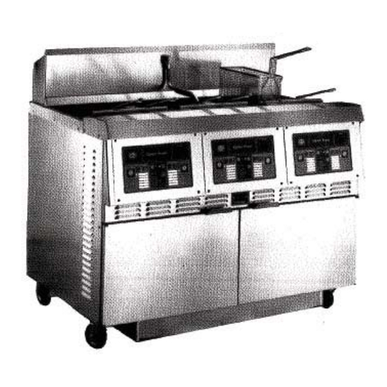
- Page 8 1-2. The Henny Penny Open Fry Station is a basic unit of food equipment designed to cook foods better and easier. The microcomputer based design helps make this possible. This manual covers the following variations of the Henny Penny Open Fry Station:...
- Page 9 The word WARNING is used to alert you to a procedure that if not performed properly, might cause personal injury. The word CAUTION is used to alert you to a procedure that, if not performed properly, may damage the fry station. The word NOTE is used to highlight especially important information.
- Page 10 Do not puncture the unit with any objects such as drills or screws as component damage or electrical shock could result. The Henny Penny Fry Station has been tested, inspected, and expertly packed to ensure arrival at its destination in the best possible condition.
- Page 11 Order assembly can be moved away with only a slight loss of efficiency. The fryer should be installed in such a way as to prevent tipping or movement causing splashing of hot liquid shortening. This may be accomplished by the location the fiy station is in, or by restraining ties.
-
Page 12: Gas Supply
The OG-301 can be operated at altitudes of up to 4000 feet above sea level with no changes to the unit. For operation above 4000 feet, please contact Henny Penny Corporation for changes to the unit. Do not attempt to use any gas other than that specified on the data plate. - Page 13 INIMU~I PULL of equip- AVOID SHARP BENDS AND KINKS when ment away from wall pulling equipment permissible for accessi- imum pull will kink ends, even if installed bility to Quick Disconnect properly, Device. Couplings and hose should be installed same plane as shown at left.
- Page 14 Refer to the cable restraint instructions (illustration 2-6) on how and where to attach the restraining devices to the wall and fryer. Prior to turning the gas supply on, be sure the gas dial cock on fry station gas valve is in the OFF position.
- Page 15 The following steps provide the pilot PROCEDURE lighting procedure: 1. Open doors and open gas shut-off valve. (see illustrations) 2. The gas cock dial has a dual function: a. Complete control of gas to the pilot and main burner. b. When in the pilot position, it is the reset mechanism for the automatic pilot.
- Page 16 Depress lightly and turn manual lever on gas valve to the OFF position. The gas pressure regulator on the automatic gas valve is factory set as follows: @ Natural: 3.5 inches water column. Propane 10 0 inches water column. 120 V, 50/60 Hz., 12 A, 1 PH 0 230 V, 50/60 HZ., 6 A, 1 PH The gas fry station requires a 3 wire grounded service.
- Page 17 The OE-301/302/303 is available from the factory wired 208, or 220/240 volts, 50 or 60 hertz source. Refer to the table below for supply wiring and fusing. Volts Phase 220/240 2201240 This fry station must be adequately and safely grounded. Refer to local electrical codes for correct grounding procedures.
- Page 18 Function This two position rocker type switch controls the power to the fryer when in the on position. The digital display is to show the shortening temperature, as well as the timer countdown in the frying cycle. The temperature...
- Page 19 Melt LED When the melt LED is flashing, the fryer is in the melt cycle. When the temperature of the shortening reaches approximately 250°F (121”C), the melt LED will go off and automatically switch to the heat cycle. When using solid shortening, it is recommended to melt the shortening on an outside heating source before placing shorten- ing in the cookpots.
- Page 20 tern escriptiori Other LED Idle LED Up and Down Switches Fuses (electric only) High Limit Reset Contactors (electric only) Thermal Sensor &I -;j The other LED flashes while in the high level program mode and special program modes only. Several parameters can be pro- grammed at this time.
- Page 21 Drain Interlock (Hidden behind bracket) Drain Valve Filter Union The drain interlock switch is a microswitch that provides pro- tection for the heating elements in the event an operator drains shortening from the frypot while the power switch is on. The drain switch is designed to automatically shut off the control system when the drain valve is opened.
- Page 22 Fig. Filter Drain Pan Filter Pump Switch Oil Return Line Gas Shut-Off Valve (gas only) Gas Control Valve (gas only) Gas Solenoid (gas only) Function The .removable filter drain pan houses the filter and catches the shortening when it is drained from the frypot. It is not to be used to remove and discard the shortening when the shorten- ing needs replaced.
- Page 23 el 0...
- Page 25 re 3-...
- Page 26 ode!
- Page 27 Main Power Switch The main power switch is a two,way switch. Move the switch to the position marked ON to operate the fryer. Move the switch to the position marked ON to operate the The thermostat is an electro-mechanical device used to below the temperature set by the thermostat.
- Page 28 It is recommended that a high quality frying shortening be used in the O&301/302/303 and OG-301/302/303 fry stations. Some low grade shortenings have a high moisture content causing foaming and boiling over. The Henny Penny OE-301/302/303 requires 48 pounds of shortening per cookpot. The OG-301/302/303 requires 43 pounds per cookpot.
- Page 29 ove power switch to the “ON” automatically go into the melt cycle. When the temperature reaches 250°F (121OC) the control will go into the heat cycle. The shortening will be heated until the temperature setting is reached. The melt cycle may be bypassed, if desired, by pressing the Exit Melt switch and holding it for five seconds.
- Page 30 Frying breaded food requires frequent filtering. Taste the cold shortening every day for flavor. Watch the shortening for foaming during the frying cycle. Discard the shorten- ing as soon as it shows sign of foaming. Clean the cookpot as follows each time the shortening is changed or filtered. 1.
-
Page 31: Filter Pump Problems
enny 3-5. (~o~ti~ue~) If shortening is slow coming from faucet, it is possible that the filter connecting the union on the filter tube line is not tightened properly. If so, turn off the pump and use gloves to tighten the union. This union will be hot. Severe burns could result. - Page 32 The filter pump motor is equipped with a manual reset but- ton in the event the motor’s thermal protector acuates. This reset button is located on the rear of the motor. Wait ap- proximately 5 minutes before attempting to reset this pro- tector device.
- Page 33 14. Place complete filter screen assembly back into filter drain pan, replace cover, and slide pan back into place beneath the fryer. 15. Connect the filter union by hand. Do not use a wrench to tighten. 16. The fryer is now ready to operate. dry before...
-
Page 34: Cleaning The Cookpots
After the initial installation of the fryer, as well as .before every change of shortening, thoroughly cleaned as follows: Melt bypass should be in operation. Refer to section 3-2 “Operating Controls” on Exit Melt Switch. 1. Turn the main power switch OFF. - Page 35 7. Let the cleaning solutions stand for 15 to 20 minutes with the power off. 8. Using the fryer brush (never use steel wool), scrub the inside of the cookpot. 9. After cleaning, open the drain valve and drain cleaning solution from the cookpot into the drain pan and discard.
- Page 36 The controls have four programming levels, a first level mode, a second level mode, a third level mode, and a special program mode. In each level, pressing the set switch advances through the programmable items. Program mode can be entered at anytime except during an alarm.
- Page 37 7. Press the set switch and the alarm LED flashes. The left display shows “AL 1”) the right display shows the alarm time and can be adjusted with the right Up and Down Switches. 8. Repeat step 8 for alarms 2,3, and 4. 9.
- Page 38 4-3. I 8. Also, with the Product LED flashing, pressing the right Up and Down Switches will access the Idle Mode parameters. The idle LED will be flashing, the left display will continue to show “Slct” and the right display shows “Prod.”...
- Page 39 3. Press the Set Switch and the left display flashes “Prob” and “Calib.” The right display shows the actual pot temperature, and the right Up and Down Switches are used for calibration. 4. Press the Set Switch and the left display flashes “AL” and “dur.”...
- Page 40 This section provides troubleshooting information in the form of an easy-to-read table. If a problem occurs during the first operation of a new fryer, recheck the installation per Section 2 of this manual. Before troubleshooting, always recheck the operating procedure per Section 3 of this manual.
- Page 41 Open Circuit With switch in POWER position and switch light not illuminated, fryer is complete ly inoperative. No power to With switch in power position, board switch light is on, but all other lights are out ex cept the pump will operate.
- Page 42 Replace therm0 couple per Section 6-10. Service per Section 6-11. Close drain valve. With power removed from fryer, check across high limit switch terminals with ohmmeter. Replace if no reading is indicated on meter. With power removed from fryer, check across electrical leads of gas control valve with ohmmeter, and gas valve in “ON”...
- Page 43 5-2. T (Continued) Low or improper Heating of shortening too voltage (elec. slow model) Weak or burnt out elements (elec. model) Heating of Points in contac- tor bad (elec. shortening too slow (elec. model model) Wire(s) loose Burnt or charred wire connection Supply line too small - low gas...
- Page 44 Water in ing over of shortening shortening. Improper or bad shortening Improper filtering Improper rinsing after cleaning the fryer Drain valve Shortening will not drain from clogged with frypot crumbs Drain valve will not open by turn- ing handle Filter motor rum...
- Page 46 (1). A continuity light cannot be used to check coils or motors. To replace parts located inside the fryer, the control panel must be removed, or hinged down. 1. Place the power switch in the OFF position and remove power supplied to the unit, or on electric models, to the cookpot to be worked on.
- Page 47 6-3. (~~~ti~~ed) 2. Using a Phillips head screwdriver, remove the four screws securing the control panel to the unit, and let panel swing down. The panel is hinged to hang in this position for convenience. 3. Disconnect nine-pin connector and remove probe connec- tion from control panel.
- Page 48 Disconnect power supplied to the unit by unplugging the power cord, or turning off the wall circuit breaker, or fuse. Be aware that the other controls will HAVE power on electric models, or electrical shock could result. 2. Swing control panel down per section 6-3. 3.
- Page 49 6-5. This high temperature control is a manual reset control which senses the temperature of the shortening. If the shortening temperature exceeds the safe operating limit, this control switch will open and shut off the heat to the frypot. When the temperature of the shortening drops to the safe operating limit, the control must manually be reset.
- Page 50 Before following these steps, place POWER switch to the OFF position, and unplug the power cord or open the wall circuit breaker, or electrical shock could result. Be aware that the other controls will HAVE power. 1. If the tube is broken or cracked, the control will open, shut- ting off electrical power.
- Page 51 6-5. Be sure capillary bulb of high limit is located behind front edge of elements. Capillary bulb and bulb holders should be posi- tioned as not to interfere with basket or when cleaning the frypot wall, or damage to capillary tube could result. 15.
- Page 52 5. Remove probe as described in section 6-4. 6. Loosen small inside screw nut on capillary tube. 7. Remove capillary bulb from bulb holder on inside of frypot. 8. Remove larger outside screw nut that threads into “Y” fitting. 9. Cut the capillary bulb on the inside of cookpot, and remove the capillary from unit.
- Page 53 Heating elements are available for 208 and 230 voltage. Check data plate to determine the correct voltage. If the shortening’s temperature recovery is very slow or at a slower rate than required, this may indicate defective heating element(s). An ohmmeter will quickly indicate if the elements are shorted or open.
- Page 54 enny 7. Remove the heating elements from the frypot as a group by lifting the far end and sliding them up and out toward the rear of the frypot. Always install new rubber 0 rings (2) when installing heater elements. 8.
- Page 55 ELS) PRIMARY CONTACTOR Each electric fryer requires two switching contactors. One is the primary contactor and the second in line is the heat con- tactor. When open, the primary contactor allows no power to flow to the heat contactor. When closed, the primary eontac- tor completes the timer circuit and the high limit (heat) cir- cuit.
- Page 56 The following checks are performed with the wall cir- cuit breaker closed and the main power switch in the “ON” position. Extreme caution should be taken. Make connections before applying power, take reading, and remove power before removing meter leads, or elec- trical shock could result.
- Page 57 4. Connect the labeled wires to their respective positions. 5. Install the control panel per section 6-3. 6. Reconnect power to the fryer and test the fryer for proper operation. The gas model fryers have gas burner assemblies per cookpot consisting of Burner Casting, Orifices, Thermocouples, Pilot Holders, Main Gas Valve Controls, and Gas Safety Solenoid.
- Page 58 8. Remove two screws from gas valve heat shield. 9. Remove entire gas burner assembly, by lifting and pull- ing toward front of fryer. a. Replace thermocouple as required per section 6-10. b. Repair or replace gas valve as required per section 6-11.
- Page 59 When the pilot is lit, the flame must surround the top of the thermocouple. 4. Turn on the main gas supply and reconnect the electrical power. 5. Light the pilot per paragraph 2-11 and test the fryer for proper operation. is accomplished with the...
- Page 60 - OFF/PILOT/ON. The components of the gas valve can be serviced without removing the complete valve from the fryer. If converting from natural gas to propane gas or from propane gas to natural gas, conversion must be done by a qualified technician.
- Page 61 4. Remove the 90° connector and conduit from the old gas valve and install on the replacement gas valve. 5. Remove the four screws securing the operator and gasket. 6. Secure the new operator and gasket with the four screws provided.
- Page 62 PILOT THERMOCOUPLE The following two procedures must be performed with the gas supply reconnected and turned on. The service cord must be plugged into the receptacle and the cir- cuit breaker on. 1. The pilot burner is preset at the factory. It may require resetting at the time of installation.
- Page 63 The electric fryers have two 15 amp fuses to protect the cir- cuitry, and two 15 amp fuse to protect the PC board, for each control panel, found behind doors, up under shroud. The gas units do not have fuses other than at the main power source. Each PC board has a 1.5 amp fuse as a surge protec- tor.
- Page 64 All-model fryers have a drain microswitch in line with the gas valve or heat contactor. When the drain valve is opened to drain the shortening, this causes the drain switch to open, shut- ting down the gas to the burners or electrical power to elements.
- Page 65 The Power Switch is a two way rocker switch. With the switch in the “ON” position, this energizes the controls. 1. Remove power supplied to the unit, or on electric models, to the cookpot to be worked on. Disconnect power supplied to the unit by unplugging the power cord, or turning off the wall circuit breaker or fuse.
- Page 66 The filter switch is a two way rocker switch with the switch in the “ON” position, the filter motor energizes to pump up the shortening from the drain pan. 1. Remove power supplied to the unit, or on electric models, to the far right cookpot that powers the filter switch.
- Page 67 The filtering system consists of the motor and filter pump assembly, filter screen assembly, and tubing. The two most common causes for a fryer’s inability to pump shortening is that the pump is clogged with breading or solid shortening has cooled and solidified in the lines and pump.
- Page 68 INLET and OUTLET parts. Installation of the pump on the motor in any other position could cause damage to the fryer. There is an indicator on the side of the two halves of the pump, this mark must be...
- Page 69 4. To replace the pump and motor assembly, insure the main power has been removed from the fryer. Before starting this procedure move MAIN POWER SWITCH to OFF position. Disconnect main circuit breaker at the main circuit breaker box and unplug ser- vice cord from wall receptacle, or electrical shock could result.
- Page 70 Conversion must be accomplished by an authorized Henny Penny dealer or service representative, or per- sonal injury could result. GAS installation, the gas pressure regulator Never use an open flame to test for leaks. Escaping gas could cause an explosion, and personal injury or property damage could result.
- Page 71 To convert from one type of gas to another the following pro- cedure may be followed: 1. Turn the gas cock dial to the OFF position. 2. Close the main gas valve and disconnect fryer supply line. 3. Remove gas control valve and burner assembly per sec- tion 6-9.
- Page 72 318TO 112 INCH PILOT 13. Check for gas leak at the gas control valve and main gas valve per step 11 of this section, If there are no leaks, eon- tinue to step 14. If a leak is detected, shut off gas valves and repair leak. Escaping gas could cause an explosion, and personal injury and property damage could result.
- Page 74 <...
- Page 75 ode1 5 ___------------ I------- ----------1 ITRANSFORMER SWITCH PlOP9 P8 P7 P6 P5 P4 P3 P2 Pl L PANEL __----- ------- __---------- ----- CAP. /RES. 120V 50/60HZ (SEE ABOVE FOR (SEE ABOVE FOR (SEE ABOVE FOR WIRING DIAGRAM1 WIRING DIAGRAM) WIRING DIAGRAM1...
- Page 76 POWER SW I TCH...
- Page 77 TRANSFORMER 12ov POWER SWITCH SVST Pl OP9 P8 P7 P6 P5 P4 P3 P2 PI ---- _---- YI L /-h--l CAP./RES. (SEE ABOVE FOR WIRING DIAGRAM) 33724...
-
Page 78: Wiring Diagram1
---_ WIRING DIAGRAM1 THERMOSTAT FRONT CONTROL PANEL -----____-----____ ----------------- WIRING DIAGRAM) ode! 54002... - Page 79 ,__----------------------- TIMER I I I I I (SEE ABOVE FOR WIRING DIAGRAM1 THERMOSTAT FRONT CONTROL PANEL ------------------ (SEE ABOVE FOR WIRING DIAGRAM) WIRING DIAGRAM) odel ------- ‘2 c” Y I- (SEE ABOVE FOR .---- 1297...
- Page 80 I -rIMER I’ 220-240V 50/60HZ (SEE ABOVE FOR WIRING DIAGRAM) ' THERMOSTAT ‘“-‘3 IWIN i-KYtK (SEE ABOVE FOR WIRING DIAGRAM) (SEE ABOVE FOR WIRING DIAGRAM) 45389...
- Page 81 ------------------_________ SYS T 12OV 50/60HZ THERMOSTAT (SEE ABOVE FOR WIRING DIAGRAM) -----...
- Page 82 --------__ --------_-_ L--- GAS VALVE ------------ FRONT CONTROL P...-- ‘ANFI ------------ DRAIF SW I TCt IiODEL OG-300 120 VOLT, 50160HZ ode1 ----- 45325...
- Page 83 OPEN FRYER #2 OPEN FRYER rl (SEE C-45325 (SEE C-45325 WIRING DIAGRAM1 IRING DIAGRAM) ODEL OG-302 SYSTE 12OV 50/60HZ 45390...
- Page 84 - -----------------__----- ITRANSFORMER POWER SWITCH I’ L3L2 1 1 CONTROL lNPUT FRONT CONTROL PANEL 1.5------------ DRAIN nCAf./RES. SWITCH MODEL OE-300 208124OV -------- ----.
- Page 85 OPEN FRYER #l (SEE C-33282 (SEE C-33282 WIRING DIAGRAM) I I PUMP CAP./RES. ASSY OPEN FRYER #2 (SEE C-33282 WIRING DIAGRAM) WIRING DIAGRAM) 208/24OV -GND OPEN FRYER #3...
- Page 86 ^. .^ LNLJ-II OPEN FRYER #l (SEE C-33282 WIRING DIAGRAM> blUlJ I’ I ” OPEN FRYER #2 (SEE C-33282 (SEE C-33282 WIRING DIAGRAM) WIRING DIAGRAM1 208124OV I’ --I I OPEN FRYER #3...
- Page 87 CAP. /RES. OPEN FRYER #2 OPEN FRYER s3 ASSY (SEE C-33282 (SEE C-33282 WIRING DIAGRAM) WIRING DIAGRAM) 208/24OV...
- Page 88 PUMP OPEN FRYER #l OPEN FRYER #2 (SEE C-33282 (SEE C-33282 WIRING DIAGRAM) WIRING DIAGRAM1 208/24OV...
- Page 89 -----m-----m ~ANSFORMER ,110 POWER SW I TCH HEAT OUTPUT ODEL OE-300 480V 3PH...
-
Page 90: Front Control Panel
----- POWER- SWITCH L7 L2 ,, I ‘. “.UJ lTRANSFORMER FRONT CONTROL PANEL DISPLAY BOARD... - Page 91 OPEN FRYER #I OPEN FRYER #I (SEE C-33284 (SEE C-33284 IRING DIAGRAM) IRING DIAGRAM) OPEN FRYER #2 (SEE C-33284 WIRING DIAGRAM) OPEN FRYER #3 (SEE C-33284 WIRhVG DIAGRAM1...
- Page 92 400 VOLT, 3 PHASE 3N’X MOTOR JWCTlON BOX 33558...
- Page 93 OE-302 iAi2Y III1 400 VOLT, 3 PHASE 3NZ, 33559...
- Page 94 12ov POWER SW I TCH --------w---m-- rnulv IrUN I KUL V’HNtL ------------_ +------GND 208124OV 3PH L2 L2 Ll Ll 33726...
- Page 95 _-------- _-------s-w TIMER __---------w-w THERMOST FRONT CONTROL PANEL __------w-e ---s-o 1 DRAlN(;_b( 208/24OV 45324...
- Page 96 I I I OPEN FRYER #1 OPEN FRYER #2 OPEN FRYER #3 C-45324 (SEE C-45324 (SEE C-45324 ING DIAGRAM) WIRING DIAGRAM) WIRING DIAGRAM) OE-303 SYSTE 208/24OV 5372...
- Page 97 PUMP OPEN FRYER #2 OPEN FRYER #3 (SEE C-45324 (SEE C-45324 WIRING DIAGRAM) WIRING DIAGRAM) ODEL OE-302 SYSSE 208/24OV 45377...
- Page 98 OPEN FRYER ~rl (SEE C-45324 WIRING DIAGRAM1 PUMP OPEN FRYER 792 (SEE C-45324 WIRING DIAGRAM1 OE-300 SYST 208/24OV OPEN FRYER x3 (SEE C-45324 WIRING DIAGRAM1...
- Page 99 OPEN FRYER #l OPEN FRYER #l (SEE C-45324 (SEE C-45324 WIRING WIRING DIAGRAM1 DIAGRAM1 EL OE-302 OPEN FRYER #2 (SEE C-45324 WIRING SYSTE 208/24OV DIAGRAM)
- Page 100 ---_ PUMP SWITCH__ 2081’24OV 3PH THERMOSTAT POWER ---, SWITCH ONT CONTROL PANEL ------------ FRYER CONTROL CSEE ABOVE FOR WIRING DIAGRAM1 .--- 4Wl9...
- Page 101 I I I / - - - THERMOSTAT FRONT CONTROL PANEL ----------------- MODEL OE-300 480V 3PH...
- Page 102 PUMP &SWITCH CAP/RES ASSY OPEN FRYER (SEE C-45373 IRING DIAGRAM1 OPEN FRYER #2 (SEE C-45373 WIRING DIAGRAM1 480V OPEN FRYER #3 (SEE C-45373 WIRING DIAGRAM>...
- Page 103 _______------------------------------------------- OE-303 VOLT 50160 3 PHASE 3N /L PUMP MOTOR...
- Page 104 OE-302 VOLT 50160 3 PHASE 3NZ, f TIMER .._ , PUMP MOTOR 45376...
- Page 105 ---_----------_---------------- TRANSFORMER TERM I NAL CONTROL BOARD PflOE INPUT PUMP MOTOR...
- Page 106 OPEN FRYER OPEN FRYER OPEN FRYER #3 (SEE C-33601 (SEE C-33601 (SEE C-33601 IRING DIAGRA IRING DIAGRAM) WIRING DIAGRAM1 480V 3PH...
- Page 107 PUMP OPEN FRYER #1 OPEN FRYER i4r2 (SEE C-33601 C-33601 ING DIAGRAM) WIRING DIAGRAM1 48OV 3PH...
- Page 108 MODEL 06-303 GAS FRYER 230V 50HZ 1PH...
- Page 109 MAIN SWITCH PUMP SWITCH t- 17 l-1 18 MODEL 06-302 GAS FRYER 230V SOHZ 1PH...
- Page 110 Henny Penny LIMITED WARRANTY FOR HENNY PENNY APPLIANCES...
-
Page 112: Section 7. Parts Information
This section identifies and lists the replaceable parts of the Henny Penny 3-Well Open Fryer. Use only genuine Henny Penny parts in your unit. Using a part of lesser quality or substitute design may result in unit damage or personal injury. - Page 114 Control Panel Assembly Complete 33309 (Gas Models) - 120V 33308 Control Panel Assembly Complete (Electric Models) - 208/24OV Control Panel Assembly Complete 44784 (Gas Models) - 240V Power (ON/OFF) Switch 43768 40500 Replaceable Beeper 30978 Transformer - 12OV-12V (Gas) Transformer - 208/24OV- 12V (Electric) 28979 34429 Menu Card - Wendy's...
-
Page 116: Thermal Sensor (Probe)
Electrical Components (Electric Models) Thermal Sensor (Probe) High Temperature Limit Control Thermocouple Pot Fitting Fuse Holder Assy. (5 amp) Fuse Holder Assy. (15 amp) Fuse Holder Assy. - CE Contactor - Mercury 30094 Compression Fitting 19682 Contactor Bracket 19405 Contactor High Limit Bracket 17216 Insulation-Pot Front... - Page 117 Limit control.
-
Page 118: High Temperature Limit Control (Gas Models)
Thermal Sensor and High Temperature Limit Control (Gas Models) Item Part Number 7- 3 Thermal Sensor and High Temperature Limit Control (Gas Models) √ √ √ √ √ l 16738 High Temperature Limit Control √ √ √ √ √ 1 14267 High Temp. - Page 119 Figure 7-4. Firebox and Flue Assembly (Gas Model)
- Page 120 Part Number Firebox and Flue Assembly (Gas Models) Firebox Front Cover Assy. 33166 16406 Heat Shield Outer Firebox Weld Assy. 33164 33162 Flue Assy. Firebox Assv. - CE - 06-301 55328 Description Quantity per unit...
- Page 121 re 7-5.
- Page 122 Outer Front Firebox Assy. (Gas Model) Outer Front Weld Assy. Insulation-Front Firebox Insulation-Top Front...
- Page 124 Part Number Firebox Insulation Assembly (Gas Model) 33348 Insulation-Top/Sides Insulation-Firebox Sides 33046 Insulation-Firebox sides - CE - OG-301 55327 Insulation-Bottom Panel 16503 16502 Insulation-Back Panel 33346 Insulation- 1 in.-Top/Rear 33456 Insulation-3/4 in.-Top/Rear 55326 Insulation-Firebox to Frame - CE (not shown) Description Quantity per unit...
-
Page 126: Gas Control Valve
Gas Control Valve (Gas Model) Valve, Control, Natural Gas, 120 Volt 16216 Valve, Control, Propane Gas, 120 Volt 16217 16380 Valve, Control, Natural Gas, 208-240 Volt Valve, Control, Propane Gas, 208-240 Volt 16381 16254 Operator, Gas Valve, 120 Volt, Natural Operator, Gas Valve, 208-240 Volt, Natural 16710 Operator, Gas Valve, 120 Volt, Propane... - Page 127 Gas Line and Burner Assembly (Gas Model)
- Page 128 Henny Penny Gas Line and Burner Assy. (Gas Model) Item Part Number Gas Line and Burner Assy. (Gas Model) FP01-093 Elbow - 1 in. NPT x 90 Female BI FP01-108 Nipple - Pipe 1"x 8" BI FP01-092 Cross Tee - 1 in. NPT Female BI FP01-085 Bushing - Reducing I in.
- Page 130 Assy. - Right Gas Line Gas Line Assy. w/Swivel (not shown)
-
Page 132: Drain Switch
Drain Valve Assembly (Gas Model) Item Part Number Drain Valve Assembly (Gas Model) 17260 Body Assembly, Drain Valve 17210 Cover, Microswitch √ √ √ √ √ 3 18227 Microswitch SC01-058 Screw, Microswitch NS02-005 Nut, Microswitch 33334 Bracket, Drain, Valve Rod SC03-005 Screw, Drain Bracket 17254... - Page 134 Drain Valve Assembly (Electric Model) Nipple, Drain Extension Rod, Drain Valve Extension Cover, Valve Handle Bracket, Drain Valve Screw, Drain Valve Bracket Screw, Microswitch Nut, Microswitch Cover, Microswitch 14653 Kit - OE30X - Normally Open Drain Switch recommended parts...
- Page 136 Drain Pan and Filter Screen Assembly (Gas and Electric Models) Item Part Number 7-11 Drain Pan and Filter Screen Assy. (Gas and Electric Models) 17510 Screen Assembly, Filter 14672 17501 65211 17502 17503 17505 √ √ √ √ √ 12102 Filter, Envelope Paper (100 per Carton) 33256 Cover, Drain Pan Assy.
- Page 138 67583 Seal, Mechanical, Vitoq Spacer, Pump Filter Washer, Motor Shaft Screw, Pump Shield recommended parts...
- Page 139 GAS & PILOT CONTROL VALVE + ------ t- .-- .-lp-- rRoL CON- SHFI OUD -*-B--p...
- Page 140 7- 13 Electric Conduit Assembly (Gas Model) ME50-02 1 Terminal Block 18105 Bushing, Antishort 18107 Connector, Conduit 17221 Conduit, Flexible 33224 Conduit, Flexible 18104 Connector, Conduit 18105 Bushing, Antishort 33228 Conduit, Flexible 18101 Cover, Junction Box 54944 Cover, Junction Box - CE 18102 Box, Junction 54965...
- Page 141 -’...
- Page 142 Electric Conduit Assembly (Electric Model) Cover, Junction Box Connqctor, Flexible Conduit Bushing, Antishort Conduit, Flexible Connector, Flexible Conduit Bushing, Antishort Conduit, Flexible 18644 Connector, Flexible Conduit - 90” 18146 Terminal Block...
- Page 144 Cookpot and Return Line Assemblies (Gas and Electric Models) Male Connector Return Line - 301 & 303 Return Line - 302 Return Line - Upper Fitting - Return Line, Swivel Pipe Plug FPOl-004 33771 Pot & Countertop Assy. - OE-301 54966 Pot &...
- Page 146 Lower Filter Plumbing Components (Gas and Electric Models) Item Part Number 7-16 Lower Filter Plumbing Componet (Gas and Electric Models) 67589 Motor and Pump, Filter 67583 √ √ √ √ √ 17437 17476 √ √ √ √ √ SC01-022 Screw, Motor WA01-002 Washer 17424...
- Page 148 Heating Element and High Limit Assembly, (Electric Models) Element Complete, Heating, 208 Volts, Element Complete, Heating, 230 Volts, Element Complete, Heating, 220 Volts, Element Complete, Heating, 480 Volts, (All Elements Include Items 2 Thru 7) Specify Volts and Watts Washer, Heating Element, Metal Nut, Heating Element, Brass Nut, Heating Element Washer, Heating Element...
- Page 149 ode1...
- Page 150 3-Well Front View Item Part Number 7-18 Fry Station Front View FP01-087 Elbow, Male - 3/8 in. FP02-001 Nipple, Close - 3/8 in 17333 Disconnect, Female 17334 Disconnect, Male 45402 Line, Return Faucet Only 33773 Line, Return Assembly (301) 34878 Top Cover Assy.
- Page 152 FIGURE & ITEM PART NUMBER √ √ √ √ √ 1 16659 √ √ √ √ √ 1 18302 √ √ √ √ √ 2 16673 √ √ √ √ √ 2 18303 √ √ √ √ √ 3 16671 √...
-
Page 154: Control Panel
PANEL, Control ... SC01-034 SCREW, Control Panel... √ √ √ √ √ 14 14648 KIT, Thermostat Control - OE-30X ... √ √ √ √ √ 14 14293 KIT, Thermostat Control - OG-30X ... √ √ √ √ √ 16 16706 √...
Need help?
Do you have a question about the OE-30X and is the answer not in the manual?
Questions and answers