Table of Contents
Advertisement
Quick Links
SPLIT-TYPE, HEAT PUMP AIR CONDITIONERS
TECHNICAL & SERVICE MANUAL
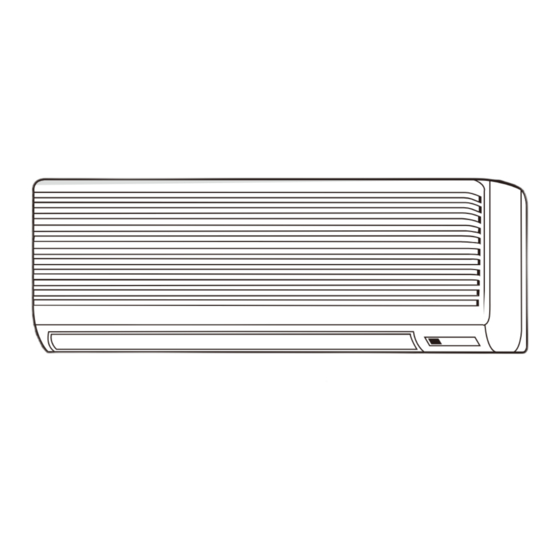
Indoor unit
[ Model names ]
PKH-2GKLA
Indoor unit
Remote controller
[ Service Ref. ]
PKH-2GKLA
ON/OFF
R22
CONTENTS
1. PART NAMES AND FUNCTIONS ....................... 2
2. SPECIFICATIONS ............................................... 4
3. DATA .................................................................... 7
4. OUTLINES AND DIMENSIONS ........................ 16
5. WIRING DIAGRAM ............................................ 17
6. REFRIGERANT SYSTEM DIAGRAM ..................... 18
7. OPERATION FLOW-CHART ............................. 19
8. MICROPROCESSOR CONTROL ..................... 23
9. TROUBLESHOOTING ....................................... 44
10. SYSTEM CONTROL .......................................... 55
11. DISASSEMBLY PROCEDURE .......................... 60
12. PARTS LIST ....................................................... 64
13. OPTIONAL PARTS ............................................ 66
October 2012
No. OC231
REVISED EDITION-A
Revision :
• The indicated No. of
CORNER COVER (page
65) has been corrected in
REVISED EDITION-A
.
• Some descriptions have been
modified.
• Please void OC231.
• This manual does not cover the
following outdoor units. When
servicing them, please refer to
the following service manual
and this manual in a set.
[Service Ref.]
PUH-2VKA
2
(OC128 REVISED EDITION-A)
PUH-2AKA
·TH-A
(OC156)
1
PUH-2NKA
(OC145)
1
Advertisement
Table of Contents

Related Manuals for Mitsubishi Electric PKH-2GKLA


Summary of Contents for Mitsubishi Electric PKH-2GKLA
-
Page 1: Table Of Contents
Indoor unit • The indicated No. of [ Model names ] [ Service Ref. ] CORNER COVER (page 65) has been corrected in PKH-2GKLA PKH-2GKLA REVISED EDITION-A • Some descriptions have been modified. • Please void OC231. • This manual does not cover the following outdoor units. -
Page 2: Part Names And Functions
Use the specified refrigerant only Never use any refrigerant other than that specified. Doing so may cause a burst, an explosion, or fire when the unit is being used, serviced, or disposed of. Correct refrigerant is specified in the manuals and on the spec labels provided with our products. We will not be held responsible for mechanical failure, system malfunction, unit breakdown or accidents caused by failure to follow the instructions. - Page 3 ● Wireless remote controller ● When cover is open. ADDRESS display display display Displays the refrigerant address. SET TEMP. display indicates desired tempera- Lights up while transmission to the indoor unit ture set. UNIT NO. display is mode using switches. Displays the number of unit.
-
Page 4: Specifications
SPECIFICATIONS Service Ref. PKH-2GKLA Item Function Cooling Heating 5,500 6,250 Capacity Btu/h 18,800 21,300 Total input 2.27 2.29 Service Ref. PKH-2GKLA Power supply(phase,cycle,voltage) Single, 50Hz, 220-240V Input 0.07 0.07 Running current 0.33 0.33 Starting current 0.40 0.40 External finish Munsell 0.70Y 8.59/0.97... - Page 5 Service Ref. PKH-2GKLA Item Function Cooling Heating 5,400 6,100 Capacity Btu/h 18,400 20,800 Total input 2.25 2.26 Service Ref. PKH-2GKLA Power supply(phase,cycle,voltage) Single, 50Hz, 240V Input 0.07 0.07 Running current 0.33 0.33 Starting current 0.40 0.40 External finish Munsell 0.70Y 8.59/0.97...
- Page 6 Service Ref. PKH-2GKLA Item Function CoolingT1/T2 HeatingT2 5,800/4,800 6,250 Capacity Btu/h 19,800/16,400 21,300 Total input 2.48/2.90 2.52 Service Ref. PKH-2GKLA Power supply(phase,cycle,voltage) Single, 60Hz, 220V Input 0.07 0.07 Running current 0.33 0.33 Starting current 0.40 0.40 External finish Munsell 0.70Y 8.59/0.97...
-
Page 7: Data
DATA 1. PERFORMANCE DATA 1) COOLING CAPACITY<1> 50Hz (Outdoor unit : PUH-2VKA PKH-2GKLA Outdoor intake air D.B.(°C) Indoor Indoor Intake air Intake air D.B.(°C) W.B.(°C) SHC(W) P.C. SHC(W) P.C. SHC(W) P.C. 5549 3274 0.59 1.82 5397 3184 0.59 1.90 5198 3067 0.59... - Page 8 COOLING CAPACITY<2> 50Hz (Outdoor unit : PUH-2VKA PKH-2GKLA Outdoor intake air D.B.(°C) Indoor Indoor Intake air Intake air D.B.(°C) W.B.(°C) SHC(W) P.C. SHC(W) P.C. SHC(W) P.C. 0.59 0.59 0.59 4988 2943 2.19 4765 2811 2.34 4530 2673 2.49 5323 2502 0.47...
- Page 9 COOLING CAPACITY<3> 50Hz (Outdoor unit : PUH-2AKA ·TH-A) PKH-2GKLA Outdoor intake air D.B.(°C) Indoor Indoor Intake air Intake air D.B.(°C) W.B.(°C) SHC(W) P.C. SHC(W) P.C. SHC(W) P.C. 5448 3269 0.60 1.80 5299 3179 0.60 1.88 5104 3062 0.60 2.02 5800 2784 0.48...
- Page 10 COOLING CAPACITY<4> 50Hz (Outdoor unit : PUH-2AKA ·TH-A) PKH-2GKLA Outdoor intake air D.B.(°C) Indoor Indoor Intake air Intake air D.B.(°C) W.B.(°C) SHC(W) P.C. SHC(W) P.C. SHC(W) P.C. 0.60 0.60 0.60 4897 2938 2.17 4678 2807 2.32 4447 2668 2.46 5226 2509 0.48...
- Page 11 COOLING CAPACITY<5> 60Hz (Outdoor unit : PUH-2NKA PKH-2GKLA Indoor Outdoor intake air D.B.(°C) intake W.B.(°C) P.C. P.C. P.C. P.C. P.C. P.C. 5,851 1.99 5,691 2.07 5,482 2.23 5,260 2.39 5,025 2.55 4,777 2.72 6,230 2.03 6,066 2.11 5,845 2.28 5,613 2.45...
- Page 12 2. PERFORMANCE CURVE Cooling Heating INDOOR W.B.(°C) INDOOR D.B. (°C) INDOOR W.B.(°C) INDOOR D.B. (°C) -12-10 OUTDOOR W.B. (°C) OUTDOOR D.B.(°C) OC231A...
-
Page 13: Electrical Data
3. ELECTRICAL DATA Indoor unit 220V 50Hz 1phase, 230V 50Hz 1phase, 230V 50Hz 1phase Outdoor unit 220V 50Hz 1phase, 230V 50Hz 1phase, 240V 50Hz 1phase Indoor unit PKH-2GKLA PKH-2GKLA PKH-2GKLA Service Ref. Outdoor unit PUH-2VKA PUH-2VKA PUH-2VKA Mode Heat Cool... -
Page 14: Oc231A
4. STANDARD OPERATION DATA Service Ref. PKH-2GKLA PKH-2GKLA PKH-2GKLA Mode Cooling Heating Cooling Heating Cooling Heating Capacity 5,500 6,250 5,400 6,100 5,800 6,250 Input 2.27 2.29 2.25 2.26 2.48 2.52 Indoor unit PKH-2GKLA PKH-2GKLA PKH-2GKLA Service Ref. Phase,Hz 1,50 1,50... - Page 15 6. NOISE CRITERION CURVES PKH-2GKLA SPL(dB) LINE NOTCH NC-70 NC-60 NC-50 NC-40 NC-30 APPROTIMATE THRESHOLD OF HEARING FOR NC-20 CONTINUOUS NOISE 1000 2000 4000 8000 BAND CENTER FREQUENCIES, Hz UNIT WALL Ambient temperature 27 Test conditions are based on JIS Z8731...
-
Page 16: Outlines And Dimensions
OUTLINES AND DIMENSIONS Unit : mm INDOOR UNIT PKH-2GKLA Front view Left side Right side Air intake Less than 15 Air intake Air intake Knockout hole for left piping Knockout hole for right piping ON STAND COOL HEAT MITSUBISHI ELECTRIC r.SLI... -
Page 17: Wiring Diagram
WIRING DIAGRAM PKH-2GKLA The black square ( ) indicates a switch position. OC231A... -
Page 18: Refrigerant System Diagram
REFRIGERANT SYSTEM DIAGRAM PKH-2GKLA / PUH-2VKA PUH-2AKA ·TH-A Unit : mm <4-Way valve solenoid coil> Heating ON Refrigerant flow in cooling Cooling OFF Refrigerant flow in heating High pressure control switch Oil separator Refrigerant pipe Outdoor unit Service Indoor unit... -
Page 19: Operation Flow-Chart
OPERATION FLOW-CHART MAIN OPERATION START Power circuit breaker Check SW ON twice Operation SW “OFF” timer Set time “ON” timer complete Set time complete Trouble Remote controller operation display STOP Trouble STOP Operating mode (COOL) COOL operation PROTECTION DEVICE PROTECTION DEVICE SELF HOLD RELEASE SELF HOLD Operating mode... - Page 20 COOLING OPERATION COOL operation Four-way valve/OFF Initial COOLING Vane initial setting Vane 50 deg downward angle 60 deg downward angle Fan speed Downward discharge 1 hour Vane horizontal Vane setting notch airflow Compressor thermostat Allowance cancel 3-minute time delay 6-minute Allowance time delay period...
-
Page 21: Heating Operation
HEATING OPERATION Heat operation PKH-GKLA initial Heating area Type HEATING 3-minute Defrost release Vane setting notch Vane initial setting Auxiliary heater Defrost 30 min. elapse Pipe defrosting temperature Outdoor unit trouble thermistor is 60°C or higher Four-way valve ON FAN speed Low notch Hot adjust in process... -
Page 22: Dry Operation
DRY OPERATION operation Four-way valve / OFF Initial dry operation Vane Vane initial setting setting notch Room temperature is 18°C or lower During compressor ON 3-minute 3-minute compressor time delay operation Compressor & Compressor & thermostat thermostat ON 10-minute Compressor ON compressor time completes Compressor ON... -
Page 23: Microprocessor Control
MICROPROCESSOR CONTROL 1. OUTLINE OF MICROPROCESSOR CONTROL Remote controller board INPUT to remote controller OUTPUT to remote controller ● Processes and transmits ● OFF-ON switching Remote controller orders ● COOL/DRY-AUTO-HEAT selector switching ● LCD indicator ● Thermostat setting ● TIMER mode selector-switching and Timer setting ●... -
Page 24: Indoor Unit Control
2. INDOOR UNIT CONTROL 2-1 COOL operation <How to operate> 1 Press POWER ON/OFF button. ADDRESS UNIT No. FUNCTION No. °C SELECTION No. 2 Press the MODE button to display “ ”. FUNCTION TEST RUN 3 Press the TEMP button to set the desired temperature. CHECK TEMP. - Page 25 (2) Indoor fan control Indoor fan speed LOW/HIGH depends on the remote controller setting. However, if an outdoor unit abnormality is detected, the indoor fan speed will be LOW, regardless of the remote controller setting. ( i ) Fan speed LOW/HIGH depends on the remote controller setting regardless of the thermostat ON/OFF. (ii) Fan speed will remain on LOW if an abnormality in outdoor unit is detected.
- Page 26 (3) Auto vane control Auto vane position is set to 10 degrees airflow at the start-up of COOL operation. It can then be changed by the remote controller. (a) Stop mode (fixed operation) ( i ) At start-up of COOL operation, the auto vane is set to 10 degrees airflow direction. ( ii ) Discharge direction can be changed with VANE button.
- Page 27 <Auto vane drive> (a) The vane is driven by DC12V motor. (b) Airflow direction is selected depends on the number of pulse were sent. (c) Before start driving the auto vane, detect the standard position first, output the number of pulse to each airflow. (d) The speed of the auto vane drive for both open and close are set at 200 pulse/sec.
- Page 28 2-2 DRY operation <How to operate> 1 Press POWER ON/OFF button. 2 Press the MODE button to display “ ”. ADDRESS UNIT No. FUNCTION No. °C SELECTION No. 3 Press the TEMP button to set the desired temperature. FUNCTION TEST RUN NOTE: The set temperature changes 1°C when the CHECK TEMP.
- Page 29 (1) Compressor control 13-minute time delay To prevent overload, the compressor will not start within 3 minutes after stop. 2The compressor runs when the room temperature is higher than the set temperature. The compressor stops when the room temperature is equal to or lower than the set temperature. 3The compressor stops in check mode or during protective functions.
- Page 30 <How to operate> 2-3 HEAT operation 1 Press POWER ON/OFF button. 2 Press the MODE button to display “ ”. ADDRESS UNIT No. 3 Press the TEMP button to set the desired temperature. FUNCTION No. °C SELECTION No. NOTE: The set temperature changes 1°C when the button is FUNCTION TEST RUN...
- Page 31 (2) Indoor fan control (a) Normal control (!)The indoor fan runs on EXTRA-LOW speed during the thermostat OFF. EXTRA-LOW speed can be changed to LOW or HIGH speed by setting the dipswitch SW1-5 and SW1-6, If the pipe temperature becomes more than 5 degrees below the room temperature during the thermostat OFF, the indoor fan will stop.
- Page 32 (4) Detecting abnormalities in the outdoor unit When the outdoor unit is determined to be abnormal by the following causes, the compressor will stop and the check code “ P8 ” will appear on the remote controller display. ( i ) During compressor ON while hot adjustment is set. 1 If the difference between the pipe temperature and room temperature is in the RANGE B , the indoor fan will stop.
- Page 33 2-4 AUTO operation (Automatic COOL/HEAT change over operation) <How to operate> 1 Press POWER ON/OFF button. ADDRESS UNIT No. 2 Press the MODE button to display “ ”. FUNCTION No. °C SELECTION No. 3 Press the TEMP button to set the desired temperature. FUNCTION TEST RUN CHECK...
- Page 34 2-5 Auto vane control <How to operate> To change the airflow direction, press VANE button. ADDRESS UNIT No. FUNCTION No. °C SELECTION No. FUNCTION TEST RUN CHECK TEMP. ON/OFF 10° 30° Available in COOL operation with fan speed on HIGH or in HEAT operation.
- Page 35 <How to operate> 2-6 TIMER operation 1 Press the ON/OFF button to turn it ON. 2 Press the STOP or START button (TIMER SET). · Time can be set while the following symbol is displayed. ▼ OFF timer : A is displayed.
- Page 36 (1) Pipe temperature code During the test run, the pipe temperature code from 1 to 15 is displayed on the remote controller instead of room tem- perature. The code should fall with the lapse of time in normal COOL operation, and should rise in normal HEAT opera- tion.
- Page 37 2-9 Interlock with ventilation system (LOSSNAY) Mr. SLIM/LOSSNAY interlock operation is available by using the optional parts listed below. (1) System organization Relay box (PZ-12RB-E) Relay box Mr. SLIM LOSSNAY Power supply LOSSNAY Mr. SLIM Power supply Remote display Remote adapter controller Remote...
- Page 38 2-10 Dip switch functions The black square ( ) indicates a switch position. Each figure shows the initial factory setting. 1. On remote controller board (Option: Wired remote controller) (1) SW17 (Address selector) 1 2 3 4 5 6 7 8 SW17-1~6) For address setting SW17-7) When two remote controllers are used, this switch sets the controller function.
- Page 39 Switch to set the output of phase-controlled indoor fan motor. Address setting is available at any time. The initial factory setting by is based on each capacity. Service Ref. PKH-2GKLA 1 2 3 (7) SW8 1 2 3 4 SW8-1~5) Not for use.
-
Page 40: Outdoor Unit Control
3. OUTDOOR UNIT CONTROL 3-1 Outdoor fan control The rotational frequency of outdoor fan is phase-controlled according to the outdoor coil temperature. This control allows the cooling operation even with the low outside-air temperature and the heating operation even with the high outside-air tempera- ture. - Page 41 3-5 Defrosting in HEAT mode <Defrosting time chart> Defrosting Defrosting starts. stops. Indoor unit Indoor fan Auto vane Set direction Set direction Outdoor unit 4-way valve Bypass valve Outdoor fan Compressor (1) Start conditions A. When all of the following conditions are satisfied, defrosting will start. However, when the bypass valve turns OFF, defrosting starts 10 minutes later.
- Page 42 (3) Defrost interval The defrost interval time is determined as follows. ● Initial defrost interval is 50 minutes. ● The defrost interval after defrosting depends on the preceding defrosting time as shown below. Defrosting operation time Next defrost interval 3 minutes or below 120 minutes 3 to 7 minutes 80 minutes...
- Page 43 3-7 Service functions (1) Compulsory defrosting 1 When all of the following conditions are satisfied, pressing SW2 starts the compulsory defrosting. ● During HEAT mode ● The compressor is ON. ● The outdoor coil temperature is being displayed by LED. (Outdoor controller board dip switch SW3-1 : OFF, SW3-2 : ●...
-
Page 44: Troubleshooting
TROUBLESHOOTING 1. TROUBLE IN TEST RUN Symptom Cause Check points The display “CENTRALLY 1) Wrong address setting of remote con- 1) Check the address setting of remote controller CONTROLLED” on remote troller/indoor controller board and indoor controller. controller dose not disap- 2) Timer adapter is connected to the 2) Make sure the timer adapter is used correctly. - Page 45 (WIRELESS REMOTE CONTROLLER) Remove the battery cover on the back side of (1) Turn on the main power of the unit. the wireless remote controller, display will start (2) Set the adjusting switch on the back of the flashing when the “Set” switch is turned on. wireless remote controller to “Set”...
- Page 46 (WIRED REMOTE CONTROLLER) : Optional part 2-1 When malfunction occurs during operation When a malfunction occurs, the indoor and outdoor units stop and the malfunction is displayed on the LCD of the remote controller. (1) ON the set temperature display part, “CHECK” appears, and the unit address and the check code are displayed alter- nately at one-second intervals.
- Page 47 Check Diagnosis of malfunction Cause Check points code Signal transmitting/receiving During individual unit control 1) Check the transmission wire. error 1) Bad contact of transmission wire 2) Check with another remote controller. If “EO” (Indoor controller does not 2) Signal transmitting/receiving cir- is still indicated, replace the indoor controller respond to remote controller cuit is abnormal.
- Page 48 3. SERVICE DATA INDICATION BY SWITCHES ON OUTDOOR CONTROLLER BOARD Setting dip switches SW2 and SW3 on the outdoor controller board enables LED to show the output state and check code. Output state is shown by LED lighting, and check code by blinking. SW1 : Turning SW1 ON clears the check code.
- Page 49 3-1 Outdoor coil temperature To obtain data on the outdoor coil temperature, add the number of bits of lighting LEDs, and see the graph below to find the temperature. Short Open 3-2 Fan output step To obtain data on the fan output step, add the number of bits of lighting LEDs, and see the graph below to find the fan rota- tional frequency.
- Page 50 4. TROUBLESHOOTING ACCORDING TO CHECK CODE Blinking Diagnosis of malfunction Cause Check point Reversed phase Phases L , and L are con- Check the power supply connection. nected improperly. ● Phase L ● Check the power supply. Open phase is open. ●...
- Page 51 6. WRONG WIRING ON SITE 6-1 Between remote controller and indoor unit If the wire is disconnected between the remote controller and the indoor unit, nothing is displayed on the remote controller when the POWER button is pressed. The beep sound will also not be heard. 6-2 Phenomenon due to wrong wiring between indoor and outdoor units Wrong wiring Mode...
- Page 52 7. OTHER TROUBLES AND CAUSES Vanes do not work. Vane motor is damaged. Vane motor does not work. Vane motor relay is damaged. Connector is poorly connected. Vane motor is poorly assembled. Indoor controller board is damaged. Refer to check code on remote controller display. Unit stops after 5 to 20 Protection function is working.
- Page 53 8. MR. SLIM/LOSSNAY INTERLOCK OPERATION <Symptoms that are not malfunctions> If any of the following symptoms occur, they are not malfunctions. Symptom Cause LOSSNAY control switch can not work during interlock opera- tion. LOSSNAY control switch does not work. LOSSNAY control switch is effective only while Mr. SLIM is not operating.
- Page 54 9. How to check the parts PKH-2GKLA Parts name Check points Room temperature Disconnect the connector, then measure the resistance with a tester. thermistor (RT1) (Surrounding temperature 10°C~30°C) Pipe temperature thermistor (RT2) Normal Abnormal (Refer to the thermistor) 4.3k ~9.6k...
-
Page 55: System Control
SYSTEM CONTROL 1. VARIETY OF SYSTEM CONTROL FUNCTIONS [Only optional wired remote controller is available the following system.] Many units, installed at different locations, can be started 1 Group control with and controlled with a single remote controller. The remote a single remote controller can be mounted in a different location using a controller... - Page 56 2. GROUP CONTROL WITH A SINGLE REMOTE CONTROLLER A maximum of 50 units can be started in order according to the dip switch settings. 2-1 How to wire Figure 1 (1) Connect the remote controller to the double terminal block on the indoor controller board of the master unit (No.0 unit).
- Page 57 3. CONTROL USING TWO REMOTE CONTROLLERS : OPTIONAL REMOTE CONTROLLER (PAR-JA240KAT-E) Two remote controllers can be used to control either one unit or a group of units. Units operate according to the latest com- mand from either of the two remote controllers. Before operation, be sure to set one remote controller as the “main controller”...
- Page 58 NOTE1 : Install the relay box where you can be serviced it easily. NOTE2 : For control circuit wiring, use a wire of No. 14 AWG or a control cable according to the power supply of control circuit. NOTE3 : When the power supply of the control circuit is 220/240V AC, ●...
-
Page 59: Auto Restart Function
6. MULTIPLE REMOTE CONTROL DISPLAY You can control several units with a multiple remote control display, by wir- Indoor controller board ing an optional multiple remote controller adapter (PAC-SA88HA-E) with relays and lamps on the market. 6-1 How to wire (1) Connect the multiple display adapter to the connector CN51 on the indoor controller board. -
Page 60: Disassembly Procedure
DISASSEMBLY PROCEDURE PKH-2GKLA OPERATION PROCEDURE PHOTOS & ILLUSTRATION (Figure 1) Hook 1. REMOVING THE LOWER SIDE OF THE INDOOR UNIT FROM THE INSTALLATION PLATE (1) Remove the left / right corner box of the indoor unit. (2) Hold and pull down the lower and both ends of the indoor unit, and remove the ▼... -
Page 61: Operation Procedure
OPERATION PROCEDURE PHOTOS & ILLUSTRATION 4. REMOVING THE POWER BOARD (Photo 4) (1) Remove the front panel. (See Photo 1) (2) Remove the electrical parts box (2 screws). (See Photo 2) Power board (3) Disconnect the whole connector in the control board. (4) After lifting the controller case with pressing it’s convex section, remove the controller case and the control board simultaneously. - Page 62 OPERATION PROCEDURE PHOTOS & ILLUSTRATION 9. REMOVING THE FAN MOTOR (Photo 9) (1) Remove the terminal block cover. Motor cover (2) Remove the front panel. (See Photo 1) (3) Remove the electrical box. (See Photo 8) (4) Remove the nozzle assembly. (See Photo 7) (5) Remove the fan motor leg fixing 3 screws.
- Page 63 OPERATION PROCEDURE PHOTOS & ILLUSTRATION (Photo 13) 12. REMOVING THE SIGNAL RECEIVING P.C. BOARD Front (1) Remove the terminal block cover. panel (2) Disconnect the connector <yellow> for the wireless remote Set screws controller. (3) Remove the front panel. (See Photo 1) (4) Remove the 2 screws and signal receiving P.C.
-
Page 64: Parts List
PARTS LIST (non-RoHS compliant) ELECTRICAL PARTS PKH-2GKLA Wiring Recom- Remarks Specifications Parts No. Parts Name Diagram mended PKH-2GKLA (Drawing No.) Symbol Q'ty PM4V30-K T7W A01 762 FAN MOTOR R01 07Y 114 LINE FLOW FAN R01 07Y 105 RUBBER MOUNT R01 07Y 106... - Page 65 PARTS LIST (non-RoHS compliant) STRUCTURAL PARTS PKH-2GKLA Wiring Recom- Remarks Parts Name Parts No. Specifications PKH-2GKLA Diagram mended (Drawing No.) Symbol Q'ty R01 89Y 651 FRONT PANEL R01 A16 500 AIR FILTER R01 07Y 096 SCREW CAP R01 10Y 658...
-
Page 66: Optional Parts
OPTIONAL PARTS 1. REFRIGERANT PIPES Service Ref. : PKH-2GKLA Part No PAC-05FFS-E PAC-07FFS-E PAC-10FFS-E PAC-15FFS-E Pipe length Pipe size O.D. Liquid: 9.52 Gas: 15.88 Connection method Indoor unit:Flared Outdoor unit:Flared Note 1. How to connect refrigerant pipes. Factory supplied optional refrigerant pipings contain refrigerant at the above atmospheric pressures. As long as the connection takes no more than 5 minutes, no air will enter, and there will be no need for air purging. - Page 67 2-3. How to connect program timer (1) Install the program timer next to the remote controller the same way as the remote controller is installed. (2) Connect the program timer and the remote controller with a 6-wire cable as shown in the figure below. NOTE: While the program timer is connected to the remote controller, the 2-wire cable To indoor unit...
- Page 68 DUAL D U A L C E N T R A L O P E R A T I O N CENTRAL MITSUBISHI ELECTRIC 10 9 8 7 6 5 4 3 2 1 1 1 7 5-2. Functions POWER ON/OFF switch Operation ON/OFF switch.
- Page 69 5-3 Connection method (1) Connections in the power supply cord 1. Connect the power supply cord to the power supply terminal-block and fix it in-place with a tie-wrap. Connect a single phase 200V AC (220, 230, 240V) to A N. As E is the GND terminal, be sure to ground the earth wire.
- Page 70 6. PROGRAM TIMER ADAPTER This adapter is needed when a program timer (PAC-SC32PTA) or a centralized remote controller (PAC-805RC) is used. Part No. PAC-825AD 6-1 Parts included 1 ADAPTER 2 3-core cable 3 3-core cable Length : 2m (6' 7") Length : 2m (6' 7") 4 4-core cable 5 5-core cable...
- Page 71 OC231A...
- Page 72 HEAD OFFICE : TOKYO BLDG., 2-7-3, MARUNOUCHI, CHIYODA-KU TOKYO 100-8310, JAPAN cCopyright 2000 MITSUBISHI ELECTRIC CORPORATION Distributed in Oct. 2012 NO.OC231 REVISED EDITION-A New publication, effective Oct. 2012 Specifications are subject to change without notice. Distributed in Aug. 2000 NO.OC231...
Need help?
Do you have a question about the PKH-2GKLA and is the answer not in the manual?
Questions and answers