Table of Contents
Advertisement
Quick Links
SPLIT-TYPE, HEAT PUMP AIR CONDITIONERS
SPLIT-TYPE, AIR CONDITIONERS
SERVICE MANUAL
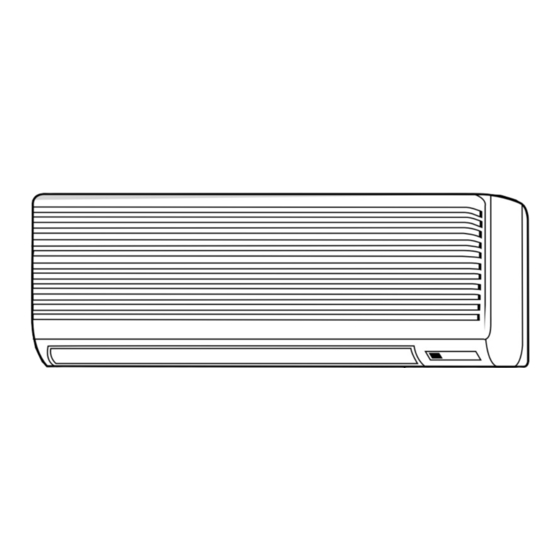
Indoor unit
[Model names]
PKA-RP35GAL
PKA-RP50GAL
PKH-P35GALH
PKH-P50GALH
Indoor unit
Remote controller
[Service Ref.]
PKA-RP35GAL
PKA-RP35GAL#1
PKA-RP50GAL
PKA-RP50GAL#1
PKH-P35GALH
PKH-P50GALH
Model name
indication
CONTENTS
1. TECHNICAL CHANGES ...................................... 2
2. REFERENCE MANUAL ....................................... 2
3. SAFETY PRECAUTION ....................................... 3
4. PART NAMES AND FUNCTIONS ........................ 7
5. SPECIFICATIONS ................................................ 9
6. NOISE CRITERION CURVES ............................ 11
7. OUTLINES AND DIMENSIONS ......................... 12
8. WIRING DIAGRAM ............................................. 13
9. REFRIGERANT SYSTEM DIAGRAM .................. 14
10. TROUBLESHOOTING ....................................... 15
11. SPECIAL FUNCTION ......................................... 30
12. DISASSEMBLY PROCEDURE ........................... 33
13. PARTS LIST ........................................................ 37
14. RoHS PARTS LIST ............................................. 40
February 2012
No.OC330
REVISED EDITION-C
Revision :
• The indicated No. of
CORNER COVER (page 37
and 42) have been corrected
in REVISED EDITION-C
.
• Some descriptions have
been modified.
• Please void OC330
REVISED EDITION-B.
Note :
• This manual describes only
service data of the indoor
units.
• RoHS compliant products
have <G> mark on spec
name plate.
For servicing of RoHS
compliant products, refer to
the RoHS Parts List.
Advertisement
Table of Contents

Subscribe to Our Youtube Channel
Related Manuals for Mitsubishi Electric Mr.Slim PKH Series


Summary of Contents for Mitsubishi Electric Mr.Slim PKH Series
-
Page 1: Table Of Contents
SPLIT-TYPE, HEAT PUMP AIR CONDITIONERS SPLIT-TYPE, AIR CONDITIONERS February 2012 No.OC330 REVISED EDITION-C SERVICE MANUAL Indoor unit Revision : [Service Ref.] [Model names] • The indicated No. of CORNER COVER (page 37 PKA-RP35GAL PKA-RP35GAL and 42) have been corrected in REVISED EDITION-C PKA-RP35GAL#1 •... -
Page 2: Technical Changes
TECHNICAL CHANGES PKA-RP35GAL PKA-RP35GAL#1 PKA-RP50GAL PKA-RP50GAL#1 INDOOR CONTROLLER BOARD(I.B.) has been changed. REFERENCE MANUAL 2-1. OUTDOOR UNIT’S SERVICE MANUAL Service Ref. Service Manual No. PUHZ-RP35/50/60/71/100/125/140VHA OC334 PUHZ-RP100/125/140YHA PUHZ-RP71/100/125/140VHA OC337 PUHZ-RP200/250YHA OC338 (1)(2) PUHZ-RP200/250YHA OC339 PU(H)-P • VGAA.UK OC336 PU(H)-P • YGAA.UK PUHZ-P100/125/140VHA.UK OC359 PUHZ-RP35/50/60/71/100/125/140VHA2... -
Page 3: Safety Precaution
SAFETY PRECAUTION 3-1. ALWAYS OBSERVE FOR SAFETY Before obtaining access to terminal, all supply circuits must be disconnected. 3-2. CAUTIONS RELATED TO NEW REFRIGERANT Cautions for units utilizing refrigerant R407C Do not use the existing refrigerant piping. Do not use a refrigerant other than R407C. If another refrigerant (R22, etc.) is used, the chlorine in the The old refrigerant and lubricant in the existing piping contains a large amount of chlorine which may cause the... - Page 4 [1] Cautions for service · After recovering the all refrigerant in the unit, proceed to working. · Do not release refrigerant in the air. · After completing the repair service, recharge the cycle with the specified amount of liquid refrigerant. [2] Refrigerant recharging (1) Refrigerant recharging process 1 Direct charging from the cylinder.
- Page 5 CAUTIONS RELATED TO NEW REFRIGERANT Cautions for units utilizing refrigerant R410A Use a vacuum pump with a reverse flow check Use new refrigerant pipes. valve. In case of using the existing pipes for R22, be careful with Vacuum pump oil may flow back into refrigerant cycle and the followings.
- Page 6 [1] Cautions for service (1) Perform service after collecting the refrigerant left in unit completely. (2) Do not release refrigerant in the air. (3) After completing service, charge the cycle with specified amount of refrigerant. (4) When performing service, install a filter drier simultaneously. Be sure to use a filter drier for new refrigerant.
-
Page 7: Part Names And Functions
PART NAMES AND FUNCTIONS Indoor unit Filter Air intake grille Air intake Auto vane Guide vane Air outlet OC330C... - Page 8 Wireless remote controller When the cover is open. CHECK TEST RUN display CHECK&TEST RUN display indicates that the unit is being checked or test-run. display MODEL SELECT Blinks when model is selected. display Lights up while transmission to the indoor unit is mode using switches.
-
Page 9: Specifications
SPECIFICATIONS Service Ref. PKA-RP35GAL, PKA-RP35GAL#1 Mode Cooling Heating Power supply(phase, cycle, voltage) Single phase, 50Hz, 230V Input 0.07 0.07 Running current 0.33 0.33 Starting current 0.40 0.40 External finish Munsell 0.70Y 8.59/0.97 Heat exchanger Plate fin coil Fan(drive) x No. Line flow (direct) x 1 Fan motor output 0.030... - Page 10 Service Ref. PKH-P35GALH Mode Cooling Heating Power supply(phase, cycle,voltage) Single phase, 50Hz, 230V Input 0.07 0.07<0.73> 0.33 0.33<3.17> Running current Starting current 0.40 0.40<3.17> External finish Munsell 0.70Y8.59/0.97 Heat exchanger Plate fin coil Line flow (direct) x 1 Fan(drive) x No. Fan motor output 0.030 9-10-11-12(318-353-388-424)
-
Page 11: Noise Criterion Curves
NOISE CRITERION CURVES NOTCH SPL(dB) LINE PKA-RP35/50GAL High Medium1 PKA-RP35/50GAL#1 Medium2 PKH-P35/50GALH NC-70 NC-60 NC-50 NC-40 NC-30 APPROXIMATE THRESHOLD OF HEARING FOR NC-20 CONTINUOUS NOISE 1000 2000 4000 8000 BAND CENTER FREQUENCIES, Hz UNIT WALL MICROPHONE OC330C 11 11... -
Page 12: Outlines And Dimensions
OUTLINES AND DIMENSIONS Unit : mm INDOOR UNIT PKH-P35GALH PKA-RP35GAL PKA-RP35GAL#1 PKH-P50GALH PKA-RP50GAL PKA-RP50GAL#1 OC330C... -
Page 13: Wiring Diagram
WIRING DIAGRAM PKH-P35GALH PKA-RP35GAL PKA-RP35GAL#1 PKH-P50GALH PKA-RP50GAL PKA-RP50GAL#1 CNDK CN2S (RED) (WHT) 1 (Fig.1) POWER DC13.1V SUPPLY ~(1PHASE) 230V 50Hz GRN/YLW OUTDOOR UNIT POWER POWER OUTDOOR VANE 1 3 5 CNDK UNIT CN6V ( WHT ) INDOOR/OUTDOOR (RED) (ORN) POWER ( GRN ) COMMUNICATION CN2D(WHT) -
Page 14: Refrigerant System Diagram
REFRIGERANT SYSTEM DIAGRAM PKH-P35GALH PKA-RP35GAL PKA-RP35GAL#1 PKH-P50GALH PKA-RP50GAL PKA-RP50GAL#1 Strainer Heat exchanger Refrigerant GAS pipe connection (Flare) Condenser/evaporator temperature thermistor (TH5) Refrigerant flow in cooling Refrigerant flow in heating Refrigerant LIQUID pipe connection (Flare) Pipe temperature thermistor/liquid Room temperature (TH2) thermistor (TH1) Strainer Distributor... -
Page 15: Troubleshooting
TROUBLESHOOTING 10-1. TROUBLESHOOTING <Error code display by self-diagnosis and actions to be taken for service (summary)> Present and past error codes are logged and displayed on the wired remote controller or controller board of outdoor unit. Actions to be taken for service and the trouble reoccurrence at field are summarized in the table below. Check the contents below before investigating details. - Page 16 10-2. MALFUNCTION-DIAGNOSIS METHOD BY REMOTE CONTROLLER <In case of trouble during operation> When a malfunction occurs to air conditioner, both indoor unit and outdoor unit will stop and operation lamp blinks to inform unusual stop. < Malfunction-diagnosis method at maintenance service> [Procedure] 1.
- Page 17 • Refer to the following tables for details on the check codes. [Output pattern A] Beeper sounds Beep Beep Beep Beep Beep Beep Beep OPERATION · · · Repeated INDICATOR lamp flash pattern Approx. 2.5 sec. 0.5 sec. 0.5 sec. 0.5 sec.
- Page 18 • On wireless remote controller The continuous buzzer sounds from receiving section of indoor unit. Blink of operation lamp • On wired remote controller Check code displayed in the LCD. • If the unit cannot be operated properly after test run, refer to the following table to find the cause. Symptom Cause Wired remote controller...
- Page 19 Note: Refer to the manual of outdoor unit for the details of display 10-3. SELF-DIAGNOSIS ACTION TABLE such as F, U, and other E. Abnormal point and detection method Countermeasure Error Code Cause 1 Defective thermistor 1–3 Check resistance value of thermistor. Room temperature thermistor (TH1) 0: ..
- Page 20 Abnormal point and detection method Countermeasure Error Code Cause Freezing/overheating protection is (Cooling or drying mode) (Cooling or drying mode) operating 1 Clogged filter (reduced airflow) 1 Check clogs of the filter. 1 Freezing protection (Cooling mode) 2 Short cycle of air path 2 Remove shields.
- Page 21 Abnormal point and detection method Countermeasure Error Code Cause 1 Defective thermistor 1–3 Check resistance value of thermistor. Pipe temperature thermistor/ For characteristics, refer to (P1) above. Condenser-Evaporator (TH5) characteristics 2 Check contact failure of connector (CN29) 1 The unit is in 3-minute resume protection 2 Contact failure of connector on the indoor controller board.
- Page 22 Abnormal point and detection method Countermeasure Error Code Cause 1 Contact failure, short circuit or, Indoor/outdoor unit communication * Check LED display on the outdoor control error (Signal receiving error) circuit board. (Connect A-control service miswiring (converse wiring) of 1 Abnormal if indoor controller board tool, PAC-SK52ST.) indoor/outdoor unit connecting cannot receive any signal normally for 6...
- Page 23 10-4. TROUBLESHOOTING OF PROBLEMS Note: Refer to the manual of outdoor unit for the detail of remote controller. Phenomena Cause Countermeasure (1) LED2 on indoor controller board • When LED1 on indoor controller board is also off. 1 Power supply of rated voltage is not supplied to 1 Check the voltage of outdoor power is off.
- Page 24 Note: Refer to the manual of outdoor unit for the detail of remote controller. Phenomena Cause Countermeasure (2) LED2 on indoor controller board • When LED1 on indoor controller board is also blinking. Check indoor/outdoor unit connecting wire Connection failure of indoor/outdoor unit connecting for connection failure.
- Page 25 10-5. EMERGENCY OPERATION 10-5-1. When wireless remote controller troubles or its battery is exhausted 1. Emergency operation is available in such a case using emergency operation switch equipped next to the receiver of indoor unit. 2. To start operation • Cooling Operation·······Press (Cooling) switch.
- Page 26 10-6. HOW TO CHECK THE PARTS PKH-P35GALH PKA-RP35GAL PKA-RP35GAL#1 PKH-P50GALH PKA-RP50GAL PKA-RP50GAL#1 Parts name Check points Room temperature Disconnect the connector then measure the resistance with a tester. thermistor (TH1) (Surrounding temperature 10 ~30 ) Pipe temperature thermistor (TH2) Normal Abnormal Condenser/evaporator (Refer to <Thermistor Characteristic graph>...
- Page 27 10-7. TEST POINT DIAGRAM 10-7-1. Indoor controller board PKA-RP35GAL PKA-RP35GAL#1 PKH-P35GALH PKA-RP50GAL PKA-RP50GAL#1 PKH-P50GALH CN2D LED1 LED2 LED3 Connect to the indoor Power supply (I.B) Power supply (R.B) Transmission (Indoor/ CN3C power board (CN2S) outdoor) Transmission (Indoor/ (12.5~13.7V DC) outdoor) CN22 (0~24V DC) Connect to the terminal...
- Page 28 10-7-2. Indoor power board PKA-RP35GAL PKA-RP35GAL#1 PKH-P35GALH PKA-RP50GAL PKA-RP50GAL#1 PKH-P50GALH CN2S Connect to the indoor controller board (CN2D) Between 1 to 3 12.6-13.7V DC (Pin1 (+)) CNSK Connect to the indoor controller board (CNDK) Between 1 to 3 220-240V AC OC330C...
- Page 29 10-8. FUNCTIONS OF DIP SWITCH AND JUMPER WIRE Each function is controlled by the dip switch and the jumper wire on control P.C. board. SW1 and SW2 are equipped only for service parts. Model setting and capacity setting are memorized in the nonvolatile memory of the control P.C. board of the unit.
-
Page 30: Special Function
SPECIAL FUNCTION 11-1. ROTATION FUNCTION (AND BACK-UP FUNCTION, 2ND STAGE CUT-IN FUNCTION) For PKA-RP35GAL#1, PKA-RP50GAL#1 11-1-1. Operation (1) Rotation function (and Back-up function) • Outline of functions · Main and sub unit operate alternately according to the interval of rotation setting. w Main and sub unit should be set by refrigerant address. - Page 31 11-1-2. How to set rotation function (Back-up function, 2nd stage cut-in function) You can set these functions by wired remote controller.( Maintenance monitor) NOTICE Both main and sub unit should be set in same setting. Every time replacing indoor controller board for servicing, the function should be set again. (1) Request Code List Rotation setting Setting No.
- Page 32 (2) Setting method of each function by wired remote controller B: Refrigerant address C: Data display area D: Request code display area 1. Stop operation( ). 2. Press the button ( ) for 3 seconds so that [Maintenance mode] appears on the screen ( ). TEST After a while, [00] appears in the refrigerant address number display area.(at 3.
-
Page 33: Disassembly Procedure
DISASSEMBLY PROCEDURE PKA-RP35GAL PKA-RP35GAL#1 PKH-P35GALH PKA-RP50GAL PKA-RP50GAL#1 PKH-P50GALH OPERATION PROCEDURE PHOTOS & ILLUSTRATION (Figure 1) Hook 1. REMOVING THE LOWER SIDE OF THE INDOOR UNIT FROM THE INSTALLATION PLATE (1) Remove the left / right corner box of the indoor unit. (2) Hold and pull down the lower and both ends of the indoor unit, and remove the ▼... - Page 34 OPERATION PROCEDURE PHOTOS & ILLUSTRATION 4. REMOVING THE POWER BOARD (Photo 4) (1) Remove the front panel. (See Photo 1) (2) Remove the electrical parts box (2 screws). (See Photo 2) Power board (3) Disconnect the whole connector in the control board. (4) After lifting the controller case with pressing it’s convex sec- tion, remove the controller case and the control board simul- taneously.
- Page 35 OPERATION PROCEDURE PHOTOS & ILLUSTRATION 9. REMOVING THE FAN MOTOR (Photo 9) (1) Remove the terminal block cover. (2) Disconnect the connector <yellow> of the wireless remote Motor cover controller board. (3) Remove the front panel. (See Photo 1) (4) Remove the electrical parts box. (See Photo 8) (5) Remove the nozzle assembly.
- Page 36 OPERATION PROCEDURE PHOTOS & ILLUSTRATION (Photo 14) 13. REMOVING the SIGNAL RECEIVING P.C. BOARD Front (1) Remove the terminal block cover. panel (2) Disconnect the connector <yellow> for the wireless remote Set screws controller. (3) Remove the front panel. (See Photo 1) (4) Remove the 2 screws and signal receiving P.C.
-
Page 37: Parts List
PARTS LIST (non-RoHS compliant) STRUCTURAL PARTS PKH-P35GALH, PKA-RP35GAL PKH-P50GALH, PKA-RP50GAL Wiring PKH- PKA- Recom- Remarks Parts No. Parts Name Specifications Diagram mended P35 / P50 RP35 / RP50 (Drawing No.) Symbol Q'ty GALH R01 07Y 808 BACK PLATE R01 10Y 658 CORNER COVER R01 07Y 623 UNDER COVER... - Page 38 (non-RoHS compliant) ELECTRICAL PARTS PKH-P35GALH, PKA-RP35GAL PKH-P50GALH, PKA-RP50GAL Wiring Recom- PKH- PKA- Remarks Specifications Parts No. Parts Name Diagram mended P35 / P50 RP35 / RP50 (Drawing No.) Symbol Q'ty GALH R01 E48 480 HEAT EXCHANGER HEAT EXCHANGER T7W E56 480 R01 09Y 114 LINE FLOW FAN LINE FLOW FAN...
- Page 39 (non-RoHS compliant) From the preceding page. Part number that is circled is not shown in the figure. PKH- Wiring Recom- PKA- Remarks Specifications Parts No. Parts Name Diagram mended P35 / P50 RP35 / RP50 (Drawing No.) Symbol Q'ty GALH —...
-
Page 40: Rohs Parts List
RoHS PARTS LIST ELECTRICAL PARTS PKH-P35GALH, PKA-RP35GAL, PKA-RP35GAL#1 PKH-P50GALH, PKA-RP50GAL, PKA-RP50GAL#1 Wiring Recom- PKA- PKH- Remarks Specifications Parts No. Parts Name Diagram mended P35 / P50 RP35 / RP50 (Drawing No.) Symbol Q'ty GALH GAL(#1) R01 E70 480 HEAT EXCHANGER T7W H36 480 HEAT EXCHANGER R01 E21 114... - Page 41 (RoHS PARTS LIST) From the preceding page. Part number that is circled is not shown in the figure. PKH- PKA- Wiring Recom- Remarks Parts No. Parts Name Specifi cations Diagram mended P35/P50 RP35/RP50 RP35/RP50 (Drawing No.) Symbol Q'ty GALH GAL#1 18 G —...
- Page 42 (RoHS PARTS LIST) STRUCTURAL PARTS PKH-P35GALH, PKA-RP35GAL, PKA-RP35GAL#1 PKH-P50GALH, PKA-RP50GAL, PKA-RP50GAL#1 PKH- PKA- Wiring Recom- Remarks Parts No. Parts Name Specifi cations Diagram mended P35/P50 RP35/RP50 RP35/RP50 (Drawing No.) Symbol Q'ty GALH GAL#1 R01 08Y 808 BACK PLATE R01 10Y 658 CORNER COVER(R) R01 08Y 623 UNDER COVER R01 E05 651 FRONT PANEL R01 08Y 096 SCREW CAP...
- Page 43 OC330C...
- Page 44 HEAD OFFICE : TOKYO BLDG., 2-7-3, MARUNOUCHI, CHIYODA-KU, TOKYO 100-8310, JAPAN CCopyright 2005 MITSUBISHI ELECTRIC CORPORATION Distributed in Feb. 2012 No.OC330 REVISED EDITION-C Distributed in May 2008 No.OC330 REVISED EDITION-B PDF 7 New publication, effective Feb. 2012 Distributed in Jun. 2006 No.OC330 REVISED EDITION-A PDF 8 Specifications are subject to change without notice.
Need help?
Do you have a question about the Mr.Slim PKH Series and is the answer not in the manual?
Questions and answers