
Related Manuals for REXROTH IndraControl L25 Series


Summary of Contents for REXROTH IndraControl L25 Series
- Page 1 Electric Drives Linear Motion and and Controls Hydraulics Assembly Technologies Pneumatics Service Rexroth IndraControl R911328474 Edition 03 Project Planning Manual...
- Page 2 04.2011 Third edition Copyright © Bosch Rexroth AG 2009 Copying this document, giving it to others and the use or communication of the contents thereof without express authority, are forbidden. Offenders are liable for the payment of damages. All rights are reserved in the event of the grant of a patent or the registration of a utility model or design (DIN 34-1).
-
Page 3: Table Of Contents
DOK-CONTRL-IC*L25*****-PR03-EN-P Bosch Rexroth AG I/69 Rexroth IndraControl L25 Table of Contents Table of Contents Page System Presentation...................... 5 Brief Description IndraControl L25......................5 Device Variants............................5 View................................ 5 Further Documentation........................... 6 Important Instructions on Use..................7 Intended Use............................7 2.1.1 Introduction............................ - Page 4 Mechanical Installation of IndraControl L25..................43 8.1.1 General Information........................... 43 8.1.2 Mounting the IndraControl L25......................43 8.1.3 Dismounting the IndraControl L25..................... 44 Mechanical Installation of Rexroth Inline Terminals................45 8.2.1 General Information........................... 45 8.2.2 Mounting the Inline Terminals......................45 8.2.3 Demounting the Inline Terminals....................... 46 8.2.4...
- Page 5 Accessories............................60 10.2.1 Spare Part (Power Connector)......................60 General Information........................60 10.2.2 Further Accessories (Rexroth Inline Terminals, Function Modules and Interface Cables)....60 Rexroth Inline Terminals......................... 60 Rexroth Function Modules......................60 Interface Cables..........................61 Service and Support....................65 Index..........................67...
- Page 6 IV/69 Bosch Rexroth AG DOK-CONTRL-IC*L25*****-PR03-EN-P Rexroth IndraControl L25...
-
Page 7: System Presentation
Up to two function modules extend the IndraControl L25 via integra‐ ted PCI bus and additional fieldbus interfaces and technology interfaces. The locally available I/O units can be extended by the Rexroth Inline I/O system, just by simply mounting the components side by side. The complete application programs, including runtime, are stored on an easily accessible Compact Flash card. -
Page 8: Further Documentation
6/69 Bosch Rexroth AG DOK-CONTRL-IC*L25*****-PR03-EN-P Rexroth IndraControl L25 System Presentation Further Documentation Title Identification Parts number PLC Programming with Rexroth DOK-CONTRL-IL**PRO*V01- R911305036 IndraLogic 1.0; AW02-EN-P Operating and Programming Guide RECO-Inline PROFIBUS DP; DOK-CONTRL-R-IL-PBSSYS- R911289597 AW02-EN-P Application Manual RECO Inline PROFIBUS DP Ter‐... -
Page 9: Important Instructions On Use
Before using Bosch Rexroth products, the following requirements must be met to ensure intended use of the products: ● Anyone handling one of the Rexroth products in any way has to read and understand the respective safety-related guidelines as well as the instruc‐ tions on intended use. -
Page 10: Inappropriate Use
8/69 Bosch Rexroth AG DOK-CONTRL-IC*L25*****-PR03-EN-P Rexroth IndraControl L25 Important Instructions on Use The IndraControl L25 may only be operated under the assembly and installation conditions, in the position of application and under the ambient conditions (tem‐ perature, degree of protection, humidity, EMC, etc.) specified in this documen‐... -
Page 11: Safety Instructions For Electric Drives And Controls
DOK-CONTRL-IC*L25*****-PR03-EN-P Bosch Rexroth AG 9/69 Rexroth IndraControl L25 Safety Instructions for Electric Drives and Controls Safety Instructions for Electric Drives and Controls Definitions of Terms Application Documentation Application documentation comprises the entire documentation used to inform the user of the product about the use and safety-relevant features for config‐... -
Page 12: General Information
You must follow these safety instructions. ● Bosch Rexroth is not liable for damages resulting from failure to observe the safety instructions. ●... -
Page 13: Hazards By Improper Use
DOK-CONTRL-IC*L25*****-PR03-EN-P Bosch Rexroth AG 11/69 Rexroth IndraControl L25 Safety Instructions for Electric Drives and Controls concept in which measures of risk reduction for personal safety depend on electrical, electronic or programmable control systems. ● The information given in the application documentation with regard to the use of the delivered components contains only examples of applications and suggestions. - Page 14 12/69 Bosch Rexroth AG DOK-CONTRL-IC*L25*****-PR03-EN-P Rexroth IndraControl L25 Safety Instructions for Electric Drives and Controls ● Risk of injury by improper handling! Injury by crushing, shearing, cutting, hitting! ● Risk of injury by improper handling of batteries! ● Risk of injury by improper handling of pressurized lines!
-
Page 15: Instructions With Regard To Specific Dangers
DOK-CONTRL-IC*L25*****-PR03-EN-P Bosch Rexroth AG 13/69 Rexroth IndraControl L25 Safety Instructions for Electric Drives and Controls Instructions with Regard to Specific Dangers 3.3.1 Protection Against Contact With Electrical Parts and Housings This section concerns components of the electric drive and control system with voltages of more than 50 volts. -
Page 16: Protective Extra-Low Voltage As Protection Against Electric Shock
On components of an electric drive and control system provided by Bosch Rexroth, all connections and terminals with voltages between 5 and 50 volts are PELV ("Protective Extra-Low Voltage") systems. It is allowed to connect devices equipped with basic insulation (such as programming devices, PCs, notebooks, display units) to these connections. - Page 17 DOK-CONTRL-IC*L25*****-PR03-EN-P Bosch Rexroth AG 15/69 Rexroth IndraControl L25 Safety Instructions for Electric Drives and Controls ● Improper or wrong wiring or cable connection ● Operator errors ● Wrong input of parameters before commissioning ● Malfunction of sensors and encoders ●...
-
Page 18: Protection Against Magnetic And Electromagnetic Fields During Operation And Mounting
16/69 Bosch Rexroth AG DOK-CONTRL-IC*L25*****-PR03-EN-P Rexroth IndraControl L25 Safety Instructions for Electric Drives and Controls ● The standard equipment motor holding brake or an external holding brake controlled by the drive controller is not sufficient to guarantee personal safety! ●... -
Page 19: Protection During Handling And Mounting
DOK-CONTRL-IC*L25*****-PR03-EN-P Bosch Rexroth AG 17/69 Rexroth IndraControl L25 Safety Instructions for Electric Drives and Controls ● After switching chokes, supply units and drive controllers off, wait 15 mi‐ nutes to allow them to cool down before touching them. ● Wear safety gloves or do not work at hot surfaces. -
Page 20: Protection Against Pressurized Systems
18/69 Bosch Rexroth AG DOK-CONTRL-IC*L25*****-PR03-EN-P Rexroth IndraControl L25 Safety Instructions for Electric Drives and Controls 3.3.8 Protection Against Pressurized Systems According to the information given in the Project Planning Manuals, motors and components cooled with liquids and compressed air can be partially supplied with externally fed, pressurized media, such as compressed air, hydraulics oil, cooling liquids and cooling lubricants. - Page 21 DOK-CONTRL-IC*L25*****-PR03-EN-P Bosch Rexroth AG 19/69 Rexroth IndraControl L25 Safety Instructions for Electric Drives and Controls NOTICE In case of non-compliance with this safety instruction, property damage could occur.
- Page 22 20/69 Bosch Rexroth AG DOK-CONTRL-IC*L25*****-PR03-EN-P Rexroth IndraControl L25...
-
Page 23: Technical Data
DOK-CONTRL-IC*L25*****-PR03-EN-P Bosch Rexroth AG 21/69 Rexroth IndraControl L25 Technical Data Technical Data Equipment Processor Renesas SH 7785 Min. 128 MByte DRAM and min. 256 kByte RDS Clock frequency 576 MHz (CPU CLK) Interfaces: Interface to function ● Bosch Rexroth PC104... -
Page 24: Ambient Conditions
22/69 Bosch Rexroth AG DOK-CONTRL-IC*L25*****-PR03-EN-P Rexroth IndraControl L25 Technical Data Ambient Conditions In operation Storage / Transport Max. surrounding air +5 ... +55 °C -25 ℃ to +70 ℃ temperature Relative humidity RH-2; 5 % to 95 % acc. to DIN EN 61131-2, RH-2;... -
Page 25: Ul And Csa Certified
UL and CSA compliance must be verified. Compatibility Test All Rexroth controls and drives are developed and tested according to the latest state-of-the-art of technology. As it is not possible to follow the continuing development of all materials (e. g. -
Page 26: Wear Parts
24/69 Bosch Rexroth AG DOK-CONTRL-IC*L25*****-PR03-EN-P Rexroth IndraControl L25 Technical Data For this reason, before using the respective material a compatibility test has to be carried out for new materials (e. g. lubricants and cleaning agents) and our housing or our housing materials. -
Page 27: Dimensions
DOK-CONTRL-IC*L25*****-PR03-EN-P Bosch Rexroth AG 25/69 Rexroth IndraControl L25 Dimensions Dimensions General Information All values in the illustrations are given in mm. Housing Dimensions The width of the IndraControl L25 is 175.4 mm, the height is 120 mm and the depth is 84.7 mm. Please refer to the following figures for detailed dimensions: Fig.5-1:... -
Page 28: Installation Notes
26/69 Bosch Rexroth AG DOK-CONTRL-IC*L25*****-PR03-EN-P Rexroth IndraControl L25 Dimensions Fig.5-3: Left view (the cut-out for the top-hat rail is located in the center) Installation Notes ● Avoid installation locations that are exposed to direct sunlight because this causes additional heat. -
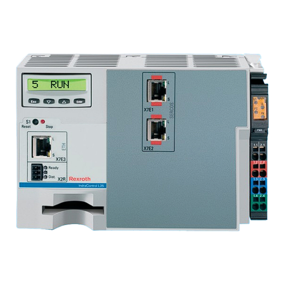
Page 29: Display And Operating Components
DOK-CONTRL-IC*L25*****-PR03-EN-P Bosch Rexroth AG 27/69 Rexroth IndraControl L25 Display and Operating Components Display and Operating Components General Information On its front, the IndraControl L25 is provided with the following display and operating components: a single-line display with four operating keys as well as a LED and a Reset button. - Page 30 28/69 Bosch Rexroth AG DOK-CONTRL-IC*L25*****-PR03-EN-P Rexroth IndraControl L25...
-
Page 31: Connections And Interfaces
DOK-CONTRL-IC*L25*****-PR03-EN-P Bosch Rexroth AG 29/69 Rexroth IndraControl L25 Connections and Interfaces Connections and Interfaces Connections on the Front Panel – Overview Designa‐ Connection type Connector type Mating connec‐ Notes on de‐ tion at the tor and cable vice variants (integrated) - Page 32 30/69 Bosch Rexroth AG DOK-CONTRL-IC*L25*****-PR03-EN-P Rexroth IndraControl L25 Connections and Interfaces View IndraControl L25, CML...3N... device variant X7E1 X7E2 X7E5 ① Slot for Compact Flash card ② PWR IN voltage supply Fig.7-1: IndraControl L25 connections, CML...3N... device variant CAUTION Fitting or removing connectors when voltage is...
-
Page 33: Voltage Supply
DOK-CONTRL-IC*L25*****-PR03-EN-P Bosch Rexroth AG 31/69 Rexroth IndraControl L25 Connections and Interfaces View IndraControl L25, CML...PN... device variant X7E3 X7E4 X7E5 ① Slot for Compact Flash card ② PWR IN voltage supply Fig.7-2: IndraControl L25 connections, CML...PN... device variant CAUTION Fitting or removing connectors when voltage is... - Page 34 32/69 Bosch Rexroth AG DOK-CONTRL-IC*L25*****-PR03-EN-P Rexroth IndraControl L25 Connections and Interfaces Fig.7-3: Connector for supply voltages Observe the color-coding of the connectors. For connecting the operating voltages only the power connector (R- IB IL SCN-PWR IN-PWR) may be used. The connector is contained in the scope of delivery.
-
Page 35: Voltage Supply Uls
DOK-CONTRL-IC*L25*****-PR03-EN-P Bosch Rexroth AG 33/69 Rexroth IndraControl L25 Connections and Interfaces Connector con‐ Signal tact DC +24 V segment voltage (U DC +24 V supply voltage (U LGND (ground, supply voltage) 1.4 and 2.4 FE (functional earth ground) DC 24 V main voltage (U... -
Page 36: 24 V Voltage Supply Of The Main Circuit U
Segment circuit supply U has to be connected to contact 1.1 and is lead through the following series Rexroth Inline I/O terminals. It forms the segment circuit or auxiliary circuit (via voltage jumpers) of the Rexroth Inline terminals and the onboard I/Os. - Page 37 DOK-CONTRL-IC*L25*****-PR03-EN-P Bosch Rexroth AG 35/69 Rexroth IndraControl L25 Connections and Interfaces The segment circuit with the segment voltage U starts at the IndraCon‐ trol L25 or a supply terminal (power terminal or segment terminal) and is supplied through all following terminals up to the next supply terminal.
-
Page 38: Internally Generated Voltages
IndraControl L25 and is supplied through all connected Rexroth Inline I/O terminals. It is the logic voltage supply (via voltage jumpers) of the Rexroth Inline terminals. This logic circuit starts at the IndraControl L25 and is supplied through all ter‐... -
Page 39: Ethernet Interface (Only For Device Variant Cml
Ethernet RJ45 To the Network Zum Netzwerk Fig.7-12: Ethernet interface Bosch Rexroth recommends to use a STP cable of category 5. This port is intended for the programming device network! Status L (link) On: Link to network is available Off: No connection to network is available... -
Page 40: Profibus Dp (Only For Device Variant Cml
Zum Netzwerk Fig.7-13: Ethernet interface Bosch Rexroth recommends to use a STP cable of category 5. According to the configuration in the application software, these connections can be used for another TCP/IP network or for an RT Ethernet network. The two plugs correspond to a twofold switch in a TCP/IP network. -
Page 41: Sercos Iii (Only For Device Variant Cml
DOK-CONTRL-IC*L25*****-PR03-EN-P Bosch Rexroth AG 39/69 Rexroth IndraControl L25 Connections and Interfaces Surge impedance at a frequency within a range 135 to 156 ohm from 3 to 20 MHz Operating capacity <= 30 pF/m Loop resistance <= 110 ohm/km Outer diameter >... -
Page 42: Ready Contact
40/69 Bosch Rexroth AG DOK-CONTRL-IC*L25*****-PR03-EN-P Rexroth IndraControl L25 Connections and Interfaces Ethernet max. 100 m Ethernet RJ45 To the Network Zum Netzwerk Fig.7-18: Ethernet interface Status L (link) On: Link to network is available Off: No connection to network is available... -
Page 43: Interface For Compact Flash Card
Do not remove the Compact Flash card as long as the IndraControl L25 is in operation! Inline Bus To its right, the IndraControl L25 can be extended by additional Rexroth Inline terminals. The I/O unit can be extended up to 32-byte inputs and 32-byte out‐ puts by these terminals. - Page 44 42/69 Bosch Rexroth AG DOK-CONTRL-IC*L25*****-PR03-EN-P Rexroth IndraControl L25...
-
Page 45: Installation And Maintenance
Adding Rexroth Inline terminals in If necessary, mount Rexroth Inline terminals in series. For further information, series please refer to chapter 8.2 "Mechanical Installation of Rexroth Inline Termi‐... -
Page 46: Dismounting The Indracontrol L25
Installation and Maintenance Fixing the end clamp / CLIPFIX Finally, attach end clamps to both sides of the Rexroth Inline station. These end clamps ensure that the station is securely mounted to the top-hat rail and are also provided as lateral termination elements. These end clamps are included in the scope of delivery of the IndraControl L25. -
Page 47: Mechanical Installation Of Rexroth Inline Terminals
8.2.1 General Information Rexroth Inline terminals can be added in series to the right of the IndraCon‐ trol L25 as appropriate. No tool is required. On connecting these modules in series, the potential and bus signal connection (voltage routing and data rout‐... -
Page 48: Demounting The Inline Terminals
46/69 Bosch Rexroth AG DOK-CONTRL-IC*L25*****-PR03-EN-P Rexroth IndraControl L25 Installation and Maintenance Fig.8-2: Latching a terminal 8.2.3 Demounting the Inline Terminals Proceed as follows to remove a terminal (see fig. 8-3 "Removing a terminal" on page 47): ● Remove the labeling field, if present (A1 in figure A). -
Page 49: Fuse Replacement
Removing a terminal Changing a terminal If you want to replace a terminal within the Rexroth Inline station, proceed as described above to remove it. Do not latch on the adjacent connector of the neighboring terminal to the left yet. -
Page 50: Electrical Installation
48/69 Bosch Rexroth AG DOK-CONTRL-IC*L25*****-PR03-EN-P Rexroth IndraControl L25 Installation and Maintenance Fig.8-4: Fuse replacement Electrical Installation 8.3.1 General Information The following rules for setting up a system, in which the electrical equipment like control systems are used, must be adhered to: ●... -
Page 51: External Power Supply Unit
DOK-CONTRL-IC*L25*****-PR03-EN-P Bosch Rexroth AG 49/69 Rexroth IndraControl L25 Installation and Maintenance DANGER Danger of personal injury and material dam‐ age! Any dangerous states of the system which might cause personal injury or ma‐ terial damage must be prevented! The rules and regulations for setting up EMERGENCY STOP equipment ac‐... -
Page 52: Setup With Electrical Isolation
50/69 Bosch Rexroth AG DOK-CONTRL-IC*L25*****-PR03-EN-P Rexroth IndraControl L25 Installation and Maintenance Overvoltage category III 400 V Power supply X7E1 unit1 Reset Stop 1.1 2.1 Overvoltage X7E2 category II 1.2 2.2 X7E3 Ready 1.3 2.3 Dist. 1.4 2.4 GND (U U ) Fig.8-5:... -
Page 53: Reference Conductor Not Connected To The Protective Conductor
DOK-CONTRL-IC*L25*****-PR03-EN-P Bosch Rexroth AG 51/69 Rexroth IndraControl L25 Installation and Maintenance possible to break this connection for measuring ground leakage currents. Hence, the supply current circuit is a PELV circuit. X7E1 24 V 24 V Reset Stop 1.1 2.1 X7E2 1.2 2.2... -
Page 54: Programming Device And Grounding
52/69 Bosch Rexroth AG DOK-CONTRL-IC*L25*****-PR03-EN-P Rexroth IndraControl L25 Installation and Maintenance Programming Device and Grounding Programming devices are almost always provided with a connection between the ground and the functional earth ground. This connection might cause prob‐ lems, if the voltage supply of the IndraControl L25 is provided with a ground fault detector and the programming device is connected to the IndraCon‐... -
Page 55: Grounding
8.3.5 Grounding An optimum grounding is required to keep away possible interferences from the IndraControl L25 and the Rexroth Inline modules and to discharge them to the ground. Functional earth ground The top-hat rail, which is used for mounting the IndraControl L25, must be mounted to a grounded metal carrier, e. -
Page 56: Connecting Lines To Tension Spring Connection Points
54/69 Bosch Rexroth AG DOK-CONTRL-IC*L25*****-PR03-EN-P Rexroth IndraControl L25 Installation and Maintenance The line shield must be applied in the bus connector. In case of installation in the control cabinet, the line shield of the connected PROFIBUS line must be connected to a shield bus using cable clips, if possible directly behind the cable bushing. - Page 57 Verify that lines and cables are not broken or squeezed. Replace damaged parts imme‐ diately. LC display A fading readability of the display may cause that the display has to be ex‐ changed. For further information please contact the Bosch Rexroth Service.
- Page 58 56/69 Bosch Rexroth AG DOK-CONTRL-IC*L25*****-PR03-EN-P Rexroth IndraControl L25...
-
Page 59: Environmental Protection And Disposal
Used batteries can contain hazardous substances, which can harm the envi‐ ronment or the people´s health when they are improper stored or disposed of. After use, the batteries or accumulators contained in Rexroth products have to be properly disposed of according to the country-specific collection. - Page 60 58/69 Bosch Rexroth AG DOK-CONTRL-IC*L25*****-PR03-EN-P Rexroth IndraControl L25 Environmental Protection and Disposal Metals contained in electric and electronic modules can also be recycled by means of special separation processes. Products made of plastics can contain flame retardants. These plastic parts are labeled according to EN ISO 1043.
-
Page 61: Ordering Information
DOK-CONTRL-IC*L25*****-PR03-EN-P Bosch Rexroth AG 59/69 Rexroth IndraControl L25 Ordering Information Ordering Information 10.1 Type Designation Code 10.1.1 General Information The IndraControl L25 is available in various versions according to the following type codes. 10.1.2 IndraControl L25 Abbrev. column 1 2 3 4... -
Page 62: Accessories
PWR 7261 voltage 10.2.2 Further Accessories (Rexroth Inline Terminals, Function Modules and Interface Cables) Rexroth Inline Terminals The current Rexroth Inline terminals are listed in the Bosch Rexroth product catalog on the Internet http://www.boschrexroth.com/dcc/Vornavigation/Vor‐ Navi.cfm?PageID=g97568&Language=en Rexroth Function Modules Order code... -
Page 63: Interface Cables
DOK-CONTRL-IC*L25*****-PR03-EN-P Bosch Rexroth AG 61/69 Rexroth IndraControl L25 Ordering Information Interface Cables Ethernet interface Order code Parts number Description RKB0007/00,15 R911170146 Ethernet cable, 100Base-TX, CAT.5, cross‐ link, ready-made, with RJ45 connector on both sides, 0.15 m RKB0007/002,5 R911170147 Ethernet cable, 100Base-TX, CAT.5, cross‐... - Page 64 62/69 Bosch Rexroth AG DOK-CONTRL-IC*L25*****-PR03-EN-P Rexroth IndraControl L25 Ordering Information Order code Parts number Description RBS0014/F03 R911170141 PROFIBUS connector 12 Mbaud, 90°an‐ gular, Fast Connect, with PG female con‐ nector RBS0015/F03 R911170142 PROFIBUS connector 12 Mbaud, 180° an‐ gular, Fast Connect Fig.10-5:...
- Page 65 DOK-CONTRL-IC*L25*****-PR03-EN-P Bosch Rexroth AG 63/69 Rexroth IndraControl L25 Ordering Information Order code Parts num‐ Description RKB0008/05 R911171383 Bus cable, 50.0 m RKB0011/ R911316888 Bus cable, variable length xxx,x (var.) RKB0011/00 R911321548 Bus cable, 5.0 m RKB0013/00, R911329741 Bus cable, 19.0 m RKB0013/00, R911317797 Bus cable, 25.0 m...
- Page 66 64/69 Bosch Rexroth AG DOK-CONTRL-IC*L25*****-PR03-EN-P Rexroth IndraControl L25...
-
Page 67: Service And Support
DOK-CONTRL-IC*L25*****-PR03-EN-P Bosch Rexroth AG 65/69 Rexroth IndraControl L25 Service and Support Service and Support Our service helpdesk at our headquarters in Lohr, Germany and our worldwide service will assist you with all kinds of enquiries. You can reach us around the clock - even on weekend and on holidays. - Page 68 66/69 Bosch Rexroth AG DOK-CONTRL-IC*L25*****-PR03-EN-P Rexroth IndraControl L25...
-
Page 69: Index
DOK-CONTRL-IC*L25*****-PR03-EN-P Bosch Rexroth AG 67/69 Rexroth IndraControl L25 Index Index Accessories............60 Fuse..............52 Accumulators............57 Fuse replacement..........47 Ambient conditions Ambient conditions ........22 Analog supply (U )........... 36 Generation U ............. 34 Appropriate use Generation U ............. 35 Introduction ............ - Page 70 Reference conductor........... 50 Reset Button............27 View CML...3N... device variant......30 Return of products..........57 View CML...PN... device variant......31 Rexroth Inline terminals........60 Voltage jumper FE..........53 Voltages, internally..........36 Voltage supply..........21, 31 24 V .............. 49 Safety instructions for electric drives and con‐...
- Page 71 DOK-CONTRL-IC*L25*****-PR03-EN-P Bosch Rexroth AG 69/69 Rexroth IndraControl L25 Notes...
- Page 72 Bosch Rexroth AG Electric Drives and Controls P.O. Box 13 57 97803 Lohr, Germany Bgm.-Dr.-Nebel-Str. 2 97816 Lohr, Germany Tel. +49 (0)93 52-40-0 +49 (0)93 52-48 85 www.boschrexroth.com/electrics Printed in Germany R911328474 DOK-CONTRL-IC*L25*****-PR03-EN-P...
Need help?
Do you have a question about the IndraControl L25 Series and is the answer not in the manual?
Questions and answers