
Subscribe to Our Youtube Channel
Related Manuals for PowerTec Digimax

Summary of Contents for PowerTec Digimax
- Page 1 Repair Center for Powertec Drives and Motors 460 Milford Parkway Milford, OH . 45150 www.motorsystems.com 513-576-1725...
- Page 2 MADE IN USA INSTALLATION AND OPERATION INSTRUCTION MANUAL Revision 2A October 6, 1993 This manual is fully implemented with software version (SFWVER) 93271 and later. See page 10 to find the software version of your unit POWERTEC Publication # DGMAX4IM...
- Page 3 Page ii © copyright 1992-1996 by Powertec Industrial Motors...
-
Page 4: Table Of Contents
DIGIMAX Manual ® Table of Contents INTRODUCTION ....................... 1 INSTALLATION ......................3 CUSTOMER CONNECTIONS ................... 3 ORIENTATION ......................9 SET UP PARAMETERS ..................13 Maximum Motor Speed .................... 15 Maximum Display Value ..................15 Decimal Places ......................16 Slave Ratio Setting ....................16 Feedback PPR ...................... - Page 5 MASTER OR SLAVE ....................31 Basic Master Mode setup ................... 31 Basic Slave Mode setup ..................32 ADVANCED FUNCTIONS ..................33 List of Illustrations Physical Dimensions ....................2 Rear Terminal Strip connections ................5 Connections to the DIGIMAX DIGIMAX DIGIMAX DIGIMAX DIGIMAX ® ........................
- Page 6 DIGIMAX , check TB2 DIGIMAX ® terminals 1,2, and 3 to be sure that there are no connections to these terminals! These terminals weren't used on the DIGIMAX III, but they are used internally on the DIGIMAX DIGIMAX DIGIMAX DIGIMAX DIGIMAX .
- Page 7 Upon written notification to the factory of a possible defect in materials or workmanship, POWERTEC will, at its sole option, repair or replace, at the factory, such defective parts as it deems necessary to restore the unit to its original specifications.
- Page 8 DIGIMAX Manual ® ® ® ® ® Page vii...
-
Page 9: Introduction
DIGIMAX DIGIMAX DIGIMAX DIGIMAX represents a high level of sophistication for users of POWERTEC ® Brushless motors and controls. It is very effective in operator controlled or computer controlled systems when precision, repeatability, flexibility, and ease of interface to the host unit are required. -
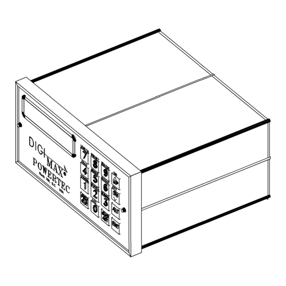
Page 10: Physical Dimensions
® Figure 1: Physical dimensions of the DIGIMAX Page 2 © copyright 1992-1996 by Powertec Industrial Motors... -
Page 11: 1.1 Customer Connections
DIGIMAX must be kept away from power wiring. ® ® ® ® ® All relays used in conjunction with, or in the vicinity of, the DIGIMAX must have arc ® suppressors (if they have AC coils) or free wheeling diodes (if they are DC). Keep high power... - Page 12 24 VDC output, unregulated, 100 mA NO CONNECTION NO CONNECTION DIGIMAX DIGIMAX If you have an application where you wish to use DC power to power a DIGIMAX DIGIMAX DIGIMAX ® you must either use a UPS or contact POWERTEC for a special unit.
-
Page 13: Rear Terminal Strip Connections
Figure 2: Rear terminal strip connections of the DIGIMAX DIGIMAX DIGIMAX DIGIMAX DIGIMAX ® common, but their emitters are all common to each other. The maximum allowable voltage between TB1 terminals 22 (+) and 14 (-) is 30VDC. The maximum allowable current on each of the TB1 terminals 15 thru 21 is 100 mA. - Page 14 It normally comes from the motor control, but it may come from any frequency reflecting the driven process. With a 1750 RPM small frame motor, a standard POWERTEC Brushless motor control supplies a 3500 Hertz pulsed waveform to this input, but larger motors' controls supply a 7000 hertz signal to the tachometer input and servo rated controls may supply frequencies of up to 50 kilohertz.
- Page 15 (+ to +, and - to -). ANSI standards apply to RS-422 communications. The RS-422 standard stipulates that the number of stations shall be at least 10 without repeaters. (Repeaters are amplifiers which strengthen the signal to feed more stations). The DIGIMAX DIGIMAX DIGIMAX...
-
Page 16: Connections To The Digimax
Figure 3: Connections to the DIGIMAX speed controller. ® Page 8 © copyright 1992-1996 by Powertec Industrial Motors... - Page 17 TION TION 2.0 ORIENT 2.0 ORIENT TION ® The proper operation of the DIGIMAX DIGIMAX DIGIMAX DIGIMAX DIGIMAX requires a complete understanding of the front panel controls. Speeds, ratios, and parameters will be set by the operator with the keypad, which consists of numerical and action keys.
- Page 18 "A" characters (hex 41) on the RS-422 port for 10 seconds. This function is used for testing. It is accessed by pressing the ALT key followed by the "1" key. SFWVER To accommodate changes in function of the DIGIMAX , the software in the ®...
- Page 19 Pressing ALT followed by the "3" key displays the serial number of the unit. DIAG The DIAGnostics function will display a set of diagnostic aids to help to determine DIGIMAX DIGIMAX the state of the DIGIMAX DIGIMAX DIGIMAX . You must have a knowledge of how to use hexadecimal numbers ®...
- Page 20 In Remote mode only the REM/LCL function and the COM/ ACT key will operate. If parameter #19 is set to "2" (KEYLOCK), you must press the ALT key, DIGIMAX DIGIMAX an access code, the UP key and the ENT key in sequence before the DIGIMAX DIGIMAX DIGIMAX will switch ®...
-
Page 21: 3.0 Set Up Parameters
If it is part of a system, it will be shipped with parameters which will be set up according to the information which POWERTEC has available about how it will be used. If a special setup has been requested, or is required, that is how it is shipped. Table I on page... -
Page 22: Maximum Motor Speed
Software version 93166. DIGIMAX DIGIMAX Table I: Parameter table for the DIGIMAX DIGIMAX DIGIMAX . Default values are the values used for basic testing. Values used in a particular ® application may be entered in the VALUE column. Page 14... - Page 23 Speed and ratios may be entered from the comm link. Speeds and ratios may be entered while stopped. They will be entered and registered, but they will not show up in the COMMAND mode display until the DIGIMAX DIGIMAX...
-
Page 24: Slave Ratio Setting
If there is a doubt as to either the encoder PPR or the EPROM multiplier, check the motor for a special (external) encoder, then follow this procedure : If there is no special encoder, make sure that the default parameters are installed in the first eight parameters of the DIGIMAX DIGIMAX DIGIMAX... -
Page 25: Master/Slave
MASTER/SLAVE MASTER/SLAVE Valid values are 0, 1, or 2. See page 32 for more information. Enter 0 for MASTER mode. In MASTER mode, the DIGIMAX generates a train of ® pulsesbased on the SETPOINT and parameter #5, limited by parameter #1. The frequency, during ramping periods, is also modified by parameters #6 and #7. -
Page 26: Jump Down Change
FLOAT / FREEZE FLOAT / FREEZE Valid values are 0 or 1. This parameter may be changed while running. If this parameter is set to 0, the SETPOINT is lost when the DIGIMAX is stopped. If ® this parameter is set to 1, the SETPOINT value is stored in non-volatile memory and is retained while the motor is stopped. -
Page 27: Unit I.d
600), 12 (for 1200), 24 (for 2400), 48 (for 4800) and 96 (for 9600). After setting the baud rate, the serial communications of the host must be set to 8 data bits, NO parity, and 1 stop bit (8-N-1). These settings in the DIGIMAX DIGIMAX... -
Page 28: To D High Engineering Units
0..255 AT SPEED Source 0 to 1 Comm Turn-Around Time 0 to 255 Table 1A: Additional parameters for the DIGIMAX ® #23 A TO D HIGH ENGINEERING UNITS A TO D HIGH ENGINEERING UNITS A TO D HIGH ENGINEERING UNITS... -
Page 29: Maximum Ratio
(parameter #9). When a "0" is entered in this parameter, that is the case. When a "1" is entered, it becomes a general purpose input (subject to software). When a "2" is entered, it puts the DIGIMAX DIGIMAX DIGIMAX DIGIMAX into a dual setpoint mode. -
Page 30: Reverse Input Mode
MINIMUM COMMAND RATIO This parameter sets the minimum value a ratio is allowed to accept. Valid values are DIGIMAX DIGIMAX ® from 0.0000 to 7.9999. If a lower ratio is entered, the DIGIMAX DIGIMAX DIGIMAX generates error 21. #39 DEBOUNCE VALUE... -
Page 31: Local Or Remote
Whether MOP or JUMP mode is needed. Where and how the SETPOINT is to be entered. Whether an RS-422 communications link is to be used. After this information has been gathered, it is relatively easy to program the DIGIMAX DIGIMAX DIGIMAX... - Page 32 Figure 5: Typical connections of the DIGIMAX to a POWERTEC Model 500 Brushless DC control. ® Page 24 © copyright 1992-1996 by Powertec Industrial Motors...
-
Page 33: Command Or Actual
TB1 terminals 17 through 21 which may be used by the host computer to control relays for these DIGIMAX DIGIMAX ® functions, so it is possible to control the DIGIMAX DIGIMAX DIGIMAX entirely through the RS-422 port. SETUP OR NORMAL... - Page 34 Figure 6: Typical connections to a POWERTEC Non-Regenerative Brushless DC control. Page 26 © copyright 1992-1996 by Powertec Industrial Motors...
-
Page 35: Error Codes
DIGIMAX ® ERROR CODES ERROR CODES ERROR CODES ERROR CODES ERROR CODES During parameter entry, mistakes may be made. The DIGIMAX DIGIMAX DIGIMAX DIGIMAX monitors the input DIGIMAX ® values, and if the value is proper for the current parameter or mode of operation, the value will be accepted and the parameter table changed. - Page 36 Figure 7: Standard connections to a POWERTEC Regenerative Brushless DC control. Page 28 © copyright 1992-1996 by Powertec Industrial Motors...
- Page 37 VALUE GREATER THAN 99999 This error may occur in any entry. Although you can't enter a number greater than ® 99999, for some reason the DIGIMAX may think you did. Press ENTER to clear the error and reenter the parameter.
- Page 38 Figure 7: Standard connections to a POWERTEC MILLENNIUM Brushless DC motor control. ® Page 30 © copyright 1992-1996 by Powertec Industrial Motors...
-
Page 39: Jump Or Mop
Parameter # 13 (page 18) Parameter # 10 (page 17) Parameter # 11 (page 18) JUMP -- Pressing the UP button or activating the UP input (TB2 terminal 9) causes the ® output of the DIGIMAX DIGIMAX DIGIMAX DIGIMAX DIGIMAX to increase by the amount set in parameter #10. -
Page 40: Master Or Slave
MASTER OR SLAVE MASTER OR SLAVE MASTER OR SLAVE Parameter #8 (page 17) Parameter #4 (page 16) ® When a 0 is entered into parameter #8, the DIGIMAX DIGIMAX DIGIMAX DIGIMAX DIGIMAX is in the MASTER MODE. The MASTER mode generates its own frequency from the parameters and SETPOINT given. -
Page 41: Basic Master Mode Setup
MOP mode. The operator is the only one authorized to make any changes, and you give him his birthdate (2/14/52) as a security code. Press [PGM] (code) [ENT]. The DIGIMAX will flash P-1 and the current value. If the flashing ®... -
Page 42: Basic Slave Mode Setup
Enter a 1 in P-13 for MOP operation. Press the UP button. Enter a 1 in P-14 to make the DIGIMAX IV go to ratio on start. Press the UP button.15. Enter 1 in P-15 for a 1 second update. Press the UP button. -
Page 43: Advanced Functions
When switching from SLAVE to MASTER, the DIGIMAX will use as a SETPOINT the speed ® at which it is currently running. When switching from MASTER to SLAVE, the DIGIMAX will ® look to parameter #37 for its setpoint. The default of parameter #37 is 0.0000! If you do not... - Page 44 Page 36 © copyright 1992-1996 by Powertec Industrial Motors...
- Page 45 ® them for process or set-up purposes. To give unlimited access to the parameters is to invite disaster. There are two ways to attain entry into the DIGIMAX DIGIMAX DIGIMAX...
- Page 46 Page 38 © copyright 1992-1996 by Powertec Industrial Motors...
Need help?
Do you have a question about the Digimax and is the answer not in the manual?
Questions and answers