
Related Manuals for Cembre LD-16B


Summary of Contents for Cembre LD-16B
- Page 1 RAIL DRILL LD-16B - LD-16BA - LD-16BE - LD-16BT ENGLISH OPERATION AND MAINTENANCE MANUAL...
-
Page 2: Table Of Contents
12.1) Drill fi tted with broach cutter ..........................26 12.2) Drill fi tted with spiral bit ............................28 Alarms....................................29 SPA positioning plate ..............................30 Storing the drill ................................32 Maintenance .................................. 33 Cembre Return to for overhaul..........................35 Appendix “A” ....................................35... - Page 3 – Do not use the rail drill for purposes other than those intended by Cembre. – Never use a rail drill that is faulty, has been tampered with or which has been modifi ed from its original form.
- Page 4 Unlawful disposal of such equipment will be subject to the application of administrative sanctions provided by current legislation. Defi nitions: LD-16BN LD-16BNA LD-16BNE LD-16BNT (drill without railweb clamping device) LD-16B LD-16BA LD-16BE LD-16BT (drill complete with DBG-F2 railweb clamping device)
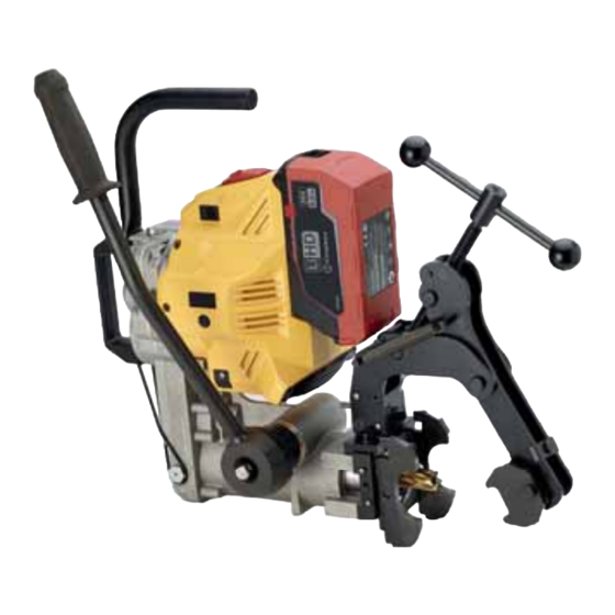
- Page 5 Descriptions: FIG. 1 Powerful LED worklights Spindle advance lever Battery 36V Li-Ion Trasport handle Oil fi ller cap 36V DC motor unit Oil level indicator Coolant connection Cap with magnetic insert Lubricator for spindle shaft Front plate for assembling templates Spindle shaft Support handgrip LED indicator...
-
Page 6: General Characteristics
(9/32) (1 5/16) Rated drilling capacity Ø mm (inch) 7 13 (9/32) (1/2) with Cembre PE range spiral bits 13 33 (1/2) (1 5/16) with Cembre CY range broach cutters Max drilling thickness mm (inch) 50 (2) -
Page 7: Accessories Supplied With The Drill
2. ACCESSORIES SUPPLIED WITH THE DRILL 2.1) Guide bits for controlling the coolant system: for broach cutters suitable for drilling thickness up to 25 mm PP 1 (1 pc) diameter 7 mm. PP 2 (1 pc) diameter 8 mm. for broach cutters suitable for drilling thickness up to 50 mm PPL 1 (1 pc) diameter 7 mm. - Page 8 2.11) Type SR5000 coolant unit (1 pc) Provides coolant fl uid to the cutter during the drilling operation. Consists of a tank complete with tube and maximum pressure valve, fi tted with a pump device for pressurisation. 2.12) Type CB3662L rechargeable battery (2 pcs) 36 V 6,2 Ah (LiHD Technology) Li-Ion, equipped with LED indicators of the remaining battery life at any time by pressing the button.
-
Page 9: Accessories To Be Ordered Separately
TDB 6: – standard termination for rails and stock rails. (*) Already supplied with LD-16B ; LD-16BA ; LD-16BE ; LD-16BT rail drills 3.1.1) DBG-LF2 device TDB 7 with moving arm complete with... - Page 10 – MPAF UIC54 on DRILLING AXIS of 54E1 rail – MPAF UIC60 on DRILLING AXIS of 60E1 rail • Contact Cembre for selection of other specifi c application accessories. 3.5) MPAU universal positioning template suitable for repairing existing holes on various fi...
- Page 11 CY300L CY310 CY320 CY320L CY330 CY330L MAX DRILLING THICKNESS MAX DRILLING THICKNESS 25 mm 50 mm CY broach cutters allow automatic cooling by means of the SR5000 unit supplied with the drill. Contact Cembre for other types of broach cutters.
- Page 12 3.11) PE range spiral bits and adapters APED... APE... L max SPECIAL SPIRAL BITS FOR RAILS IN STEEL QUALITY 700 900 1100 UIC 860.0 Ø Required Spiral adapter PE70 APED70 PE71 PE80 APED80 PE85 PE90 APE 90 PE95 APE 95 PE100 APE100...
-
Page 13: Spindle Advance Lever
4. SPINDLE ADVANCE LEVER The spindle is advanced by moving the lever (36) (Ref. to Fig. a). The lever is fi tted with a release pawl (39) (Ref. to Fig. b). which, when pressed, renders it independent of the hub and hence the spindle;... -
Page 14: Motor On/Off Switch (Emergency)
5. MOTOR ON/OFF SWITCH (EMERGENCY) The motor switch (15) is placed on the motor in an easily visible position and can be rapidly activated in case of emergency. It is a tilt switch and provided with an interlock device to avoid unintentional start-ups. The switch has two specifi... -
Page 15: Led Indicator
(Ref. to § 13). 8. "DRILLING ASSISTANCE" FUNCTION The “drilling assistance” function has been developed and optimised for use with Cembre CY range Broach Cutters (diameter from19 to 32 mm, ref. to § 3.10), on 800 and 900 quality steel rails (UIC 860.0). -
Page 16: Rechargeable Battery
9. RECHARGEABLE BATTERY Batteries are supplied with a charge ≤ 30%. To maximise energy level, it is necessary to fully recharge them before use. Only use the battery charger supplied with the drill. Charge the battery by following the instructions provided in the battery charger manual, approximately 50-60 minutes are required to charge a fully depleted battery with ASC ULTRA fast charger. -
Page 17: Sr5000 Coolant Unit
Connect the SR5000 coolant unit to the attachment (35) on the drill by means of its quick-coupling (03) by passing the hose through the O-Ring (36) so as to support the tap (02). The use of the lubrocoolant supplied by Cembre, in the recommended concentrations, guarantees optimum life of the cutting tools. - Page 18 The drill is equipped with a coolant attachment valve (35) and a vent valve (17). If under certain operating circumstances they need to be interchanged, proceed as follows: Using a 17 mm spanner unscrew the vent valve from its seat. Remove the protection plate and using the 4 mm T-handle Allen key provided with the drill, remove the appro- priate coolant valve from its seat and fi...
-
Page 19: Preparing The Drill
Be careful of the broach cutter’s sharp edges. Always wear work gloves to avoid injury. The drill spindle is factory-set to operate with Cembre CY range broach cutters fi tted with Quick push/turn coupling; use of broach cutters and twist drill bits fi tted with Weldon shank only requires disassembly of the transverse pin in the spindle (Ref. -
Page 20: Assembling Broach Cutters With Weldon Shank
11.2) Assembling broach cutters with Weldon shank Using the spindle lever, advance the spindle to make the transverse threaded pin accessible; if it is not in a easily-accessible position, insert the battery and slide the Motor switch forward (index- ing function (Ref. to § 5) to make the pin visible, then remove the battery. -
Page 21: Assembling Spiral Bits
11.3) Assembling special spiral bits Using the spindle lever, position the spindle shaft so that both grub screws (18) become accessible. If necessary, insert the battery, slide the Motor switch forward to generate successive rotations of the spindle (indexing function (Ref. to § 5), making the grub screws (18) visible, then remove the battery. Insert the spiral bit in the corresponding APED adapter (1) and lock it with the grub screw (19) using the 4 mm T-handle Allen key (2) (Ref. -
Page 22: Assembling Terminations On Dbg-F2 Clamping Device
11.4) Assembling terminations on DBG-F2 clamping device TDB 1, TDB 6 and TDB 3 terminations of the DBG-F2 device, with moving arm, have been designed for adaptation to the diff erent operating conditions on rails and track fi ttings; their assembly/disassembly is shown in the Figures. Normally they are mounted in the central holes of the clamping device. -
Page 23: Assembly Of Dbg-F2 Clamping Device
11.6) Assembling positioning templates Only Cembre positioning templates and jigs are to be used with the rail drill. Choose the correct positioning template for the rail profi le to be drilled. Place the positioning template on to the front plate of the drill, aligning the two reference pins with the holes in the template. -
Page 24: Fitting "Double-Sided" Templates
11.7) Fitting “double-sided'” templates Compared to the templates for positioning rail drills, the KPAF "double-sided templates" are equipped with a double profi le that enables positioning of the drill on two diff erent types of rail by simply inverting them. They are fi... -
Page 25: Clamping The Drill To The Rail Web
11.8) Clamping the drill to the rail web The drill has a rapid rail engagement/release mechanism and specially shaped positioning templates for each rail type which facilitate precise and certain location of the part to be drilled. To fully exploit the special features of the engagement device, we recommend calibrating it to the rail type to be drilled as follows: Withdraw the spindle shaft (07) completely by means of the lever (36). -
Page 26: Drilling Operation
12. DRILLING OPERATION To optimise battery charge and for safety reasons, the drill is equipped with a timer. If drilling operations continue for more than 120 seconds, the motor automatically stops. To re-start it, it is suffi cient to operate the Motor switch. max.120 s Switch on the cooling system before starting the drill (§... - Page 27 5) Start the machine by pressing the Motor switch (15) as described in the § 5. If necessary, activate switch (16) for the automatic illumination of the LED worklights. Green LED illuminated 6) Proceed to drill the hole by initially applying a light pressure on the lever, gradually pushing it so that the green LED on the indicator display turns on (Ref.
-
Page 28: Drill Fi Tted With Spiral Bit
Approach Start drilling with discharge of lubrocoolant Drilling Finish drilling with removal of swarf and switching off of lubrocoolant The slug is ejected upon completion of Clean the spindle and the broach cutter of any swarf with the brush provided. the drilling operation Ensure that swarf is removed before carrying out another drilling process. -
Page 29: Alarms
YELLOW - Self diagnosis with a negative out - If the problem persists, please contact Cembre. come. (*) If the battery overheats, it is possible to insert it into the supplied battery charger, making use of the specifi c “AIR COOLED” function in order to make it cool down quicker. -
Page 30: Spa Positioning Plate
14. SPA... POSITIONING PLATE 14.1) Drilling close to rail heads FIG. a MPAF Fit the MPAF... positioning template corresponding to the rail to be drilled. 2) Insert the SPA... positioning plate (03) relating to the rail to be drilled, in the appropriate housing (Ref. to Fig. a). 3) Insert the locking pin (02) in one of the two holes in the positioning plate. - Page 31 14.2) Drilling in line with rail heads 1) Fit the MRF clamp on the head of the rail (Ref. to Fig. d). keeping it in contact with the rail head at the reference point of the drilling centres. Lock it in position with the lever. The lever is provided with a return push-button for moving in any direction after locking.
-
Page 32: Storing The Drill
The optimum storage temperature of the batteries is between 10 ° C and 30 ° C. For better protection Cembre recommends the use of the VAL P24 or VAL P24-CS (with wheels) plastic cases de- signed for this purpose, which enable to store the drill blocked by means of the DBG-F2 clamping device and canvas bags for batteries and battery charger. -
Page 33: Maintenance
The maintenance procedures described may be carried out by the operator. For any eventual fi ne tuning or repairs, return to Cembre (Ref. to § 17). 16.1) ORDINARY MAINTENANCE OF THE DRILL Daily Before use, check: The drill in its entirety (securing of various components). - Page 34 Every 20 hours of operation 16.1.1) Check screws Check and re-tighten all screws where necessary. 16.1.2) Top up oil With the drill placed on a fl at surface, check the oil level in the crankcase by looking through the appropriate transparent in- spection cover (13).
-
Page 35: Return To Cembre For Overhaul
Centre; if possible, attach a copy of the Test Cer- tifi cate supplied by Cembre together with the machine or fi ll in and attach the form available in the “ASSISTANCE”... - Page 40 Tel.: 01675 470440 - Fax: 01675 470220 CS 92014 - 91423 Morangis Cédex E-mail: sales@cembre.co.uk E-mail: info@cembre.fr www.cembre.co.uk www.cembre.fr Cembre España S.L.U. Cembre GmbH Calle Verano 6 y 8 Heidemannstraße 166 28850 Torrejón de Ardoz - Madrid (España) 80939 München (Deutschland) Teléfono: 91 4852580...
Need help?
Do you have a question about the LD-16B and is the answer not in the manual?
Questions and answers