
Related Manuals for Cembre LD-41PY


Summary of Contents for Cembre LD-41PY
- Page 1 08 M 076 U ENGLISH Cer fied Quality Cer fied Environmental Cer fied Occupa onal Management System Management System Health & Safety Management System RAIL DRILL LD-41PY TYPE OPERATION AND MAINTENANCE MANUAL...
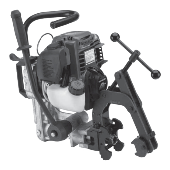
- Page 2 – Always wear protective glasses and work gloves. – Avoid wearing clothes which may present a risk to personal safety. – Always check combustion engine oil level before operation! LD-41PNY basic drill LD-41PY (LD–41PN + DBG-Y) basic drill complete with railweb clamping device...
- Page 3 1. RAIL DRILL TYPE LD-41PNY GENERAL CHARACTERISTICS The Cembre LD-41PNY drill powered by HONDA 4-cycle engine can be stored and continuously op- erated in full 360° inclination, thanks to the rotary-slinger pumping lubrication system. – Drilling capacity:........................Ø 9/40" to 1 9/16"...
-
Page 4: Accessories Supplied With The Drill
2. ACCESSORIES SUPPLIED WITH THE DRILL 2.1) Pilot bits for controlling the cooling system: for use with short broach cutters (7/8 " depth of cut) – 1 pc PPC 2 for use with long broach cutters (2 " depth of cut) –... -
Page 5: Optional Accessories (To Be Ordered Separately)
fi ttings, complete with the TDB 6 termination. Always supplied with drilling machine ref. LD-41PY 3.1.1) "DBG-LY" device specifi c for clamping the drill to the girder rails (for example 128 GR or GGR 118). With the specifi c shoes allows the positioning on both sides of the rails, complete with theTDB 3 termination. - Page 6 3.2) “VAL P24” plastic carrying case for storing the drill complete with the device with moving arm and accessories. Also available VAL P24-CS plastic carrying case with folding handle and wheels. 3.2.1) “VAL LD-L” metal case for storing the drill complete with the DBG-LF2 device, and VAL MPA tool case.
- Page 7 Suitable for positioning the drill on running and guard rails Enable the automatic position of the machine onthe drilling axis (H) of each specifi c rail. • Note: Please contact Cembre for other types of rail. RAIL SHOES DRILLING ON RUNNING RAILS TYPE OF RAIL RAIL inch...
- Page 8 3.6) JOINT BAR POSITIONING GAUGES Positioning gauges MRF-Y... for drilling joint bar holes at pre-defi ned distances between rail end and holes center lines. RAIL END AIL END HOLES DISTANCES (inch) POSITIONING GAUGE 2 21/32" 7 1/4" 5 1/2" MRF Y10 3 1/2"...
- Page 9 3.7) BROACH CUTTERS These cutters rapidly produce high quality, accurate holes in a single pass. The automatic lubrocooling system reduces friction and eliminates heat build up during the drilling operation. Un- der standard conditions a broach cutter can drill 40-50 holes, depending on the hardness of the rail.
- Page 10 3.8) SPECIAL SPIRAL TWIST BITS Using these bits guarantees optimum performance during the drilling operations. As a rule, under normal conditions, a spiral bit can drill 70-100 holes, depending on the hardness of the rail. with adapter APED... without adapter HOLE SPIRAL ADDITIONAL...
- Page 11 fl uid must be eff ected manually by operating the tap (02). The use of the lubrocoolant supplied by Cembre, in the recommended concentrations, guarantees optimum use of the drilling tools. Consumption of the lubrocoolant depends both on the variable degree of opening of the tap (02) and the inner pressure of the tank: it is therefore advisable to open the tap a little when the tank is at maximum pressure, while it must be fully opened when the pressure in the tank is low.
- Page 12 • The drill is equipped with a coolant attachment valve (35) and a vent valve (17) which are located as shown (Fig. 3). If under certain operating circumstances they need to be interchanged, proceed as follows: – Using a 17 mm hexagonal spanner unscrew the vent valve from its seat. –...
- Page 13 5. SPINDLE ADVANCE LEVER (Ref. to Fig. 6) The spindle is advanced by moving the lever (36) (See Fig. 6 a). The lever is fi tted with a release pawl (39) which, when pressed, ren- ders it independent of the hub and hence the spindle;...
-
Page 14: Preparing The Drill
6. PREPARING THE DRILL 6.1) Assembling broach cutters (Ref. to Figs. 8-11). 6.1.1) Insert the pilot bit in the cutter from the side of the spigot. 6.1.2) Using the lever (36), position the spindle shaft (07) so that both grub screws (18) become accessible and suffi... - Page 15 6.2.2) Insert into the spindle shaft, the DPE spacer required to activate the coolant system. If it necessary to use an APE... adaptor, the bit must fi rst be fi tted into the corresponding APE adaptor and locked with the appropriate grub screw, then the DPE spacer inserted. Note: Adaptors type APED…...
- Page 16 7. RAIL DRILL TYPE LD-41PY Ref. LD-41PY consist of the LD-41PNY basic drill (see page 2) complete with the DBG-Y moving arm device for clamping to the rail web and the track fi ttings (Refer to Fig. 12). The DBG-Y clamping device consists of: –...
- Page 17 7.1) Assembling of the termination of the DBG-Y device with moving arm for clamping the drill to the rail web and track fi ttings. The termination TDB 6 of the DBG-Y device, with moving arm, have been designed for adaptation to the diff...
- Page 18 DBG-Y Clamping device FIG. 14 – ASSEMBLY OF DBG-Y CLAMPING DEVICE Rail drill front plate 7.3) Assembly of positioning shoes (Ref. to Fig. 15) 7.3.1) The type MPAF.. and MPAU positioning shoes are secured to the front plate (22) of the drill by means of the two socket head cap screws M 6x16 supplied.
- Page 19 7.4) Clamping to the rail web (Ref. to Fig. 16) The special shape of the positioning shoes, each corresponding to the type of rail, enables the drill to be positioned quickly, accurately and safely on the element to be drilled. To position the drill, complete with the clamping termination (§...
- Page 20 8. DRILLING (Ref. to Figs. 17-18) Check engine oil level before operation (see § 13.2.4) Switch on the cooling system before starting the drill (see § 4) 8.1) Drill fi tted with “short” type broach cutter (for drilling thicknesses of up to 1"). The drilling sequence may be started with the drill fi...
- Page 21 8.1.4) Start the engine, following instructions on § 11. 8.1.5) Proceed to drill by initially applying light pressure on the lever (36), increasing the pressure progressively, avoiding jolts, and fi nally relieving the pressure in the exit phase. When drilling close to raised markings on the rail the initial pressure must be extremely light until the markings disappear, otherwise the cutter may be damaged.
- Page 22 Approach Start drilling with discharge of lubrocoolant Drilling Finish drilling with removal of swarf and switching off of lubrocoolant FIG. 19 – COOLANT DRILLING WITH BROACH CUTTER 8.3) Drill fi tted with special spiral bit Follow the sequence described in (§ 8.1), taking care to position the drill on the rail by keeping the spindle fully withdrawn.
- Page 23 (narrow passage of the articulated arm) DBG-GR over rail clamp equipped with TDB1 termination FIG. 22 10. SPECIAL APPLICATIONS FOR Cembre RAIL DRILLS MPAF 85 LB ASCE = Application developed for narrow chairs 1 = For drilling 56 lb aluminium bar manufactered by FOSTER...
-
Page 24: Start Engine
11. START ENGINE Before starting the engine, ensure that: - the spindle shaft is fully retracted. - the accelerator control lever is positioned at the low speed position. 11.1) Set the engine “ON/OFF” switch to the “ON” position (Fig. a). 11.2) Set the choke lever to the CLOSED position;... -
Page 25: Check Fuel
- To avoid a serious burn, do not touch a hot engine or muffl er. - The engine becomes hot during operation. The LD-41PY drilling machine features a 4-CYCLE gasoline engine run on unleaded regular gas- oline only. Pump octane rating 86 or higher. - Page 26 13.4) Place the drill and the SR5000 coolant unit in a sealed place free from dust, moisture and the risk of accidental impact. For better protection Cembre recommends the use of the VAL P24 plastic case or VAL P24-CS (variant with folding handle and wheels, see Fig. 24a) designed for this purpose (see § 3.2). The h folding DBG-Y moving arm device allows the drill to be housed and locked in the case.
-
Page 27: Maintenance
14. MAINTENANCE Before you service or remove parts, stop the engine and allow it to cool. Always remove the cap from the spark plug when servicing the engine to prevent acci- dental starting. After the fi rst 10 operating hours, proceed with sump oil change, as follows: (Ref. - Page 28 14.1.2) Removal of metal residues from the crankcase When the drill is positioned as shown in Fig. 25unscrew the cap with magnetic insert (28) on which any metal residues present in the oil will have collected. Carefully clean the magnetic insert with a clean cloth and screw it back into the appropriate housing.
- Page 29 14.2 ORDINARY MAINTENANCE OF THE COMBUSTION ENGINE Periodic inspections are essential for the proper functioning of the engine; refer to "HONDA" manual provided with the machine for the safe use of the engine and for further requested maintenance operations. Every 100 hours of operation 14.2.1) Fuel fi...
- Page 30 Every year or 100 hours of operation 14.2.3) Spark plug cleaning (Ref. to Fig. 29) – Using a 4 mm allen key remove the fi xing screw on the top of the red cover. – Disconnect the spark plug wire lead and remove the spark plug with the key supplied. Inspect the spark plug.
- Page 31 14.2.5) Engine oil change (Ref. to Figs. 30 and 31) Initial oil change: fi rst month or after 10 hours of operation Thereafter: every 6 months or 50 hours of operation – Drain the used oil when the engine is warm. Warm oil drains quickly and completely. –...
- Page 32 Guarantee conditions cease upon usage of non original spare parts. When ordering spare parts always give the following information: - spare part code - spare part description - drilling machine model - drilling machine serial number FIG. 32 – LD-41PNY DRILL ASSEMBLY...
- Page 33 Starting handgrip 6001209 Magnetic cap Engine 6900060 M 4x8 screw Air fi lter element 6001731 Cooling connection guard 6003476 Spark plug 6001198 Lubricator Handle 6002607 Front plate 6380330 6002613 Complete handgrip 6002602 Drilling spindle 6001166 Accelerator lever 6001397 Complete air valve 6003034 6340160 M 8 x 10 grub screw...
-
Page 35: Return To Cembre For Overhaul
Centre; if possible, attach a copy of the Test Certifi cate supplied by Cembre together with the tool or fi ll in and attach the form available in the “ASSISTANCE” section of the Cembre website. - Page 36 CS 92014 – 91423 Morangis Cédex E-mail: sales@cembre.com E-mail: sales@cembre.co.uk E-mail: info@cembre.fr www.cembre.it www.cembre.co.uk www.cembre.fr Cembre España S.L. Cembre GmbH Cembre Inc. Calle Verano, 6 y 8 - P.I. Las Monjas Heidemannstraße 166 Raritan Center Business Park 28850 Torrejón de Ardoz - Madrid (España) 80939 München (Deutschland)
Need help?
Do you have a question about the LD-41PY and is the answer not in the manual?
Questions and answers