Table of Contents
Advertisement
Quick Links
www.cembre.com
Cembre S.p.A.
Cembre Ltd.
Via Serenissima, 9
Dunton Park
25135 Brescia (Italia)
Kingsbury Road, Curdworth - Sutton Coldfield
Telefono: 030 36921
West Midlands B76 9EB (Great Britain)
Telefax: 030 3365766
Tel.: 01675 470440 - Fax: 01675 470220
E-mail: info@cembre.com
E-mail: sales@cembre.co.uk
www.cembre.it
www.cembre.co.uk
Cembre España S.L.
Cembre AS
Calle Verano, 6 y 8 - P.I. Las Monjas
Fossnes Senter
28850 Torrejón de Ardoz - Madrid (España)
N-3160 Stokke (Norway)
Teléfono: 91 4852580
Phone: (47) 33361765
Telefax: 91 4852581
Telefax: (47) 33361766
E-mail: info@cembre.es
E-mail: cembre@cembre.no
www.cembre.es
www.cembre.no
Cembre S.a.r.l.
22 Avenue Ferdinand de Lesseps
91420 Morangis (France)
Tél.: 01 60 49 11 90 - Fax: 01 60 49 29 10
B.P. 37 - 91421 Morangis Cédex
E-mail: info@cembre.fr
www.cembre.fr
Cembre GmbH
Cembre Inc.
Heidemannstraße 166
Raritan Center Business Park
80939 München (Deutschland)
181 Fieldcrest Avenue
Telefon: 089/3580676
Edison, New Jersey 08837 (USA)
Telefax: 089/35806777
Tel.: (732) 225-7415 - Fax: (732) 225-7414
E-mail: info@cembre.de
E-mail: Sales.US@cembreinc.com
www.cembre.de
www.cembreinc.com
Certified Quality
Certified Environmental
Management System
Management System
RAIL DRILL
TYPE
LD-2EY
OPERATION AND MAINTENANCE
MANUAL
07 M 053 U
ENGLISH
Certified Occupational
Health & Safety
Management System
Advertisement
Table of Contents

Related Manuals for Cembre LD-2EY


Summary of Contents for Cembre LD-2EY
- Page 1 B.P. 37 - 91421 Morangis Cédex E-mail: info@cembre.com E-mail: sales@cembre.co.uk E-mail: info@cembre.fr MANUAL www.cembre.it www.cembre.co.uk www.cembre.fr Cembre España S.L. Cembre AS Cembre GmbH Cembre Inc. Calle Verano, 6 y 8 - P.I. Las Monjas Fossnes Senter Heidemannstraße 166 Raritan Center Business Park 28850 Torrejón de Ardoz - Madrid (España)
-
Page 2: Table Of Contents
6. Preparing the rail drill ...................13 7. Rail drill type LD-2EY ..................15 8. Drilling ........................19 9. Example of other rail drill applications ..............22 10. Special applications for Cembre rail drills ............22 11. Storing the rail drill ....................23 Ref. LD-2EY: Ref. LD-2EYGR: 12. -
Page 3: Rail Drill Type Ld-2Eny
NOTES ATTENTION – Before using the rail drilling, carefully read the instructions contained in this manual. SAVE THESE INSTRUCTIONS: this manual contains important safety and operating instructions for the drilling machine. – The degree of protection of the drilling machine against moisture is classifi... -
Page 4: Accessories Supplied With The Rail Drill
2. ACCESSORIES SUPPLIED WITH THE RAIL DRILL 2.1) Pilot bits for controlling the cooling system: for use with short broach cutters (7/8 " depth of cut) – 1 pc PPC 2 for use with long broach cutters (2 " depth of cut) –... -
Page 5: Optional Accessories (To Be Ordered Separately)
3.1) "DBG-Y" device with moving arm for clamping the rail drill to the rail web and track fi ttings, complete with the TDB 6 termination. * Always supplied with rail drill ref. LD-2EY TDB 6 3.1.1) "DBG-LY" device specifi c for clamping the rail drill to the girder rails (for example 128 GR or GGR 118). - Page 6 3.2) "TST 50" two stage template (to be used with specifi c DBG-AY clamp) This device enables the drilling of 150 lb and alu- minium composite contact rails from one side. Restart of work stroke: 1,97” Typical application: – Aluminium composite rail. –...
- Page 7 (H) of each specifi c rail. and give you the necessary instructions on how to dispatch the tool to our nearest service Centre; if possible, attach a copy of the Test Cerifi cate supplied by Cembre together with • Note: Please contact Cembre for other types of rail.
- Page 8 96,6 dB (A) Protection of operators against risksof exposure to noise during work. Cembre drills type LD-2EY are designed and constructed according to EEC directives 80/1107 and 86/188 relating to the protection of operators against risks arising from ex-...
- Page 9 3.7) BROACH CUTTERS These cutters rapidly produce high quality, accurate holes in a single pass. The automatic lubrocooling system reduces friction and eliminates heat build up during the drilling operation. Under standard conditions a broach cutter can drill 40-50 holes, depending on the hardness of the rail.
- Page 10 3.8) SPECIAL SPIRAL TWIST BITS Every 50 hours of operation Using these bits guarantees optimum performance during the drilling operations. As a 13.1.3) Checking the bolts rule, under normal conditions, a spiral bit can drill 70-100 holes, depending on the hard- Check and retighten all bolts.
-
Page 11: Type Sr5000 Coolant Unit
fl uid must be effected manually by operating the tap (02). – Remove the cap with the magnetic insert (21). The use of the lubrocoolant supplied by Cembre, in the recommended concentrations, – Remove oil fi ller cap (07). - Page 12 ● The drill is equipped with a coolant attachment valve (35) and a vent valve (17) which are located as shown (Fig. 3). 12. WARNINGS If under certain operating circumstances they need to be interchanged, proceed as follows: 12.1) Always disconnect the electrical supply when working on the drill to replace cutters, –...
-
Page 13: Spindle Advancing Lever
11.4) Place the rail drill and the SR5000 coolant unit in a sealed place free from dust, moisture and the risk of accidental impact. For better protection Cembre recommends the use of the VAL LD metal case designed for this purpose (see § 3.3). The DBG-Y moving arm device allows the drill to be housed 6a - Moving the lever (36) towards the operator;... -
Page 14: Preparing The Rail Drill
Drilling by the guard rail DBG-GR over rail clamp equipped with TDB 1 termination. FIG. 22 Pilot bit PPL 2 10. SPECIAL APPLICATIONS FOR Cembre RAIL DRILLS Long type broach cutter Maximum drilling thickness: 2" FIG. 8 – ASSEMBLING THE CUTTERS 6.2) Assembling the special spiral bits (Ref. - Page 15 6.2.2) Insert into the spindle shaft, the DPE spacer required to activate the coolant system. If it necessary to use an APE... adaptor, the bit must fi rst be fi tted into the corre Approach sponding APE adaptor and locked with the appropriate grub screw, then the DPE spacer inserted.
-
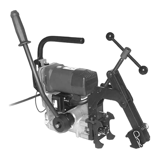
Page 16: Rail Drill Type Ld-2Ey
The reference LD-2EY relates to the entire LD-2ENY rail drill complete with the clamping device DBG-Y for clamping it to the rail web and the track fi ttings (Ref. to Fig. 12). -
Page 17: Drilling
7.1) Assembling of the termination of the DBG-Y device with moving arm for clamping 8. DRILLING (Ref. to Figs. 17 - 18 -19) the drill to the rail web and track fi ttings. The termination TDB 6 of the DBG-Y device, with moving arm, have been designed for Make sure that the mains voltage value corresponds to the value on the machine adaptation to the different operating conditions on the rails and track fi... - Page 18 7.4) Clamping to the rail web (Ref.to Fig. 16) The special shape of the positioning shoes, each corresponding to the type of rail, enables the drill to be positioned quickly, accurately and safely on the element to be drilled. To position the drilling machine, complete with the clamping termination (§ 7.1) and the DBG-Y Clamp positioning template (§...
Need help?
Do you have a question about the LD-2EY and is the answer not in the manual?
Questions and answers