Chapters
Table of Contents
Troubleshooting

Related Manuals for LS Industrial Systems iG5A


Summary of Contents for LS Industrial Systems iG5A
- Page 1 0.4~22kW(200V/400V) AC Variable Speed Drive iG5A Troubleshooting Manual Safety Instructions Read this manual carefully before servicing or inspecting this equipment. Keep this manual within easy reach for quick reference.
- Page 2 Quick Reference Table The following table contains situations frequently encountered by users while working with inverters. Refer to the typical and practical situations in the table to quickly and easily locate answers to your questions. Situation Reference The motor is too noisy. P.
-
Page 3: Table Of Contents
INTRODUCTION Manual Composition PRODUCT IDENTIFICATION ASSOCIATION MANUAL SAFETY INFORMATION REVISION RECORD Contents 1 BASIC CHECKLIST 1.1 Before You Think It Is Failure 1.2 Basic Operations 1.3 Parameter Change 1.3.1 Carrier Frequency Change 1.3.2 Initializing All Parameters 1.3.3 Read and Write Parameters 1.4 Fault Trip Monitoring 2 TROUBLESHOOTING... -
Page 4: Introduction
Introduction Manual Composition 1 Basic Checklist Basic Checklist 1.1 Before You Think It Is Failure When the problem of inverter occur, 1.2 Basic Operations you can check the basic checklist 1.3 Parameter Change before you think it is failure in these 1.3.1Carrier Frequency Change pages. -
Page 5: Product Identification
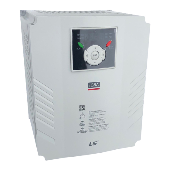
008-0.75kw 075-7.5kw 015-1.5kw 110-11.0kw 022-2.2kw 150-15.0kw 037-3.7kw 185-18.5kw 040-4.0kw 220-22.0kw Series name Input voltage 1- Single phase 200~230[V] 2- 3 phase 200~230[V] 4- 3 phase Association Manual iG5A user manual can be download through the homepage of LSIS. Link : http://www.lsis.com/support/download/... -
Page 6: Safety Information
Safety Information Read and follow all safety instructions in this manual precisely to avoid unsafe operating conditions, property damage, personal injury, or death. Safety symbols in this manual Danger Indicates an imminently hazardous situation which, if not avoided, will result in severe injury or death. Warning Indicates a potentially hazardous situation which, if not avoided, could result in injury or death Caution... - Page 7 Warning This equipment must be grounded for safe and proper operation. Do not supply power to a faulty inverter. If you find that the inverter is faulty, disconnect the power supply and have the inverter professionally repaired. The inverter becomes hot during operation. Avoid touching the inverter until it has cooled to avoid burns.
-
Page 8: Revision Record
Revision Record Changed main Version Date Association page contents V1.0 2015.03 First edition... -
Page 9: Basic Checklist
1 Basic Checklist 1.1 Before You Think It Is Failure Items Check Point Result Is the installation location appropriate? Installation Does the environment meet the inverter’s operating conditions? Location/ Input/Output Does the power source match the inverter’s rated input? voltage Is the inverter’s rated output sufficient to supply the equipment? Is a circuit breaker installed on the input side of the inverter? Is the circuit breaker correctly rated? - Page 10 Basic Checklist Items Check Point Result Are STP (shielded twisted pair) cables used for control terminal wiring? Is the shielding of the STP wiring properly grounded? If 3-wire operation is required, are the multi-function input terminals defined prior to the installation of the control wiring connections? Control Are the control cables properly wired? Terminal Wiring...
-
Page 11: Basic Operations
Basic Checklist 1.2 Basic Operations About the keypad The keypad is composed of two main components – the display and the operation (input) keys. Refer to the following illustration to identify part names and functions 7-Segment Display Displays current operational status and parameter FWD Indicator Display... -
Page 12: Operation Keys
Basic Checklist Operation Keys The following table lists the names and functions of the keypad’s operation keys. Name Description [RUN] Key Used to run the inverter (inputs a RUN command). [STOP/RESET] STOP: stops the inverter. RESET: resets the inverter following fault or failure condition. Switch between codes, or to increase or decrease parameter [▲] Key, [▼] Key values. -
Page 13: Parameter Change
Basic Checklist 1.3 Parameter Change 1.3.1 Carrier Frequency Change The following example demonstrates how to configure Carrier Frequency by modifying code H39(Carrier Frequency) in the Function group 2 from 5.00(Hz) to 10.00(Hz). You can configure the parameters for different codes in any other group in exactly the same way. Step Instruction Keypad Display... -
Page 14: Initializing All Parameters
Basic Checklist Adjust motor operational noise by changing carrier frequency settings. Power transistors (IGBT) in the inverter generate and supply high frequency switching voltage to the motor. The switching speed in this process refers to the carrier frequency. If the carrier frequency is set high, it reduces operational noise from the motor, and if the carrier frequency is set low, it increases operational noise from the motor. -
Page 15: Read And Write Parameters
Basic Checklist Step Instruction Keypad Display Press the [◀] key to move to the 10s place position. Press the [▲] or [▼] key to change the ‘0’ to ‘9’ of the target code, ’93.’ Press the [ENT] key. Code H 93 will be displayed. Press the [ENT] key once again. -
Page 16: Fault Trip Monitoring
Basic Checklist 1.4 Fault Trip Monitoring The following example demonstrates how to monitor fault trip conditions in the Operation group using the keypad. Over Current Trip Step Instruction Keypad Display Refer to the example keypad display. An over current trip fault has occurred. Press the [ENT] key, and then the [▲] key. - Page 17 Basic Checklist The following example demonstrates how to monitor fault trip record. Group Display Parameter Name Setting Range Default Unit [Fault history 1] Function group 2 [Fault history 5] [Reset fault history] 0 ~ 1 Up to 5 faults information is stored. a maximum of 5 fault trip records can be retrieved as shown in the following example.
- Page 18 Basic Checklist Frequency Current Fault types Fault during Accel Accel/Decel Fault during Decel Information Fault during constant run Reset fault record Change the value to ‘1’ and then press the [ENT] key.
-
Page 19: Troubleshooting
2 Troubleshooting This chapter explains how to troubleshoot a problem when inverter protective functions, fault trips, warning signals, or a fault occurs. If the inverter does not work normally after following the suggested troubleshooting steps, please contact the LSIS customer service center. 2.1 Trips and Warnings When the inverter detects a fault, it stops the operation (trips) or sends out a warning signal. -
Page 20: Fault/Warning List
2. Troubleshooting 2.1.1 Fault/Warning List The following list shows the types of faults and warnings that can occur while using the iG5A inverter. Category LCD Display Details Page Over current trip P. 21 ARM short current fault trip P. 22 Ground fault trip P. -
Page 21: Category Lcd Display
IOLT : IOLT(inverter Overload Trip) protection is activated at 150% of the inverter rated current for 1 minute and greater. OLT : OLT is selected when F56 is set to 1 and activated at 200% of F57[Motor rated current] for 60 sec in F58. This can be programmable. iG5A is not provided with “Over speed Protection.”... -
Page 22: Troubleshooting Fault Trips
2. Troubleshooting 2.1.2 Troubleshooting Fault Trips When a fault trip or warning occurs due to a protection function, refer to the following table for possible causes and remedies. LCD Display Type Description Over Displayed when inverter output current exceeds 200% of Latch Current the rated current. -
Page 23: Arm Short Current Fault Trip
2. Troubleshooting LCD Display Type Description Over Displayed when the DC circuit in the inverter detects a Latch Current2 specified level of excessive, short circuit current.. Cause Remedy Acc/Dec time is too short, Increase Acc/Dec time. compared to load inertia (GD2). Output wiring is short-circuited. -
Page 24: Inverter Overload Fault Trip
2. Troubleshooting LCD Display Type Description The inverter turns off its output when the output current of Inverter Latch the inverter flows more than the rated level (150% for 1 Overload minute). The inverter turns off its output if the output current of the Overload Latch inverter flows at 150% of the inverter rated current for more... -
Page 25: Output Open-Phase Fault Trip
2. Troubleshooting LCD Display Type Description Output Displayed when a 3-phase inverter output has one or more Phase Latch phases in an open circuit condition. Open Cause Remedy The magnetic contactor on the output side has a connection Check the magnetic contactor on the output side. fault. -
Page 26: Electronic Thermal
2. Troubleshooting LCD Display Type Description Displayed when internal DC circuit voltage is less than the Voltage Level specified value. Trip Cause Remedy The input voltage is too low. Determine if the input voltage is below the specified value. The actual DC link voltage is Need to inspect hardware. -
Page 27: Error
2. Troubleshooting LCD Display Type Description Normal open contact input. When a P7 terminal set to “Ext External fault trip-A” is ON (Closed), inverter displays the fault and turns A contact Latch input off its output. Normal close contact input. When a P8 terminal set to “Ext External fault trip-B”... -
Page 28: Parameter Save Error
2. Troubleshooting LCD Display Type Description Brake When Break control, if rating current flows below than set control Latch value, cut off the output without break open. error Cause Remedy Break open current is not flow Check the Motor Capacity & Wiring any more LCD Display Type... -
Page 29: Troubleshooting Other Faults
2. Troubleshooting 2.2 Troubleshooting Other Faults When a fault other than those identified as fault trips or warnings occurs, refer to the following table for possible causes and remedies. Parameters cannot be set. Cause Remedy Stop the inverter to change to program mode and set The inverter is in operation (driving mode). - Page 30 2. Troubleshooting the fault remains, replace the inverter with a model with increased capacity. The motor rotates in the opposite direction to the command. Cause Remedy The wiring for the motor output cable is Determine if the cable on the output side is wired incorrect.
- Page 31 2. Troubleshooting The motor stops during acceleration or when connected to load. Cause Remedy Reduce the load. The load is too high. Replace the motor and the inverter with models with capacity appropriate for the load. The motor does not accelerate. /The acceleration time is too long Cause Remedy The frequency command value is low.
- Page 32 2. Troubleshooting The motor deceleration time is too long even with Dynamic Braking (DB) resistor connected. Cause Remedy The deceleration time is set too long. Change the setting accordingly. If motor parameters are normal, it is likely to be a motor The motor torque is insufficient.
- Page 33 2. Troubleshooting The motor vibrates severely and does not rotate normally. Cause Remedy Check the input voltage and balance the voltage. Phase-to-phase voltage of 3-phase power source is not balanced. Check and test the motor’s insulation. The motor makes humming, or loud noises. Cause Remedy Resonance occurs between the motor's...
- Page 34 2. Troubleshooting The output frequency does not increase to the frequency reference. Cause Remedy The frequency reference is within the jump Set the frequency reference higher than the jump frequency range. frequency range. The frequency reference is exceeding the Set the upper limit of the frequency command higher upper limit of the frequency command.
-
Page 35: Maintenance
3. Maintenance 3 Maintenance This chapter explains how to replace the cooling fan, the regular inspections to complete, and how to store and dispose of the product. An inverter is vulnerable to environmental conditions and faults also occur due to component wear and tear. To prevent breakdowns, please follow the maintenance recommendations in this section. -
Page 36: Regular Inspection Lists
3. Maintenance 3.1 Regular Inspection Lists 3.1.1 Daily Inspections Inspection Judgment Inspection Inspection Inspection Judgment standard method standard equipment method equipment Is the ambient No icing (ambient Thermometer, temperature and Refer to 2. temperature: -10 - hygrometer, humidity within the Ambient Installation &... -
Page 37: Annual Inspections
3. Maintenance 3.1.2 Annual inspections Inspection Judgment Inspection Inspection Inspection Judgment standard method standard equipment method equipment Megger test Disconnect Must be above 5 (between inverter and MΩ input/output short terminals and and R/S/T/U/V/W earth terminal) terminals, and then measure from each terminal to the DC 500 V Megger... -
Page 38: Bi-Annual Inspections
3. Maintenance Inspection Judgment Inspection Inspection Inspection Judgment standard method standard equipment method equipment Is there an error in Test the The circuit must the display circuit inverter output work according to after the sequence protection in the sequence. protection test? both short and open circuit conditions. -
Page 39: Checking The Input/Output Modules
3. Maintenance 3.1.4 Checking the Input/Output Modules How to check the diode module and IGBT module (SV004~075iG5A-2/4 Testing method 1) Disconnect all power cables (R,S,T) and motor output cables (U,V,W) 2) Before testing, check the discharge of electrolytic capacitor (DCP-DCN) 3) When the circuit is open, the DMM indicates a high resistance (several MΩ). - Page 40 3. Maintenance How to check the diode module and IGBT module (SV110~220iG5A-2/4) Testing method 1) Disconnect all power cables (R,S,T) and motor output cables (U,V,W) 2) Before testing , check the discharge of electrolytic capacitor (DCP-DCN) 3) When the circuit is open, the DMM indicates a high resistance (several MΩ). In some situations the DMM may indicate a closed circuit (low resistance) and then indicate a high resistance due to the capacitors.
- Page 41 3. Maintenance Checking the diode module and IGBT module samples Checking the Diode D2 Measure the resistance value of D2 by placing the red lead from positive terminal of DMM on S phase and placing black lead from negative terminal of DMM on DCP+ ...
- Page 42 3. Maintenance Checking the IGBT Tr6 1) Measure the resistance value of Tr6 by placing the red lead from positive terminal of DMM on DCN and placing black lead from negative terminal of DMM on V phase . If the DMM indicates the resistance of several hundred kΩ or less, It is normal 2) Measure the resistance value of Tr6 by placing the red lead from positive terminal of DMM on V phase and placing black lead from negative terminal of DMM on DCN ...
-
Page 43: Replacement Of The Cooling Fan
3. Maintenance 3.1.5 Replacement of the cooling fan If operation is continued after cooling fan trip occurs, Overheat trip may happen and protective function be activated. It also reduces the life of main components due to rise in inverter inner temperature. When the fan has been operated for an extended duration, the inverter can be damaged or their lifecycle reduced. - Page 44 3. Maintenance Replacement of D Frame FAN (SV055~075iG5A-2/4) 1) Remove the fan cover by holding hooks of the fan cover. 2) Disconnect the fan wire and remove the fan. D Frame For replacement of E, F Frame FAN, Contact the retailer or the LSIS customer service center Caution ...
-
Page 45: Storage And Disposal
3. Maintenance 3.2 Storage and disposal 3.2.1 Storage If you are not using the product for an extended period, store it in the following way: • Store the product in the same environmental conditions as specified for operation • When storing the product for a period longer than 3 months, store it between 10˚C and 30˚C, to prevent depletion of the electrolytic capacitor.
Need help?
Do you have a question about the iG5A and is the answer not in the manual?
Questions and answers