Table of Contents
Advertisement
Quick Links
Download this manual
See also:
Troubleshooting Manual
Right choice for ultimate yield
LSIS strives to maximize customers' profit in gratitude of choosing us for your
partner.
SV-iS7 User Manual
0.75~22kW(200V) 0.75~160kW[400V
Read this manual carefully before
installing, wiring, operating, servicing
or inspecting this equipment.
Keep this manual within easy reach
for quick reference.
Advertisement
Table of Contents

Related Manuals for LS Industrial Systems SV-iS7


Summary of Contents for LS Industrial Systems SV-iS7
- Page 1 Right choice for ultimate yield LSIS strives to maximize customers' profit in gratitude of choosing us for your partner. SV-iS7 User Manual 0.75~22kW(200V) 0.75~160kW[400V Read this manual carefully before installing, wiring, operating, servicing or inspecting this equipment. Keep this manual within easy reach...
-
Page 2: Safety Instructions
Thank you for purchasing LS Variable Frequency Drives! SAFETY INSTRUCTIONS To prevent injury and property damage, follow these instructions. Incorrect operation due to ignoring instructions will cause harm or damage. The seriousness of which is indicated by the following symbols. This symbol indicates the instant death or DANGER serious injury if you don’t follow instructions... - Page 3 WARNING Do not remove the cover while power is applied or the unit is in operation. Otherwise, electric shock could occur. Do not run the inverter with the front cover removed. Otherwise, you may get an electric shock due to high voltage terminals or charged capacitor exposure.
-
Page 4: Operating Precautions
CAUTION Install the inverter on a non-flammable surface. Do not place flammable material nearby. Otherwise, fire could occur. Disconnect the input power if the inverter gets damaged. Otherwise, it could result in a secondary accident and fire. Do not touch the inverter while the input power is applied or after removed. It will remain hot for a couple of minutes. - Page 5 CT Load: - 10 ~ 50℃ (non-freezing) VT Load: -10 ~ 40℃(non-freezing) Ambient temp. Note: Use below 80% of load when used under VT Load at 50℃ Relative humidity 90% RH or less (non-condensing) - 20 ~ 65 ℃ Storage temp. Protected from corrosive gas, combustible gas, oil Location mist or dust...
- Page 6 Use an insulation-rectified motor or take measures to suppress the micro surge voltage when driving 400V class motor with inverter. A micro surge voltage attributable to wiring constant is generated at motor terminals, and may deteriorate insulation and damage motor. Before operating unit and prior to user programming, reset user parameters to default settings.
- Page 7 This manual describes the specifications, installation, operation, functions and maintenance of SV-iS7 series inverter and is for the users who have basic experience of using an inverter. It is recommended you read carefully this manual in order to use SV-iS7 series inverter properly and safely. The manual consists as follows.
-
Page 8: Table Of Contents
Contents Chapter 1 Basics What You Should Know before Use - - - - - - - - - - - - - - - - - - - - - 1.1.1 Check of product - - - - - - - - - - - - - - - - - - - - - 1.1.2 Parts - - - - - - - - - - - - - - - - - - - - -... - Page 9 Contents Exterior and Dimension 3.1.2 - - - - - - - - - - - - - - - - - - - - - (UL Enclosed Type 1, IP21 Type) External dimension 3.1.3 - - - - - - - - - - - - - - - - - - - - - (UL Enclosed Type12, IP54 Type) Dimension and Weight of frame 3.1.4...
- Page 10 Contents Operation Checking 4-17 - - - - - - - - - - - - - - - - - - - - - 4.2.1 Easy start 4-17 - - - - - - - - - - - - - - - - - - - - - 4.2.2 Easy start operation 4-17...
- Page 11 Contents Chapter 7 Basic Functions Basic Functions - - - - - - - - - - - - - - - - - - - - - 7.1.1 How to set frequency - - - - - - - - - - - - - - - - - - - - - 7.1.2 Analog command frequency fixation - - - - - - - - - - - - - - - - - - - - -...
- Page 12 Contents Chapter 8 Applied Functions Applied Functions - - - - - - - - - - - - - - - - - - - - - Override frequency setting using auxiliary 8.1.1 - - - - - - - - - - - - - - - - - - - - - frequency command 8.1.2 Jog operation...
- Page 13 Contents 8.1.24 Cooling fan control 8-43 - - - - - - - - - - - - - - - - - - - - - 8.1.25 Input power frequency selection 8-44 - - - - - - - - - - - - - - - - - - - - - 8.1.26 Inverter input voltage selection 8-44...
- Page 14 Contents Output terminal delay time and type of contact 9.1.6 9-17 - - - - - - - - - - - - - - - - - - - - - point 9.1.7 Operating time monitor 9-18 - - - - - - - - - - - - - - - - - - - - - 9.1.8 Selection of keypad language 9-18...
- Page 15 Contents Chapter 11 Communication Functions 11.1 Communication Functions 11-1 - - - - - - - - - - - - - - - - - - - - - 11.1.1 Introduction 11-1 - - - - - - - - - - - - - - - - - - - - - 11.1.2 Specifications - - - - - - - - - - - - - - - - - - - - -...
- Page 16 Contents Chapter 12 Checking and Troubleshooting 12.1 Checking and troubleshooting 12-1 - - - - - - - - - - - - - - - - - - - - - 12.1,1 Protective functions 12-1 - - - - - - - - - - - - - - - - - - - - - 12.1.2 Alarm functions - - - - - - - - - - - - - - - - - - - - -...
- Page 17 Contents 13.1.11 Parameter mode – Protective function group - - - - - - - - - - - - - - - - - - - - - 13-36 ( PRT) Parameter mode – 2nd motor function group 13.1.12 13-39 - - - - - - - - - - - - - - - - - - - - - ( M2)
-
Page 18: Chapter 1 Basics
Chapter 1 Basics 1.1 What You Should Know before Use 1.1.1 Check of product Take the inverter out of the box, check the rating shown on a side of the product body and whether the inverter type and rated output are exactly what you ordered. Check also whether the product has been damaged during delivery. Series Capacity of Applied Motor Input Voltage... -
Page 19: Distribution
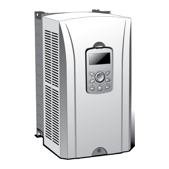
Chapter 1 Basics 1.1.5 Distribution Connect the power supply, electric motor and operating signals(control signals) to the terminal block. If you fail to connect them correctly, the inverter and peripheral devices might be damaged. 1.2 Names and Uses of Parts 1.2.1 End product (not more than 75 kW) Keypad Front cover:... -
Page 20: End Product (More Than 90Kw)
Chapter 1 Basics 1.2.3 End Product (more than 90kW) Keypad Cooling fan Volt for upper front Upper front cover cover fix (left side) Volt for upper front Volt for lower front cover fix (right side) cover fix (left side) Volt for lower front Lower front cover cover fix (right side) Power input... -
Page 21: Rated Input And Output:: Input Voltage Of 200V Class (0.75~22Kw)
Chapter 2 Specifications 2.1 Specifications 2.1.1 Rated Input and Output : Input voltage of 200V class (0.75~22kW) Type : SV xxx iS7 – 2x 0008 0015 0022 0037 0055 0075 0110 0150 0185 0220 [HP] Motor Applied [kW] 0.75 18.5 Rated Capacity 12.2 17.5... -
Page 22: Rated Input And Output : Input Voltage Of 400V Class (30~160Kw)
Chapter 2 Specifications 2.1.3 Rated Input and Output : Input voltage of 400V class (30~160kW) Type : SV xxx iS7 – 4x 0300 0370 0450 0550 0750 0900 1100 1320 1600 [HP] Motor Applied [kW] Rated Capacity [kVA] Rated Current[A] Output Frequency 0 ~ 400 [Hz] (Sensorless-1:0~300Hz, Sensorless-2,Vector:0~120Hz) Output Voltage [V]... - Page 23 Chapter 2 Specifications 2) Operation Operating Method Selectable among keypad/terminal block/communication operation Analog: 0 ~ 10[V], -10 ~ 10[V], 0 ~ 20[mA] Frequency Setting Digital: keypad PID control, up-down operation, 3-wire operation, DC break, Frequency limit, Frequency jump, Second function, Slip compensation, Reverse rotation prevention, Operating Function Auto restarting, Inverter By-pass, Auto tunning Flying Start, Energy buffering, Power breaking, Flux breaking, Leakage current reduction, MMC, Easy Start.
-
Page 24: Chapter 3 Installation
Chapter 3 Installation 3.1 Installation 3.1.1 Cautions before installation Be careful so that the plastic parts of the inverter may not be damaged. Do not move the product holding the cover only. Do not install the product where there is vibration, a press or truck. Life of the inverter greatly influenced by the surrounding temperatures, make sure that the surrounding temperature does not exceed the permitted temperature (-10 ~ 50°C). - Page 25 Chapter 3 Installation Caution Avoid direct rays of light or a warm and humid place. Install the inverter in a closed panel or clean place free from foreign substances such as oil mist and fiber dust. If you install two or more inverters inside the panel, be careful about the location of the ventilation fan and inverter. See the figure below.
-
Page 26: Exterior And Dimension (Ul Enclosed Type 1, Ip21 Type)
Chapter 3 Installation 3.1.2 Exterior and Dimension (UL Enclosed Type 1, IP21 Type) 1) SV0008-0037iS7 (200V/400V) 2) SV0055-0075iS7 (200V/400V) - Page 27 Chapter 3 Installation 3) SV0110-0150iS7 (200V/400V) 4) SV0185-0220iS7 (200V/400V)
- Page 28 Chapter 3 Installation 5) SV0300-0450iS7 (400V)
- Page 29 Chapter 3 Installation 6) SV0550-0750iS7 (400V)
- Page 30 Chapter 3 Installation 7) SV0900-1100iS7 (400V)
- Page 31 Chapter 3 Installation 8) SV1320-1600iS7 (400V)
-
Page 32: External Dimension (Ul Enclosed Type12, Ip54 Type)
Chapter 3 Installation 3.1.3 External dimension (UL Enclosed Type12, IP54 Type) 1) SV0008-0037iS7 (200V/400V) - Page 33 Chapter 3 Installation 2) SV0055-0075iS7 (200V/400V) 3-10...
- Page 34 Chapter 3 Installation 3) SV0110-0150iS7 (200V/400V) 3-11...
- Page 35 Chapter 3 Installation 4) SV0185-0220iS7 (200V/400V) 3-12...
- Page 36 Chapter 3 Installation 3.1.4 Dimension and Weight of frame (UL Enclosed Type 1, IP 21 Type) Non DCR Non EMC Non EMC&DCR Weight Inverter Capacity W[mm] H[mm] D[mm] Product Product Product [Kg] weight[Kg] weight[Kg] weight[Kg] SV0008iS7-2/4 SV0015iS7-2/4 SV0022iS7-2/4 SV0037iS7-2/4 SV0055iS7-2/4 SV0075iS7-2/4 SV0110iS7-2/4 17.2...
- Page 37 Chapter 3 Installation 3.1.5 Dimension and Weight of Frame (UL Enclosed Type 12, IP54 Type) EMC&DCR Non DCR Non EMC Non EMC&DCR Inverter Capacity W[mm] H[mm] D[mm] Weight[Kg] Weight[Kg] Weight[Kg] Weight[Kg] SV0008iS7-2/4 SV0015iS7-2/4 SV0022iS7-2/4 SV0037iS7-2/4 SV0055iS7-2/4 12.8 10.2 12.1 SV0075iS7-2/4 12.9 10.3 12.2...
-
Page 38: Installation Guide (Ul Enclosed Type12, Ip54 Type)
Chapter 3 Installation 3.1.6 Installation Guide (UL Enclosed Type12, IP54 Type) 1) How to separate IP54 keypad cover and keypad - Release the upper/lower screw on the transparent keypad cover and then separate the transparent cover from the inverter. - Separate the keypad from the inverter. 2) How to separate IP54 front cover - Loosen the captive screws (nine or thirteen, depending on the size of the frame) around the edge of the cover. - Page 39 Chapter 3 Installation 2) Mounting the inverter - Remove the four rubber packings on the corner. - Mount the inverter onto fixing hole on the panel and securely tighten the four screws or bolts. - Place the four rubber packings to the each corner. 3) Power cable wiring - Connects the input/output power cable as followed picture.
- Page 40 Chapter 3 Installation 4) How to attach the IP54 front cover - Place the front cover matching with plate hole. - Securely tighten the screw at the corner of front cover. - Connect the cable to the keypad and then place the front cover on the inverter. - Place the transparent keypad cover on the keypad and tighten the upper/lower screw.
-
Page 41: Chapter 4 Wiring
Chapter 4 Wiring 4.1 Wiring 4.1.1 How to separate front cover when wiring Remove Keypad on the product and release fixed volt of the lower end of up cover. 1) How to separate Keypad Under pressing the lower end of keypad, pull the upper part of keypad. - Page 42 Chapter 4 Wiring 3) How to separate front cover [IP21 Type] Separate front I/O board control circuit cover Terminal releasing the fixed bolt. Power circuit terminal [IP54 Type] Separate the transparent keypad cover releasing fixed bolt and then separate keypad. Separate the front cover releasing fixed bolt.
-
Page 43: How To Separate Front Cover When Wiring (90~160 Kw)
Chapter 4 Wiring 4.1.2 How to separate front cover when wiring (90~160 kW) Releasing the right/left fixed bolt on the lower front cover and get down the lower front cover and then open it. Now, you can wire power part (R/S/T, P/N, U/V/W) and signal cable (terminal block, encoder option, communication operation, PLC option etc.). -
Page 44: Built-In Emc Filter
Chapter 4 Wiring 4.1.3 Built-in EMC Filter iS7 inverter has built-in EMC Filter. It has effect in reducing air electric wave noise of inverter input part. It’s initial setting is OFF. If you are to ON, Connect please short pin on the EMC filter ON/OFF Connector. 1) How to set EMC Filter functions (Less than 7.5kW Products) - Cut off plastic cover which marked below. - Page 45 Chapter 4 Wiring 3) How to set EMC Filter functions (11~22kW Products) EMC filter ON/OFF set terminal is located in lower part of the 11~22KW Terminal as shown figure below. Initial set is OFF. When the green wire is connected in upper metal connection terminal, EMC filter is ON and EMC filter is OFF if it is connected in insulated connection terminal.
-
Page 46: Wiring Precaution
Chapter 4 Wiring 4.1.4 Wiring precaution 1) The internal circuits of the inverter will be damaged if the incoming power is connected and applied to output terminals (U, V, W). 2) Use ring terminals with insulated caps when wiring the input power and motor wiring. 3) Do not leave wire fragments inside the inverter. -
Page 47: Terminal Wiring Diagram (Power Terminal Block)
Chapter 4 Wiring 4.1.6 Terminal wiring diagram (POWER terminal block) 1) Wiring of Inverter below 7.5kW Ground terminal R(L1) S(L2) T(L3) P(+) N(-) External Fuse 3Phase 3Phase Dynamic brake resistor Motor 3-phase AC input power supply 2) Wiring of 11~22kW Product R(L1) S(L2) T(L3) -
Page 48: Terminals Of Main Circuit
Chapter 4 Wiring 4.1.7 Terminals of main circuit 1) 0.75 ~ 22 kW (200V/400V) R(L1) S(L2) T(L3) P(+) N(-) Dynamic 3 Phase AC Brake Resistor Motor Inpu Terminal Symbol Terminal Name Description R(L1),S(L2),T(L3) AC power supply input Connects normal AC input P(+) (+) AC voltage terminal (+) DC link voltage terminal... - Page 49 Chapter 4 Wiring 3) 90 ~ 160 kW (400V) R(L1) S(L2) T(L3) P(+) N(-) P N B1 B 3 Phase AC Dynamic Input brake unit Motor DBR Dynamic brake resistor Terminal Symbol Terminal Name Description R(L1),S(L2),T(L3) AC power supply input Connects normal AC input P(+) (+)DC voltage ternimal...
-
Page 50: Specifications Of Power Terminal Block And Exterior Fuse
Chapter 4 Wiring 4.1.8 Specifications of power terminal block and Exterior fuse Cable Screw Exterior fuse Terminal Inverter applied torque mm² screw size (Kgf·cm) R,S,T U,V,W R,S,T U,V,W Current Voltage 0.75 kW 7.1~12 500V 1.5 kW 7.1~12 500V 2.2 kW 7.1~12 500V 3.7 kW... -
Page 51: Control Terminal Line Diagram (Basic I/O Terminal Block)
Chapter 4 Wiring 4.1.9 Control terminal line diagram (Basic I/O terminal block) NPN (Sink) /PNP (Source) set terminal I / PTC set terminal 1) How to set NPN (Sink)/PNP (Source) iS7 serves 2 sequence input terminal of control circuit: NPN mode (Sink mode) and PNP mode(Source mode). It is possible to change the logic of input terminal with NPN mode (Sink mode) and PNP mode (Source mode) by using NPN (Sink)/PNP (Source) set terminal. - Page 52 Chapter 4 Wiring (2) PNP mode (Source mode) – When use inner source Set NPN (Sink)/PNP (Source) switch into PNP. 24 (24V inner source) is common terminal of contact point input signal. PNP mode (Source mode) – Set NPN (Sink)/PNP (Source) switch into PNP When use exterior source. If you want try to use exterior 24V source, connect exterior source (-) terminal with CM (24V GND).
- Page 53 Chapter 4 Wiring 1) Example of Distribution Relay2 Open Collector power (Normal Open) Output supply Relay1 (Normal Open) In case of analog In case of analog voltage input with current input Digital contact point input variable resistance (4~20 mA input) (NPN/PNP, Sink/Source mode support) (-10V~+10V input) Open Collector...
- Page 54 Chapter 4 Wiring 4.1.10 Control terminal line diagram (Insulated I/O terminal block) NPN (Sink)/ PNP (Source) Set terminal I / PTC Set terminal 1) Example of Distribution Open Collector Relay2 power Output (Normal Open) supply Relay1 (Normal Open) In case of analog In case of Digital contact point input voltage input with...
-
Page 55: Control Circuit Terminal
Chapter 4 Wiring 4.1.11 Control circuit terminal 1) Contact point start function selection Terminal Type Terminal Name Terminal Description Symbol Multi-function P1~P8 Available by defining as multi-function input input1~8 Common terminal of the contact point input terminal Contact Sequence (note: In case of Basic I/O, common terminal is different from the point start common terminal 5G common terminal) -
Page 56: Specifications Of Signal Terminal Block Distribution
Chapter 4 Wiring 4.1.12 Specifications of signal terminal block distribution Terminal Cable size Electric specifications Type Name P1~P8 Multi-function input terminal Contact point common terminal Common earth for multi function input (In case of Basic I/O, terminal CM is different from 5G) Analog frequency setting Output voltage : +12V 0.33... -
Page 57: Operation Checking
Chapter 4 Wiring 4.2 Operation Checking IS7 provides EASY START MODE helping with the basic parameter setting using the keypad by distribution shown above when power is first supplied. 4.2.1 Easy start Easy Start gets started when power is first supplied after you purchase the product or power is re-supplied after the set parameters are all initialized. -
Page 58: Checking For Normal Working
Chapter 4 Wiring 4.2.3 Checking for normal working 1) Motor forward/reverse direction and Normal working checking by KEYPAD operation After setting Cmd Source of DRV-06 is 0: Keypad, Freq Ref Src of DRV-07 is 0: Keypad-1 and set DRV-01 : Cmd Frequency into temporary speed, Command forward operation by pressing FWD please. -
Page 59: Chapter 5 Peripheral Devices
Chapter 5 Peripheral Devices 5.1 Peripheral Devices 5.1.1 Composition of peripheral devices It is required to connect the inverter correctly by selecting proper peripheral devices. Wrong system composition or connection might impair normal operation or cause significant life span decrease. At worst, the inverter might be damaged, so use the product properly according to the manual and cautions. -
Page 60: Specifications Of Wiring Switch, Electronic Contactor And Reactor
Chapter 5 Peripheral Devices 5.1.2 Specifications of wiring switch, Electronic contactor and Reactor 1) Specifications of Wiring switch and Electronic contactor Wiring switch Wiring switch Inverter Electronic Inverter Electronic Short circuit switch Short circuit switch capacity contactor capacity contactor (LS) (LS) 0008iS7-2 ABS33b,EBS33... - Page 61 Chapter 5 Peripheral Devices 2) AC Reactor Specifications AC Reactor Specifications AC Reactor Specifications INVERTER INVERTER 0008iS7-2 1.20 0008iS7-4 4.81 0.88 3.23 0015iS7-2 0015iS7-4 0022iS7-2 0.56 0022iS7-4 2.34 0.39 1.22 0037iS7-2 0037iS7-4 0055iS7-2 0.28 0055iS7-4 1.14 0.20 0.81 0075iS7-2 0075iS7-4 0110iS7-2 0.15 0110iS7-4...
-
Page 62: Dynamic Breaking Unit (Dbu) And Resistors
Chapter 5 Peripheral Devices 5.1.3 Dynamic breaking unit (DBU) and Resistors 1) Dynamic Breaking Unit type Dimensions Type Voltage Applied Motor 30 ~ 37 kW SV037DBH-4 Group 1. Non UL type 45 ~ 55 kW Refer to Dimensions SV075DBH-4 75 kW 30 ~ 37 kW SV370DBU-4U 45 ~ 55 kW... - Page 63 Chapter 5 Peripheral Devices 4) Dimensions - Group 1 - Group 2 2-Ø5.5 y n a m ic n it ra k in g Dynamic Braking Unit RESET POWER W IR IN G (P 2) 5) Display Functions DB Resistors connect with B1, B2 of DB Unit. DBU has 3 LEDs. Red LED which is located in middle displays supplying main power, one Green LED which is right side displays under breaking and another green LED which is left side displays Over Heat Trip(OHT).
- Page 64 Chapter 5 Peripheral Devices 6) DB Resistors (1) Option type Dynamic Breaking Unit Following table has reference that DC breaking torque: 150%, %ED: 5%. Rating Watt of DBU has to be doubled when %ED is 10%. 150% Breaking Torque, 5%ED Inverter Voltage Class Type...
-
Page 65: Chapter 6 How To Use Keypad
Chapter 6 How to Use Keypad 6.1 How to Use Keypad 6.1.1 Standard KEYPAD appearance and description (Graphic keypad) Standard Keypad is used in Inverter parameter setting, Monitor display and Inverter operations. 1) Dimensions... - Page 66 Chapter 6 How to use Keypad 2) Key Functions 14. Move to UP 1. Cancel(ESC) 13. PROGRAM set 2. Move to Left 12. Move to Right 3. MODE selection 11. Multi-Function 10. Move to down 4.Reverse operation 9. Forward operation LED 5.
- Page 67 Chapter 6 How to Use Keypad 3) Composition of Display (1) Monitor Mode Multi-function Key Operating/Frequency command Inverter Operating Status Mode Display Status Display Item MON T/K N STP 0.00Hz Monitor Mode Display Item 1 Monitor Mode Monitor Mode Display Item 2 Cursor Monitor Mode Display Item 3 (2) Parameter change display...
-
Page 68: Mode Shift
Chapter 6 How to use Keypad 4) Display Item List (1) Mode Display Items : see “Mode shift” on Page 6-8. (2) Group Display Items : see “Group shift” on page 6-10. (3) Operation Command/Frequency Command Display Items (Type of Seq and number of steps are displayed during auto sequence operation) (4) Monitor Display Items Function... - Page 69 Chapter 6 How to Use Keypad Function Display Description Operating forward Operating reversely DC output Warning Stalling Speed Search SW OC controlled HW OC controlled Auto Tuning (7) Status Display Items: see “Operating status monitoring” on Page 6-17. (8) Monitor Mode Display Items: see “Operating status monitoring” on Page 6-17.
- Page 70 Chapter 6 How to use Keypad 6.1.2 Menu composition SV-iS7 series inverter consists of the following 5 modes. Each mode has its own function items suitable for the properties and especially the parameter mode displays the functions necessary for inverter operation in groups.
- Page 71 Chapter 6 How to Use Keypad 1) Parameter mode Mode Display Description Has functions necessary for operation including Drive group frequency/acceleration/deceleration time setting and operation command selection, etc. Can set the basic functions such as the motor parameter and sequential Basic group frequency, etc.
- Page 72 Chapter 6 How to use Keypad 6.1.3 Mode shift Monitor Config Parameter Trip User&Macro 1) Mode Shift at the time of delivery You can change the display as follows if you shift modes by using the mode key. The User/Macro Mode and Trip Mode are not displayed at the time of the product being delivered.
- Page 73 Chapter 6 How to Use Keypad 2) Mode Shift with User/Macro Mode and Trip Mode If the user registers the user code or sets the macro function using the multi-function key, the User/Macro Mode will be displayed unlike the mode shift at the time of the product delivery. In addition, in case of a trip during operation, the Trip Mode will be displayed and the trip information will be saved in the trip mode as past history if you withdraw the trip using RESET function.
- Page 74 Chapter 6 How to use Keypad 6.1.4 Group shift You can make inter-group shift by using Left/Right keys after shift to Parameter Mode or User/Macro Mode using the Mode key. Protection Group Movable by MODE Key Ex) Monitor->Parameter Application Option Card Macro 2 Application Macro 1...
- Page 75 Chapter 6 How to Use Keypad STP 0.00Hz 00 Jump Code - The group changed in sequence, PRT is displayed. 40 CODE Load Duty Heavy Duty - Press Right Shift key once. Phase Loss Chk STP 0.00Hz 00 Jump Code 9 CODE - You come back to the Drive Group(DRV) of Parameter Group.
- Page 76 Chapter 6 How to use Keypad 6.1.5 Code(Function Item) shift 1) Code shift in monitor mode If you press Up and Down keys where the cursor is, names of frequency and current, etc. will be displayed. MON T/K N STP 0.00Hz - Power on, a display emerges as shown on the left.
- Page 77 Chapter 6 How to Use Keypad 2) Code shift (function Items) in other modes and groups Using Up and Down keys: The following figures give an example of shifting the code by using Up and Down keys in DRV and BAS of Parameter Mode. Code shift in other modes are the same. MON T/K N STP 0.00Hz - Power on, the display emerges as on the left.
- Page 78 Chapter 6 How to use Keypad STP 0.00Hz 00 Jump Code CODE - Enter 9 using Up key and press PROG. 1~99 CODE STP 0.00Hz 09 Control Mode 10 Torque Control - You shift to Control Mode of code number 9. ----- ----- 11 JOG Frequency...
-
Page 79: Parameter Setting
Chapter 6 How to Use Keypad 6.1.6 Parameter setting 1) Parameter setting in monitor mode You can set some parameters including frequency in Monitor Mode. The following is an example of frequency setting. MON T/K N STP 0.00Hz - Check whether the cursor is in frequency item and the 09 frequency setting method in DRV is keypad. - Page 80 Chapter 6 How to use Keypad 2) Parameter setting in other modes and groups This gives an example of changing frequency in the Drive Group of Parameter Mode. You can do so too in other modes or groups. STP 0.00Hz 00 Jump Code - This is the initial display of Parameter Mode.
- Page 81 Chapter 6 How to Use Keypad 6.1.7 Operating status monitoring 1) Using monitor mode You can monitor 3 items at a time in Monitor Mode. Some items including frequency can be edited. Displayed items can be selected by the user in Config Mode(CNF). - This is the initial display of Monitor Mode.
- Page 82 Chapter 6 How to use Keypad 2) Possible to monitoring items Function Mode Code Setting Range Initial Value Display Anytime Para Frequency 0: Frequency Monitor Line-1 Speed 0: Frequency Monitor Line-2 Output Current 2:Output Current Monitor Line-3 3:Output Voltage Output Voltage Output Power WHour Counter DCLink Voltage...
- Page 83 Chapter 6 How to Use Keypad 3) How to use status display The items displayed on the top right of the keypad are displayed in modes other than Monitor Mode as well. Thus if you register a variable you are interested in the display, you can monitor it at any time regardless of the mode shift or change.
- Page 84 Chapter 6 How to use Keypad 6.1.8 Failure status monitoring 1) Failure during operation TRP current Over Voltage (01) - In case of a failure during operation, the mode automatically shifts to 01 Output Freq Trip Mode and the type of the current failure is displayed. 48.30 Hz 02 Output Current TRP Last-1...
- Page 85 Chapter 6 How to Use Keypad 3) Saving and monitoring of failure history Previous failures are saved in Trip Mode. Up to 5 failures can be saved. Failure history is saved not only by Reset but also in case of a low voltage failure due to power off. If the number of failure exceeds 5, the failures before the latest 5 ones are automatically deleted.
-
Page 86: How To Initialize Parameter
Chapter 6 How to use Keypad 6.1.9 How to initialize parameter You can initialize the parameter that has been changed by the user to the initial state at the time of delivery. Not only the entire parameter but a group of the parameter mode can be selected and initialized. MON T/K N STP 0.0A... -
Page 87: Basic Functions
Chapter 7 Basic Functions 7.1 Basic Functions 7.1.1 How to set frequency (When you want to set frequency) Group Code No. Function Display Initial Display KeyPad-1 KeyPad-2 Freq Ref Src Int 485 Encoder Fied Bus Select the frequency setting method in code 07 of DRV Group. Digital setting by using the keypad, analog setting by using voltage (V1) and current (I1) input of the control terminal block and built-in RS485 port or communication option are available for operating frequency setting from the external controller. - Page 88 Chapter 7 Basic Functions 3) Frequency setting by voltage input (V1 terminal) of the terminal block: V1 Group Code No. Function Display Setting Displayed Unit Freq Ref Src Enter 10~+10V or 0~+10V using the voltage (V1) input terminal of the terminal block. If you enter -10~+10V, you can change the revolution direction of the motor according to the symbol of the voltage signals.
- Page 89 Chapter 7 Basic Functions IN-05 V1 Monitor: displays the voltage input into the V1 terminal. This is used for monitoring the currently input voltage. IN-07 V1 Filter: used when the set frequency value fluctuates greatly due to the environment such as noise. If you set the filter time constant high, you can reduce the frequency fluctuation but the response gets slower.
- Page 90 Chapter 7 Basic Functions Output Frequency[Hz] 60.00 59.94 0.12 0.06 Analog Input[V] 9.925 0.025 9.975 0.075 0.175 (3) If -10~+10V is input, Group Code No. Function Display Setting Displayed Setting Range Unit Freq Ref Src Freq at 100% 60.00 0.00~Max. Freq. V1 Monitor 0.00 0~10V...
- Page 91 Chapter 7 Basic Functions The output frequency of bipolar voltage input (-10~+10V) is as follows. Forward O utput Frequency -10~0[V] 0~10[V] Input Voltage Reverse O utput Frequency IN-12 V1 –volt x1’~ IN-15 V1 –Perc y2’: You can set the slope and offset value of the output frequency of (-) input voltage as follows.
- Page 92 Chapter 7 Basic Functions 4) Frequency setting by current input into terminal block (I1 Terminal) Group Code No. Function Display Setting Displayed Setting Range Unit Freq Ref Src Freq at 100% 60.00 0.00~ Max Freq I1 Monitor 0.00 0~20 I1 Filter 0~10000 msec I1 Curr x1...
- Page 93 Chapter 7 Basic Functions 5) Frequency command by advanced I/O option card You can input the frequency command by using -10~+10V (V2 terminal) and 0~20mA (I2terminal) if you mount an extended I/O card on the inverter option slot. ▶ -10~+10V Input Group Code No.
- Page 94 Chapter 7 Basic Functions 6) Frequency setting by Encoder Option Card (If you want use pulse input to frequency command) Group Code No. Function Display Setting Displayed Setting Frequency Unit Freq Ref Src Encoder 0.00~Max. Freq. Freq at 100% 60.00 Enc Opt Mode Reference Enc Type Sel...
-
Page 95: Analog Command Frequency Fixation
Chapter 7 Basic Functions If you set DRV-07 Freq Ref Src at Int 485, you can control the inverter through communication with the higher controller (PLC or PC) by using the RS485 (+S, -S) terminal of the terminal block. For details, see Communication Functions, Chapter 11. - Page 96 Chapter 7 Basic Functions 7.1.4 Sequential frequency setting Group Code No. Function Display Setting Displayed Setting Range Unit Freq Ref Src 50~64 Step Freq - x Speed-L Speed-M 65~75 Px Define Speed-H 10 Speed-X InCheck Time msec *Step Freq – x : Step Freq -1~15, Px: P1~P8, P9~P11 (Option) Sequential operation is available by using the multi-function terminal.
- Page 97 Chapter 7 Basic Functions [Example of speed-8] If multi-function terminals P5, P6, P7 and P8 are set at Speed-L, Speed-M, Speed-H and Speed-X respectively, you can operate it as follows. Speed FX or RX IN-89 In Check Time: If you use the multi-function terminal for sequential frequency setting, you can set the in check time for the terminal block input within the inverter.
- Page 98 Chapter 7 Basic Functions 2) Terminal Block operating command 1 : Fx/Rx-1 Group Code No. Function Display Setting Display Setting Range Unit Cmd Source Fx/Rx-1 65~75 Px Define 65~75 Px Define Run On Delay 1.00 0.00~100 *Px : P1~P8, P9~P11 (option) Set DRV Group 06 at Fx/Rx-1.
- Page 99 Chapter 7 Basic Functions 4) Operating Command by RS-485 Communication: Int 485 Group Code No. Function Display Setting Display Setting Range Unit Cmd Source Int 485 Int485 St ID 0~250 Int485 Proto ModBus RTU Int485 BaudR 9600 1200~38400 Int485 Mode D8 / PN / S1 You can control the inverter through communication with a higher controller (PLC or PC) by using terminal RS485 (+S, -S) on the terminal block if you set DRV-06 Cmd Src at Int 485.
-
Page 100: Prevention Of Forward Or Reverse Rotation: Run
Chapter 7 Basic Functions 4) Shift from Remote to Local In case of Shift from Remote to Local, the signal representing the command source and frequency source at the top of MON Mode turns to K/K. The inverter stops if it has been operating in Remote status. 5) Shift from Local to Remote In case of shift from Local to Remote, K/K at the top of MON Mode is represented by a different signal in conformity to the previously set command source and frequency source. - Page 101 Chapter 7 Basic Functions 7.1.8 Run immediately with power On: Power-on Run Group Code No. Function Display Setting Display Setting Range Unit Cmd Source 1 ~ 2 Power-on Run --- yes --- No/Yes With power supplied to the inverter and the terminal block operating command being ON, the inverter starts operating. This is effective only when the DRV Group 06 command source is set at 1 (Fx/Rx-1) or 2 (Fx/Rx-2).
- Page 102 Chapter 7 Basic Functions Frequency Reset Operating Command When PRT-08=1 When PRT-08=0 Caution When using this function, if you reset the inverter in the terminal block of loader after a trip, the motor starts rotating. Be careful of an accident. 7.1.10 Setting of accelerating/decelerating time and pattern 1) Setting of accelerating/decelerating time on the basis of the maximum frequency Group...
- Page 103 Chapter 7 Basic Functions Caution 90 ~ 160 kW product’s acceleration initial value is 60.0sec and deceleration initial value is 90.0sec. Please do not confuse that displayed value at left bottom of keypad is D : 20.0, D : 30.0 it is applied for below 75kW product.
- Page 104 Chapter 7 Basic Functions 3) Setting of Acc/Dec Time Using Multi-Function Terminal Group Code No. Function Display Setting Display Setting Range Unit Below 75 kW 20.0 Acc Time 0~600 Above 90 kW 60.0 Below 75 kW 30.0 Dec Time 0~600 Above 90 kW 90.0 70~74...
- Page 105 Chapter 7 Basic Functions You can change the Acc/Dec slope without using the multi-function terminal. The inverter operates at the slope set at BAS-70, 71 below the Acc/Dec switching frequency set at ADV-60 of the operating frequency. However, if the operating frequency rises over the Acc/Dec switching frequency, the inverter runs at the Acc/Dec slope set at DRV-03 and 04.
- Page 106 Chapter 7 Basic Functions Linear S-Curve Frequency Operating Command Acc Time Dec Time ADV-03 Acc S Start: You can adjust the slope of the curve when you set the Acc/Dec pattern as S-curve. This is used to adjust the curvilinear ratio of S-curve when acceleration begins. The curve ratio sets the ratio of the curve acceleration of the 1/2 frequency on the basis of a half of the target frequency.
- Page 107 Chapter 7 Basic Functions 7.1.12 Acc/Dec Stop command Group Code No. Function Display Setting Display Unit 65~75 Px Define 25 XCEL Stop You can stop acceleration or deceleration using the multi-function terminal and operate at steady speed. The following figure illustrates use of multi-function terminal P8. Frequency Operating Command...
- Page 108 Chapter 7 Basic Functions Base Frequency Start Frequency Frequency Inverter Rated Frequency Voltage Operating Command 2) Double reduction V/F pattern operation (Using fan, pump load) Group Code No. Function Display Initial Setting Display Unit Square 1 V/F Pattern Square 2 This is an operation pattern of which the starting characteristic such as the fan and pump is suitable for the load of double reduction type.
-
Page 109: Torque Boost
Chapter 7 Basic Functions The user can set the pattern suitable for the V/F pattern and load characteristics of a special motor rather than a ordinary induction motor. BAS-41 User Freq 1 ~ BAS-48 User Volt 4: Select a frequency between the start frequency and maximum frequency, set the user frequency(User Freq x) and set the voltage corresponding to each frequency at the user voltage(User Volt x). - Page 110 Chapter 7 Basic Functions Voltage 100 % No Torque Boost Forward Torque Boost time Reverse Torque Boost 2) Automatic Torque Boost (Choosing automatic selection function for greater starting torque) Group Code No. Function Display Setting Display Unit Torque Boost Auto Auto Tuning Rs+Lsigma The inverter automatically calculates the torque boost and produces voltage by using the motor parameter.
- Page 111 Chapter 7 Basic Functions 7.1.16 Selection of starting method (When you want to change starting method) If an operating command is input in the static state, you can select the inverter starting method. Group Code No. Function Display Setting Display Initial Setting Display Unit Accel...
- Page 112 Chapter 7 Basic Functions 7.1.17 Stop method selection (Changing stop method) You can choose the method of stopping the motor when the inverter is given a stop command during operation. 1) Decelerating Stop Group Code No. Function Display Setting Display Unit Stop Mode This is a normal decelerating method.
- Page 113 Chapter 7 Basic Functions ADV-14 ADV-15 Caution ADV-17 Frequency When D.C. Braking is big or control time is too long, overheating and malfunction may occur. Voltage Caution Current ADV-16 Since D.C Braking is a standard of rating current for pre-set Operating motor, please do not set over value of current of inverter’s Command...
- Page 114 Chapter 7 Basic Functions 4) Power Braking (Optimum deceleration without Over-Voltage Trip) Group Code No. Function Display Setting Display Unit Stop Mode Power Braking If the inverter D.C. voltage rises above a certain level due to the regenerative energy of the motor, the decelerating slope is adjusted or re-acceleration occurs in order to reduce the regenerative energy.
- Page 115 Chapter 7 Basic Functions (1) ADV-24 Freq Limit: If you set the frequency as Yes with the initially set value being No, you can set the frequency only between the upper limit(ADV-25) and lower limit(ADV-26). With frequency set as No, ADV-25 and ADV-26 codes are not displayed.
- Page 116 Chapter 7 Basic Functions Frequency ADV-33 ADV-32 ADV-31 ADV-30 ADV-29 ADV-28 (Voltage Input) I (Current Input) 20mA Operating Command Frequency Declining Frequency Rising 7.1.20 Selection of second operating method (By-pass operation) You can enter the frequency, operating command and torque reference as the second set values by using the multi- function input terminal.
- Page 117 Chapter 7 Basic Functions 7.1.21 Multi-function input terminal control (Improving responsiveness of input terminal) You can set the filter time constant and contact point type for the multi-function input terminal of the inverter terminal Group Code No. Function Display Setting Display Setting Range Unit DI On Delay...
- Page 118 Chapter 8 Applied Functions 8.1 Applied Functions 8.1.1 Override frequency setting using auxiliary frequency command (Setting frequency of various computation conditions using main and auxiliary speed such as Draw operation) Group Code No. Function Display Setting Display Setting Range Unit Freq Ref Src Keypad-1 AUX Ref Src...
- Page 119 Chapter 8 Applied Functions Final Command Frequency Computation Setting Type Expression main speed command value / (BAS03 x 2 x (BAS01 – 50)) M/(G*2*(A-50)) M[HZ]/(G[%]*2*(A[%]-50[%])) main speed command value + main speed command value x BAS03 M[HZ]+M[HZ]*G[%]*2*(A[%]- 7 M+M*G*2*(A-50) x 2 x (BAS01 – 50) 40[%]) Caution If the maximum frequency is high, there might be an error of output frequency due to analog input and...
- Page 120 Chapter 8 Applied Functions If 6V is being input into V1, the frequency corresponding to 10V is 60Hz, so the auxiliary speed A in the table below is 36Hz(= 60[Hz]x(6[V]/10[V])) or 60%(=100[%]X(6[V]/10[V]) according to the condition. Setting Type Final Command Frequency M[Hz]+(G[%]*A[Hz]) 30Hz(M)+(50%(G)x36Hz(A))=48Hz M[Hz]*(G[%]*A[%])
- Page 121 Chapter 8 Applied Functions If 10.4mA is being input into I1, the frequency corresponding to 20mA is 60Hz, so the auxiliary speed A in the table below is 24Hz(=60[Hz]x((10.4[mA]-4[mA])/(20[mA]-4[mA])) or 40%(=100[%]x((10.4[mA]-4[mA])/(20 [mA]-4[mA])). Setting Type Final Command Frequency M[Hz]+(G[%]*A[Hz]) 30Hz(M) + (50%(G) x 24Hz(A)) = 42Hz M[Hz]*(G[%]*A[%]) 30Hz(M)x(50%(G)x40%(A))=6Hz M[Hz]/(G[%]*A[%])
- Page 122 Chapter 8 Applied Functions 2) Jog Operation by Terminal Block 2 Group Code No. Function Display Setting Display Setting Range Unit JOG Frequency 10.00 0.5~maximum frequency JOG Acc Time 20.00 0~600 JOG Dec Time 30.00 0~600 65~75 Px Define FWD JOG 65~75 Px Define REV JOG...
- Page 123 Chapter 8 Applied Functions DRV-12 (Acc time) When setting DRV-13 (Dec time) multi-key jog DRV-11 DRV-11 (Jog frequency) REV key FWD key 8.1.3 Up-Down operation Group Code No. Function Display Setting Display Setting Range Unit U/D Save Mode 65~75 Px Define 0~48 65~75 Px Define...
- Page 124 Chapter 8 Applied Functions Memorized frequency Output frequency P6(CLEAR) P7 (UP) Operation command(FX) 8.1.4 3-Wire operation (if you want operation using Push button) Group Code No. Function Display Setting Display Setting Range Unit Cmd Source Fx/Rx - x 65~75 Px Define 3-Wire 0~48 *Px : P1~P8, P9~P11 (Option)
- Page 125 Chapter 8 Applied Functions 8.1.5 Safe operation mode (if you want to limit operation through Terminal Input) Group Code No. Function Display Setting Display Setting Range Unit Run En Mode DI Dependent Run Dis Stop Free-Run Q-Stop Time 0~600 65~75 Px Define Run Enable 0~48...
- Page 126 Chapter 8 Applied Functions 8.1.6 Dwell operation Group Code No. Function Display Initial Value Setting Range Unit Starting frequency ~ Acc Dwell Freq 5.00 Maximum frequency Acc Dwell Time 0~10 Starting frequency ~ Dec Dwell Freq 5.00 Maximum frequency Dec Dwell Time 0~10 If the operating command is input, the inverter operates at steady speed for the acceleration dwell time at the set acceleration dwell frequency and resumes acceleration.
- Page 127 Chapter 8 Applied Functions * Acceleration Dwell Acc Dwell command is effective only first command input so it is not available in case the frequency passes by Acc Dwell frequency during re-acceleration on stop. Frequency Target Freq. change Acc. Dwell Acc.
- Page 128 Chapter 8 Applied Functions 8.1.7 Slip compensation operation For an induction motor, the difference between the rotation speed of the motor and the set frequency varies according to the load ratio. The slip compensation operation is used for the load that should compensation the speed difference(slip). If the control mode is sensorless or vector or V/F PG, the speed difference is automatically compensation.
- Page 129 Chapter 8 Applied Functions 8.1.8 PID control 1) PID Basic Operation This is a method commonly used among the ones of auto control. PID means P: Proportional, I: Integral, and D: Differential. By combining these 3, better control is available. Group Code No.
- Page 130 Chapter 8 Applied Functions The output frequency of the inverter goes through PID control in order to control the system process including the flow, temperature and tension and so on. APP-01 App Mode(application mode) : You can set the process PID functions by setting at No. 2 Proc PID(Process PID).
- Page 131 Chapter 8 Applied Functions For example, if APP-20 Ref Source is selected as No. 1 V1 terminal, the inputs other than V1 should be selected in APP- 21 PID F/B Source. Set as No. 18 PID Fdb Value of CNF-06~08, the feedback can be monitored. APP-22 PID P-Gain, APP-26 P Gain Scale : Sets the output ratio of the difference(error) between the reference and feedback.
- Page 132 Chapter 8 Applied Functions 2) PID Control Block Diagram Notice - If PID change operation (changes from PID operation to normal operation) comes into multi-function inputs (P1~P11), the value of [%] is converted to the one of [Hz] and is output. - Polarity of normal PID output PID OUT is unipolar and is limited by APP-29 (PID Limit Hi) and APP-30 (PID Limit Lo).
- Page 133 Chapter 8 Applied Functions 4) PID Sleep Mode(Sleep) APP-37 PID Sleep DT, APP-38 PID Sleep Freq : If the inverter continues to operate for the time set in APP-37 PID Sleep DT under the frequency set in APP-38 Sleep Freq, is stops operating and goes into Sleep Mode. For the threshold of shift from PID Sleep Mode to PID operation mode back, see APP-39 PID WakeUp Lev.
- Page 134 Chapter 8 Applied Functions 8.1.9 Auto tuning The motor parameter can be automatically measured. In addition, if the encoder option card is connected to the main body of the inverter, you can test the operation of the encoder. The motor parameters measured through auto tuning are used for auto torque boost, sensorless vector control and vector control and so on.
- Page 135 Chapter 8 Applied Functions Input Motor Rating No load Rating slip Stator Leakage voltage capacity current current frequency resistance inductance [kW] [Hz] [Ω] [mH] 53.6 15.5 1.00 0.084 1.118 18.5 65.6 19.0 1.00 0.068 0.819 76.8 21.5 1.00 0.056 0.948 104.6 29.3 1.00...
- Page 136 Chapter 8 Applied Functions 2 : ALL (Stdstl) Motor parameter is measured when motor is stopped. Measure stator resistance(Rs), leak inductance(Lsigma), and the rotor time constant(Tr) all together at the same time. This mode is available when Control Mode(DRV-09) is Sensorless-2. 3 : Rs+Lsigma The parameter is measured with the motor not operating.
- Page 137 Chapter 8 Applied Functions APO-05 Enc Pulse Sel : Sets the encoder output pulse direction. Forward operation in case of No. 0 (A+B) and reverse operation in case of No. 2 –(A+B) are selected. No. 1 is selected for use as the frequency setting reference. APO-06 Enc Pulse Num : Inputs the output pulse number per rotation.
- Page 138 Chapter 8 Applied Functions CON-45 PG P-Gain, CON-46 PG I-Gain : Sets the proportional gain of the speed controller(PG P-Gain) and integral gain(PG I-Gain). The higher the proportional gain is set, the faster the responsive characteristic is, but if it is set too high, the speed controller might be instable.
- Page 139 Chapter 8 Applied Functions BAS-15 Rated Volt(rated voltage) BAS-16 Efficiency(efficiency) Auto tuning with motor static : If the load connected to the motor axis is hard to remove, set the auto tuning item(BAS- 20 Auto Tuning) at No. 2 Rs+Lsigma for the motor parameter to be measured with the motor static. For the no-load current of the motor, the default value is used.
- Page 140 Chapter 8 Applied Functions 8.1.12 Sensorless(II) vector control Group Code No. Function Display Setting Display Unit Control Mode Sensorless-2 Torque Control Motor Capacity Changeable according to capacity of the motor Pole Number Changeable according to capacity of the motor Rated Slip Changeable according to capacity of the motor Rated Curr Changeable according to capacity of the motor...
- Page 141 Chapter 8 Applied Functions Before auto tuning, enter the items on the motor plate first. DRV-14 Motor Capacity(motor capacity) BAS-11 Pole Number(number of poles) BAS-12 Rated Slip(rated slip) BAS-13 Rated Curr(rated current) BAS-15 Rated Volt(rated voltage) BAS-16 Efficiency(efficiency) Separate the load connected to the motor shaft and set the auto tuning item at No. 1 All. The motor measures the parameter while rotating.
- Page 142 Chapter 8 Applied Functions the lower the responsiveness is. For example, if CON-23 ASR-SL I Gain1 is 100msec and CON-23 ASR-SL I Gain2 is 50.0%, the speed controller I gain at higher than the actual medium speed is 200msec. The controller gain is set according to the default motor parameter and Acc/Dec time.
- Page 143 Chapter 8 Applied Functions lower Output Voltage. In this case, set the CON-34 (SL2 OVM Perc) to 140~150% and you can operate Tripless operation in case heavy load is applied. CON-48 ACR P-Gain, CON-49 ACR I Gain : Adjusts the P gain and I gain of the current PI controller. DRV-10 Torque Control : The speed control mode and torque control mode are selected from the sensorless(II) vector control mode and used.
- Page 144 Chapter 8 Applied Functions 8.1.13 Vector control The motor operates at the vector control mode in which high precision control of speed and torque is provided with the encoder option card mounted on the main body of the inverter. Group Code No.
- Page 145 Chapter 8 Applied Functions 1) Preparation before Starting Separate the load connected to the motor axis. Motor parameter input : enter the following values shown on the motor plate. DRV-14 Motor Capacity(motor capacity) BAS-11 Pole Number(number of poles) BAS-12 Rated Slip(rated slip) BAS-13 Rated Curr(rated current) BAS-15 Rated Volt(rated voltage) BAS-16 Efficiency(efficiency)
- Page 146 Chapter 8 Applied Functions BAS-20 Auto Tuning: forward operation is run upto 20Hz if setting Enc Test of NO.3 after setting related parts of encoder explained above. After forward operation and deceleration, acceleration is run upto 20Hz. If encoder does not have any problems, auto tuning part changes to None.
- Page 147 Chapter 8 Applied Functions CON-48 ACR P-Gain, CON-49 ACR I Gain : Used in sensorless speed/torque and vector speed/torque modes and adjusts the P gain and I gain of the current PI controller. IN-65~75 Px Define 36 : ASR Gain2 If the set terminal is input, the gain can be changed after the change time(CON-19).
- Page 148 Chapter 8 Applied Functions IN-65~75 Px Define : Although the multi-function input is set at 48 Trq Bias, if the multi-function input is not ON, the Torque Bias values being input into the keypad, analog or communication are ignored. CON-60 Trq BiasFF : This is added to the torque bias to compensate for the loss from the motor rotation direction. If a (-) value is input, the torque bias decreases by the amount of the input.
- Page 149 Chapter 8 Applied Functions Group Code No. Function Display Setting Display Unit Speed Lmt Gain 65~75 Px Define Speed/Torque 31~33 Relay x or Q1 Torque Dect TD Level TD Band Caution For operation in the torque control mode, the sensorless vector mode and the basic operation conditions described in the vector control mode should be set in advance.
- Page 150 Chapter 8 Applied Functions CON-62 Speed Lmt Src : Selects the type of speed limit setting. 0 : Keypad-1, 1 : keypad-2 The speed limit is set by using the keypad. The forward speed limit is set in CON-41 FWD Speed Lmt and the reverse speed limit is set in CON-42 REV Speed Lmt.
-
Page 151: Kinetic Energy Buffering
Chapter 8 Applied Functions If the multi-function input, which is set as Speed/Torque, is ON during Vector Torque (DRV09:Vector, DRV10:Yes) operation, the operation shifts to the vector speed mode according to the Acc/Dec time set in CON50, 51. If the multi-function input, which is set as Speed/Torque, is ON during Vector Speed (DRV09:Vector, DRV10:No) operation, the operation immediately shifts to the vector torque mode. -
Page 152: Energy Saving Operation
Chapter 8 Applied Functions 8.1.18 Energy saving operation Manual Energy Saving Operation Group Code No. Function Display Setting Display Unit E-Save Mode Manual Energy Save If the inverter output current is lower than the current set in BAS-14 Noload curr (no-load current of the motor), the output voltage is reduced by the amount set at ADV-51.The standard value is the voltage before the energy saving operation starts. - Page 153 Chapter 8 Applied Functions 8.1.19 Speed search operation This is used to prevent a failure that might occur when the inverter outputs voltage during the motor idling with the output voltage of the inverter blocked. It is not accurate speed detection since the rotation speed of the motor is easily judged on the basis of output current of the inverter.
- Page 154 Chapter 8 Applied Functions Caution For correct operation, please set speed search when accelerating in case of operation from the load to sensorless II mode. It may cause over current trip or over load trip 2) Reset Starting after a Trip If bit 2 is set at 1 and PRT-08 RST Restart is set as Yes, acceleration is carried out to the frequency before the trip in speed search motion when the reset key(or terminal block reset) is input.
-
Page 155: Automatic Restart
Chapter 8 Applied Functions ADV-61 SS Sup-Current : Controls the current during speed search motion on the basis of the motor rated current. The gain of the controller is set at ADV-62 and 63. ADV-64 SS Block Time : Blocks output for the set period of time and then starts operation before starting speed search. Speed search operation is mostly used for loads with high inertia. - Page 156 Chapter 8 Applied Functions The following figure illustrates setting the number of automatic restarts at 2. Trip Steady speed operation Frequency voltage Speed search operation reset Operating command The number of auto-restart 8.1.21 Operation sound selection Setting Group Code No. Function Display Setting Display Unit...
- Page 157 Chapter 8 Applied Functions The carrier frequency according to the inverter capacity is as follows. 0.75~22kW 30~45 kW 55~75kW 90~110 kW 132~160kW 5kHz(Max 15KHz) 5kHz(Max 10KHz) 5kHz(Max 7KHz) 3kHz(Max 6KHz) 3kHz(Max 5KHz) Caution Carrier frequency default value of 90~160 kW is 3kHz. Please do not confuse with the value D: 5.0 which is displayed on the lower left part of the keypad as followed picture that the value is the default value from the below 75kW product.
- Page 158 Chapter 8 Applied Functions 8.1.22 2 Motor operation (when you want to do change operation of 2 monitors with one inverter) During change operation, connecting different 2 monitors with one inverter, 2 operation is available when the terminal defined as the 2 function is 1 for the parameter of 2 monitor.
- Page 159 Chapter 8 Applied Functions Code No. Function Display Description M2-Stall Lev Stall level M2-ETH 1min 1 minute electronic thermal incessant rated level M2-ETH Cont Electronic thermal operation level M2-LoadSpdGain Gain adjustment for load speed display M2-LoadSpdScal Scale adjustment for load speed display M2-LoadSpdUnit Unit adjustment for load speed display Example: set as follows if you want to change to 3.7kW in previous 7.5kW motor by using P3 terminal with the...
-
Page 160: Cooling Fan Control
Chapter 8 Applied Functions OUT-30 Realy 1 ~ OUT-32 MO1 Define : Sets the multi-function relay or multi-function output at No. 16 Inverter Line and No. 17 Comm Line. For relay motion sequence, see the figure below. Speed frequency interval Output frequency Operation... - Page 161 Chapter 8 Applied Functions 8.1.25 Input power frequency selection Group Code No. Function Display Initial Setting Display Unit 60/50 Hz Sel Select the inverter input power frequency. If changed from 60Hz to 50Hz, the items related to the frequency(or rpm) set higher than 60Hz are all changed into 50Hz.
-
Page 162: Parameter Initialization
Chapter 8 Applied Functions 8.1.28 Parameter initialization Group Code No. Function Display Initial Setting Display Unit Parameter Init The parameter changed by the user can be initialized to the default value set at the time of delivery. This function can initialize the data of all groups or selected groups. Initialization is not available in case of a trip or during inverter operation. - Page 163 Chapter 8 Applied Functions Caution If the parameter group view lock function is active, you cannot change functions related to inverter operation. Be sure to memorize the registered password. 2) Parameter Key Lock Group Code No. Function Display Setting Display Unit Key Lock Set Unlocked...
- Page 164 Chapter 8 Applied Functions 8.1.30 Addition to User Group (USR Grp) Group Code No. Function Display Initial Setting Display Unit Multi-Key Sel UserGrp SelKey UserGrp AllDel You can group data you have chosen from each group of the parameter group and change them. You can register up to 64 parameters in the user group.
- Page 165 Chapter 8 Applied Functions 2) How to Delete Individual Parameters Registered in User Group (USR Grp) Procedure Description If you select 4.UserGrp SelKey with the Multi-Key in CNF Mode Code will be seen at the top of the display. Move the cursor to the code you want to delete in U&M Mode USR Group.
- Page 166 Chapter 8 Applied Functions How to Launch Easy Start Procedure Description Set CNF-61 Easy Start On as Yes. Select All in CNF-40 Parameter Init and initialize all the parameters of the inverter. When the power of the inverter is first Off/On, Easy Start gets started. Through the following displays on the digital loader, set proper values.
- Page 167 Chapter 8 Applied Functions CNF-42 Changed Para: When setting as View Changed, changed parameter comparing to default value is displayed. CNF-44 Erase All Tip : deletes all the saved failure history. CNF-60 Add Title Del : this is a function to set to enable added codes in previous version to display and operate added functions when SW of inverter main body is updated with new coded.
- Page 168 Chapter 8 Applied Functions 8.1.35 Auto sequence operation Group Code No. Function Display Initial Setting Display Unit App Mode Auto Sequenc 65~75 Px Define SEQ-1 65~75 Px Define SEQ-2 65~75 Px Define Manual 65~75 Px Define Go Step 65~75 Px Define Hold Step 31~32 Relay 1, 2...
- Page 169 Chapter 8 Applied Functions AUT-01 Auto Mode : selects the type of auto sequence operation. 0 : Auto-A This is the operating method of proceeding with the automatically set steps if the terminal set at SEQ-L or SEQ-M is input among the multi-function terminal function items. 1 : Auto-B You can proceed with steps every time when a terminal set as Go-Step is input and the terminal set at SEQ-L or SEQ-M is input.
- Page 170 Chapter 8 Applied Functions 8.1.36 Traverse operation Group Code No. Function Display Initial Setting Display Unit App Mode Traverse Trv Amplit % Trv Scramb % Trv Acc Time Trv Dec Time Trv Offset Hi Trv Offset Lo 65~75 Px Define Trv Offset Lo 65~75 Px Define...
- Page 171 Chapter 8 Applied Functions 8.1.37 Brake control Group Code No. Function Display Setting Display Setting Range Unit Control Mode BR Rls Curr 50.0 0~180% BR Rls Dly 1.00 0~10.0 BR Rls Fwd Fr 1.00 0~Maximum frequency BR Rls Rev Fr 1.00 0~Maximum frequency BR Eng Dly...
- Page 172 Chapter 8 Applied Functions ADV-44, 45 ADV-47 Output frequency ADV-41 Output currency ADV-15 ADV-42 ADV-46 Motor speed Brake Output terminal Operation command Brake open interval Brake closed Brake closed interval interval When Control Mode Is Not Set at Vector Output frequency CON-10 Output...
- Page 173 Chapter 8 Applied Functions 8.1.38 Multi-function output On/Off control Group Code No. Function Display Setting Display Setting Range Unit OnOff Ctrl Src On-C Level 90.00 10~100% 0~Output contact on Off-C Level 10.00 level 31~33 Relay x or Q1 On/Off Control If the analog input value is over the set value, the output relay or multi-function output terminal can be turned ON or OFF.
- Page 174 Chapter 8 Applied Functions Group Code No. Function Display Setting Display Setting Range Unit Num of Aux No/Yes Regul Bypass None/Aux/Main Auto Ch Mode 0~99:00 Auto Ch Time 72:00 No/Yes Interlock 0.1~360.0 Interlock DT 0~100% Actual Pr Diff 0.0~600.0 Aux Acc Time 0.0~600.0 Aux Dec Time 31~33...
- Page 175 Chapter 8 Applied Functions APO-41 Aux Acc Time, APO-42 Aux Dec Time : The main motor stops PID control and normal acceleration and deceleration operation when the auxiliary motor runs or stops. When the auxiliary motor runs, the main motor decelerates to the decelerating frequency of the auxiliary motor for the decelerating time set at APO-42.
- Page 176 Chapter 8 Applied Functions 1 : Aux The motion sequence of the auxiliary motor starts with the auxiliary motor selected in APO-21(starting auxiliary motor selection). When the cumulative operating time of a main and auxiliary motor exceeds the auto change time(APO-36), the auto change condition is met.
- Page 177 Chapter 8 Applied Functions 3 phase input R S T Inverter U V W 3) Interlock This is the function of stopping the motor operating and replacing it with another motor in case of a failure of the motor. If the failure signal is input into the input terminal and the functions of the relevant terminals are set as Interlock 1~4, it will be decided whether to operate the motor according to the terminal input status.
- Page 178 Chapter 8 Applied Functions 2) If there are four motors in total and the auto change mode selection(APO-35) is set at 2(Main), the operation is as follows. If the starting auxiliary motor selection APO-21 is set at 1, motor 1 is operated by the inverter and the remaining 2, 3 and 4 are operated by the auxiliary motors and interlock signals are input to the auxiliary motors, the operation sequence is the same as the procedure described in 1) above.
- Page 179 Chapter 8 Applied Functions ADV-75 RegenAvd Level (set regeneration evasion level for press): Set DB operation evasion voltage when DC Link voltage goes up by regeneration voltage. ADV-76 CompFreq Limit (limit regeneration evasion compensation frequency for press): Set changeable frequency range for real command frequency during regeneration operation region. ADV-77 RegenAvd Pgain (P gain set for regeneration evasion compensation control machine function for press) ADV-78 RegenAvd Igain (I gain set for regeneration evasion compensation control machine function for press): Set P, I Gain of DC Link voltage limit PI control machine for regeneration operation region.
-
Page 180: Monitor Functions
Chapter 9 Monitor Functions 9.1 Monitor Functions 9.1.1 Monitor in operation - Keypad You can monitor the operating status using the keypad of the inverter. You can select the desired items to monitor in the config mode(CNF), watch three items at a time in the monitor mode and select an item in the status display. 1) Selection of Monitor Mode Display Function Mode... - Page 181 Chapter 9 Monitor Functions Setting Function terminal of the inverter terminal block. Displays the current above in percentage. If the input I1 Monitor[%] current is 0~20[mA], it is represented by 0~100%. Displays the voltage input of the V2 terminal of the I/O V2 Monitor[V] option card when you use the extended I/O option.
- Page 182 Chapter 9 Monitor Functions * WHour Counter: Describes for No.5 WHour Counter (electricity consumed by inverter) among the aforementioned Monitor items. Electricity consumption is calculated with voltage and current, and it is accumulated the calculated electricity every 1 second. The way of Electricity consumption display is followed description. 1.
- Page 183 Chapter 9 Monitor Functions * Warning If you change the default value of Hz/Rpm Sel from Hz to Rpm display, all parameters will be changed to Rpm but it is not changed automatically in monitor mode. E.g) At CNF-21 Monitor Line-1 to Frequency (Fault value), if you change the value from Hz to Rpm Display at DRV- 21 Hz/Rpm Sel, Monitor Line-1 set value is not changed.
- Page 184 Chapter 9 Monitor Functions 9.1.2 Failure status monitor – Keypad The Trip Mode displays the present failure status in case of a trip during operation. The type, operating frequency and current of the present trip can be monitored and last 5 trips can be saved. 1) Present Failure Status Monitor If a failure occurs, the present failure type is displayed as follows in the keypad display.
- Page 185 Chapter 9 Monitor Functions 2) Failure History Monitor Types of up to five previous failures can be saved and monitored. The lower the number of Last X is, the more recent failure it represents. If more than 5 failures have occurred, those that occurred before the last 5 ones are automatically deleted.
- Page 186 Chapter 9 Monitor Functions 9.1.3 Analog output 1) 0 ~ 10V Voltage Output Code Function Group Initial Setting Unit Display AO1 Mode Frequency AO1 Gain 100.0 AO1 Bias AO1 Filter msec AO1 Const % AO1 Monitor The items to be output from AO1 (Analog Output 1) terminal of the inverter terminal block are selected and their size is adjusted.
- Page 187 Chapter 9 Monitor Functions Setting Function Displays the information on the speed of the input into the Speed encoder option card. It produces 10V at maximum frequency(DRV-20) Outputs the difference between the speed reference(command) and the motor’s rotation speed that Speed inputs into the encoder option card.
- Page 188 Chapter 9 Monitor Functions 3) -10 ~ +10V Voltage Output of Extended I/O Option Card If the extended I/O option card is mounted on the option slot of the inverter, the operating status can be monitored using the bipolar voltage output of the extended I/O. Its output has a resolving power of 11bit. Code Initial Group...
-
Page 189: Selection Of Relay Function And Multi-Function
Chapter 9 Monitor Functions 9.1.4 Selection of relay function and multi-function output terminal of terminal block Function Group Code No. Initial Setting Unit Display Trip Out Mode Relay 1 Trip Mode Relay 2 Q1 Define FDT-1 34~36 Q2~Q4 Define DO Status According to OUT-30 Failure output, Failure Relay will operate Bit on status (ON) : Bit off status (OFF) :... - Page 190 Chapter 9 Monitor Functions The detected frequency width is set as follows and the illustration below shows the frequency width having been set at 10Hz. Code Function Group Initial Setting Unit Display FDT Band (Hz) 10.00 40Hz 20Hz Frequency 40Hz 35Hz 20Hz 15Hz...
- Page 191 Chapter 9 Monitor Functions Group Code No. Function Display Initial Setting Unit FDT Frequency 30.00 FDT Band (Hz) 10.00 35Hz 30Hz 25Hz Frequency Operating command 4 : FDT-4 Can operate setting the conditions of acceleration and deceleration at the same time. Acceleration : operating frequency >= detected frequency Deceleration : operating frequency >...
- Page 192 Chapter 9 Monitor Functions 10 : Over Voltage (over voltage failure) Active if the inverter DC power voltage goes up above the protective action voltage. 11 : Low Voltage (low voltage failure) Active if the inverter DC power voltage goes down below the low voltage protective action level. 12 : Over Heat (inverter cooling fan overheat) Active if the inverter cooling fan is overheated.
- Page 193 Chapter 9 Monitor Functions Function 8.1.19 Speed search operation. 20 : Step Pulse, 21 : Seq Pulse (auto sequence operation) Active after the advance step of the auto sequence operation and a cycle of the operating sequence. 22 : Ready (stand by for operating command) Active when the inverter is normally operating and ready to operate waiting for operating command from outside.
- Page 194 Chapter 9 Monitor Functions 27 : Torque Dect Active if the torque, with the control mode set as sensorless or vector, is below the following levels. Code Function Group Initial Setting Unit Display Sensorless-1, Control Mode Sensorless-2, Vector TD Level 100.0 TD Band 28 : Timer Out...
-
Page 195: Failure Status Output By Relay And Multi-
Chapter 9 Monitor Functions 9.1.5 Failure status output by relay and Multi-function output terminal of terminal block The inverter failure status can be output using the multi-function output terminal(Q1) and relay(relay 1 and 2). Code Function Group Initial Setting Unit Display Trip Out Mode Relay 1... - Page 196 Chapter 9 Monitor Functions 9.1.6 Output terminal delay time and type of contact point The output terminal of the terminal block and the operating time of the relay can be adjusted. ON and OFF delay time can be separately set and you can choose between A contact point(Normal Open) and B contact point(Normal Closed).
- Page 197 Chapter 9 Monitor Functions CNF-71 Run-time : cumulatively displays the voltage output time from the inverter with the operating command input. The information on the display is the same as the cumulative time(On-time). CNF-72 Time Reset : If set at No. 1 Yes, the power ON cumulative time(On-time) and operating cumulative time(Run-time) are both deleted and displayed as 0/00/00 00:00.
- Page 198 Chapter 10 Protective Functions 10.1 Protective Functions The protective functions provided by the SV-iS7 series are broadly divided into two types. One is for overheat and damage and the other is for protecting the inverter itself and preventing malfunction. 10.1.1 Motor protection...
- Page 199 Chapter 10 Protective Functions PRT-43 ETH Cont : sets the magnitude of the current at which the electronic thermal protective function becomes active. Incessant operation is available without protection below the set value. Continuously permitted current[%] Current[%] PRT-41=1 PRT-41=0 PRT-42 PRT-43 Frequency[Hz] Electronic thermal time(sec)
- Page 200 Chapter 10 Protective Functions PRT-21 OL Trip Level, PRT-22 OL Trip Time : The inverter output is blocked or stops decelerating according to the method set in PRT-17 if the current flowing in the motor is higher than the value set at OL Trip Level and the current continues to flow for the OL Trip Time.
- Page 201 Chapter 10 Protective Functions PRT-50 Stall Prevent : Stall preventing action can be selected during acceleration/deceleration or steady speed operation. If the dot of the switch is above, the appropriate bit is set and it below, it does not operate. Bit set(ON) : Bit setting canceled(OFF) : Setting Items...
- Page 202 Chapter 10 Protective Functions Stall level Current Frequency Steady speed acceleration DC voltage Frequency Deceleration PRT-51 Stall Freq 1 ~ PRT-58 Stall Level 4 : You can set the stall prevention level for each frequency band according to the load type. In addition, you can set the stall level above the base frequency. The lower limit and upper limit are set in the number sequence of the stall frequency.
- Page 203 Chapter 10 Protective Functions 10.1.4 Motor overheat sensor input The overhead preventing sensor(PT100, PTC), which is attached to the motor, is connected to the analog input terminal of the terminal block so that the protective function gets active when the motor is overheated. Group Code No.
- Page 204 Chapter 10 Protective Functions IN-65~75 Px Define, IN-82 DI NC/NO Sel : You can set the overheat trip function input by using the multi-function terminal block input when using bimetal type sensor relay. Connect PTC between the terminal block to use and CM and select No.
- Page 205 Chapter 10 Protective Functions Setting Items Functions bit2 bit1 On the far right of the display is bit 1. Selects output phase open protective action. Selects input phase open protective action. Selects input/output phase open protective action. 01 : Output phase open protection In case of phase open of one or more phase of U, V, W of the inverter output terminal block, the inverter blocks output and displays Out Phase Open.
- Page 206 Chapter 10 Protective Functions Frequency External Trip A contact point P7(A contact point) External Trip B contact point P8(B contact point) Operating command 10.1.7 Inverter overload If more current than the rated inverter current flows, the protective function starts to protect the inverter according to the inverse time characteristic.
- Page 207 Chapter 10 Protective Functions 1) Speed Command Loss If the speed is set by analog input from the terminal block, communication option or the keypad, the action of the inverter can be selected when the speed command is lost due to severance of the signal line and so on. Group Code No.
- Page 208 Chapter 10 Protective Functions PRT-14 Lost Preset F : If the operating method(PRT-12 Lost Cmd Mode) is set as No. 5 Lost Preset in case of loss of the speed command, the protective action starts setting the frequency for continuance of operation. If PRT-15 AI Lost Level is set as No.
- Page 209 Chapter 10 Protective Functions × Example 1) steady stop Where, T_acc : Lead time which accelerate to its set frequency T_steady : Time which drive under constant speed at its set frequency T_dec : Time which reduce to lower frequencies than its constant speed frequency Or Time which comes to a stop from its constant speed frequency.
- Page 210 Chapter 10 Protective Functions Set the underload ratio at an operating frequency twice the motor rated slip speed(BAS-12 Rated Slip) at PRT-27. Set the underload ratio at the base frequency (DRV-18 Base Freq) at PRT-28. If variable torque is necessary like a fan or pump, set the PRT-04 Load Duty at No.
- Page 211 Chapter 10 Protective Functions 10.1.12 Speed variation failure This function is active when the control mode(DRV-09 Control Mode) is Vector. Group Code No. Function Display Setting Display Unit Speed Dev Trip Speed Dev Band 20.00 Speed Dev Time The inverter output is blocked when the motor rotates for the Speed Dev Time set at faster than the speed variation(Speed Dev Band).
- Page 212 Chapter 10 Protective Functions If the internal DC voltage goes down below a certain degree because of the inverter input voltage being blocked, the inverter blocks output and displays low voltage failure(Low Voltage). If PRT-81 LVT Delay time has been set, in case of a low voltage failure, the inverter output is blocked and it is handled as a failure after the set period of time.
- Page 213 Chapter 10 Protective Functions 10.1.19 Detection of motor not connected to inverter output terminal Group Code No. Function Display Setting Display Setting Range Unit None No Motor Trip 1~100 No Motor Level 0.1~10.0 No Motor Time If an operating command is given with the motor not connected to the output terminal of the inverter, No Motor Trip is released to protect the system.
- Page 214 Chapter 10 Protective Functions 10.1.20 Table of failures/warnings Category Loader Display Description(Trip) Over Current1 Trip from over current Over Voltage Trip from over voltage External Trip Trip from exterior signals NTC Open Trip from temperature sensors Over Current2 Trip from ARM short current Fuse Open Fuse open trip Option Trip-x...
- Page 215 Chapter 10 Protective Functions Category Loader Display Description(Trip) Over Load Motor overload trip Under Load Motor under load trip Minor Failure Lost Command Trip from lost command Lost Keypad Trip from lost keypad Lost Command Warning from lost command Over Load Warning from overload Under Load Warning from under load...
-
Page 216: Communication Functions
11.1 Communication Functions 11.1.1 Introduction This chapter is to explain SV-iS7 inverter serial communication’s standard, installation, and program with PC or FA computers. The communication method was designed to drive or monitor SV- iS7 inverter series in long distance through PC or FA computers. - Page 217 Chapter 11 Communication Function 11.1.2 Specifications Category Specifications Communication method RS-485 Transfer form Bus type, Multi drop Link System Inverter series SV-iS7 series Converter Embedded with RS-232 Number of connected Max. 16 inverters Transfer distance Max. 1,200m (recommend within 700m) Recommended cable for 0.75mm...
- Page 218 Chapter 11 Communication Function 11.1.4 Basic setting Group Code No. Function Display Setting Display Setting Range Unit Int485 St ID 0~250 Int485 Proto ModBus RTU Int485 BaudR 9600 Int485 Mode D8 / PN / S1 Resp Delay 0~48 mSec COM-01 Int485 St ID: sets inverter address No. COM-02 Int485 Proto: The default protocol is Modbus-RTU(0) / LS INV 485(2).
- Page 219 Chapter 11 Communication Function 11.1.5 Operating command and Frequency setting Group Code No. Function Display Setting Display Unit Cmd Source Int 485 Freq Ref Src Int 485 DRV-06, 07: If you select Int 485 No. 3 and 7 as above, you can set the operating command and frequency in the parameter located in the common area by using the communication function.
- Page 220 Chapter 11 Communication Function 11.1.7 Virtual multi-function input setting Group Code No. Function Display Setting Display Unit 70~85 Virtual DI x None Virt DI Status COM-70~85: You can control multi-function input by communication (common area h0385: see Page 11-28). The function which is set will be operated at each bit after set the function at COM-70~85 and then set the bit which is set the function wanted to 1 at 0h0322.
- Page 221 Chapter 11 Communication Function COM-90 Comm Mon Sel: selects the communication channel to monitor. COM-91 Rcv Frame Num: counts the number of communication frames received normally from the master. COM-92 Err Frame Num: counts the number of CRC errors in the case of Modbus-RTU and Checksum errors in the case of LS Inv 485.
-
Page 222: Parameter Group For Periodical Data
Chapter 11 Communication Function 11.1.11 Parameter group for periodical data transmission Communication is available using the address registered in the Communication Function Group (COM). This is convenient for communication of multiple parameters with one communication frame at a time. Group Code No. - Page 223 Chapter 11 Communication Function 11.1.12 Parameter group for transmission of Macro Grp and User at U&M Mode You can carry out communication using the USR Grp. and MAC Grp. addresses registered with U&M mode. U&M>USR->1~64 User Grp. Para h: Writing/Reading of the USR parameter registered by the keypad is available through the addresses 0h0200~0h023F.
-
Page 224: Communication Protocol
Chapter 11 Communication Function 11.2 Communication Protocol 11.2.1 LS INV 485 protocol Computer and other hosts are the master and the inverter is the slave. The slave inverter responds to the master’s request for writing/reading. Basic Form Request:: Address Data 1 byte 2 bytes 1 byte... - Page 225 Chapter 11 Communication Function Error code: two can be displayed ASCII (20h ~ 7Fh) Transmission/reception buffer magnitude: transmission = 39 byte, reception = 44 byte Monitor registration buffer: 8 Word SUM: inspection by making sum to check communication errors SUM = ASCII-HEX form of the 8 lowest bits of (Address No. + CMD + data) E.g.) Request for reading of one of 3000 address numbers as follows Address Number of...
- Page 226 Chapter 11 Communication Function 11.2.3 Detailed writing protocol Writing Request: Address Number of Address No. Data Addresses “01” ~ “1F” “W” “XXXX” “1” ~ “8” = n “XXXX…” “XX” n * 4 Total byte = 12 + n * 4 = 44 at maximum Normal Writing Response: Address No.
- Page 227 Chapter 11 Communication Function Monitor Registration Error Response: Address No. Error Code “01” ~ “1F” “X” “**” “XX” Total byte = 9 2) Monitor implementation Request for Monitor Registration Implementation: Request for reading the data of the address No. registered by monitor registration request. Address No.
- Page 228 Chapter 11 Communication Function 11.2.5 Modbus-RTU protocol 1. Function Code and Protocol (unit: byte) Function Code #03 (Read Holding Register) <Query> <Response> Field Name Field Name Slave Address Slave Address Function Function Starting Address Hi Byte Count Starting Address Lo Data Hi (Register 40108) # of Points Hi Data Lo (Register 40108)
- Page 229 Chapter 11 Communication Function Function Code #06 (Preset Single Register) <Query> <Response> Field Name Field Name Slave Address Slave Address Function Function Register Address Hi Register Address Hi Register Address Lo Register Address Lo Preset Data Hi Preset Data Hi Preset Data Lo Preset Data Lo CRC Lo...
- Page 230 Chapter 11 Communication Function < Exception Code > Code 01:ILLEGAL FUNCTION 02:ILLEGAL DATA ADDRESS 03: ILLEGAL DATA VALUE 06: SLAVE DEVICE BUSY <Response> Field Name Slave Address Function(note 1) Exception Code CRC Lo CRC Hi note 1) Function value is the set value of the highest bit of the query function value. 11-15...
- Page 231 Chapter 11 Communication Function 11.2.6 Existing iS5/iG5/ iG5A compatible common area parameter Address Parameter Scale unit Allotment for Bits 0h0000 Inverter model B: iS7 0: 0.75kW 1: 1.5kW 2: 2.2kW 3: 3.7kW 4: 5.5kW 5: 7.5kW 6: 11kW 7: 15kW 8: 18.5kW 9: 22kW 10: 30kW...
- Page 232 Chapter 11 Communication Function Address Parameter Scale unit Allotment for Bits 1: Run command by comm. (Built-in type, Option) Reverse direction run command Forward direction run command Brake open signal Jog mode Stop DC Braking Speed reached Decelerating Accelerating Operates according to the set value of Fault (Trip) *PRT-30 Trip Out Mode Reverse operation Forward operation...
- Page 233 Chapter 11 Communication Function Address Parameter Scale unit Allotment for Bits Reserved Reserved Reserved Reserved Reserved Reserved Reserved output terminal Reserved 0h0011 information Reserved Reserved Relay 5(extended I/O) Relay 4(extended I/O) Relay 3(extended I/O) Relay 2 Relay 1 0h0012 0.01 V1 voltage input 0h0013 0.01...
- Page 234 Chapter 11 Communication Function 11.2.7 iS7 extended common area parameter 1) Inverter Monitoring Area Parameter (Reading only) Address Parameter Scale unit Allotment for Bits 0h0300 Inverter model iS7: 000Bh 0.75kW: 3200h 1.5kW: 4015h, 2.2kW: 4022h, 3.7kW: 4037h, 5.5kW: 4055h, 7.5kW: 4075h, 11kW: 40B0h 15kW: 40F0h, 18.5kW: 4125h, 22kW: 4160h, 0h0301 Inverter capacity...
- Page 235 Chapter 11 Communication Function Address Parameter Scale unit Allotment for Bits Run command source 0: Keypad 1: Communication option 2:App/PLC 3. Built-in 485 4: Terminal Block 5:reserved 6:Auto 1 7:Auto 2 Inverter run frequency command 0h0306 source Frequency command source 0: Keypad speed 1: Keypad torque 2~4:Up/Down run speed 5: V1 6: I1 7: V2 8: I2 9: Pulse...
- Page 236 Chapter 11 Communication Function Address Parameter Scale unit Allotment for Bits Reserved Reserved Reserved Reserved Reserved P11 (Extended I/O) P10 (Extended I/O) P9 (Extended I/O) 0h0320 Digital input information P8 (Basic I/O) P7 (Basic I/O) P6 (Basic I/O) P5 (Basic I/O) P4 (Basic I/O) P3 (Basic I/O) P2 (Basic I/O)
- Page 237 Chapter 11 Communication Function Address Parameter Scale unit Allotment for Bits Virtual DI 16 (COM85) Virtual DI 15 (COM84) Virtual DI 14 (COM83) Virtual DI 13 (COM82) Virtual DI 12 (COM81) Virtual DI 11 (COM80) Virtual DI 10 (COM79) Virtual DI 9 (COM78) 0h0322 Virtual digital input information Virtual DI 8 (COM77)
- Page 238 Chapter 11 Communication Function Address Parameter Scale unit Allotment for Bits Fuse Open Trip Overheat Trip Arm Short External Trip Overvoltage Trip Overcurrent Trip NTC Trip Overspeed Deviation 0h0330 Latch type trip information-1 Overspeed Input open-phase trip Output open-phase trip Ground Fault Trip E-Thermal Trip Inverter Overload Trip...
- Page 239 Chapter 11 Communication Function Address Parameter Scale unit Allotment for Bits Reserved Reserved Reserved Reserved Reserved Reserved Reserved Reserved 0h0332 Level type trip information Reserved Reserved Reserved Reserved Keypad Lost Command Lost Command Reserved Reserved Reserved Reserved Reserved Reserved Reserved 0h0333 Reserved H/W Diagnosis Trip information...
- Page 240 Chapter 11 Communication Function Address Parameter Scale unit Allotment for Bits Reserved Reserved Reserved Reserved Reserved Reserved Auto Tuning fail Keypad Lost 0h0334 Warning information Encoder miss-wiring Encoder miss-installation FAN operation Lost command Inverter Overload Underload Overload 0h0335~ Reserved 0h033F 0h0340 On Time date Total number date of inverter power On...
- Page 241 Chapter 11 Communication Function 2) Inverter Control Area Parameter (Reading and Writing Available) Address Parameter Scale unit Allotment for Bits 0h0380 Frequency command 0.01 command frequency setting 0h0381 RPM command command RPM setting Reserved Reserved Reserved Reserved 0 1: free run stop 0h0382 Operating command 0 1: trip reset...
- Page 242 Chapter 11 Communication Function Address Parameter Scale unit Allotment for Bits Q1 (basic I/O, OUT33:None) Relay2 (basic I/O, OUT32:None) Relay1 (basic I/O, OUT31:None) 0h0387 Reserved Reserved 0h0388 PID reference PID reference command released 0h0389 PID feedback value PID feedback value 0h038A Reserved ~0h038F...
- Page 243 Chapter 11 Communication Function Shift Address Parameter Scale unit during Function Page operation note1) 0h03E0 Parameter saving 0: No 1:Yes 8-44 note1) 0h03E1 Monitor mode initialization 0: No 1:Yes 8-45 0: No 1: All Grp 2: Drv Grp 3:BAS Grp 4: ADV Grp 5:CON Grp 6:IN Grp...
- Page 244 Chapter 12 Checking and Troubleshooting 12.1 Checking and Troubleshooting 12.1.1 Protective functions 1) Protection from output current and input voltage Type Category Details Remark A failure occurs when you select the motor overload failure and the load Over Load Latch exceeds the set degree.
- Page 245 Chapter 12 Checking and Troubleshooting Type Category Details Remark Watch Dog-2). A failure occurs when abnormality is detected with the temperature NTC Open Latch detecting sensor of the power switch(IGBT). A failure occurs when abnormality is detected with the cooling fan. Only applied to Fan Trip Latch...
- Page 246 Chapter 12 Checking and Troubleshooting 12.1.2 Alarm functions Type Description An alarm signal is released in case of overload to the motor. Operation resumes if you set PRT-17 at 1. If Over Load signals are necessary for the output contact point, No. 4 overload is selected among the functions of OUT31~33.
-
Page 247: Troubleshooting
Chapter 12 Checking and Troubleshooting 12.1.3 Troubleshooting Type Cause of Trouble Solution The load is higher than the rated load of the ☞ Raise the capacity of the motor and inverter. motor. Over Load ☞ Increase the set value. The load set at the overload failure level (PRT- 21) is small. - Page 248 Chapter 12 Checking and Troubleshooting Type Cause of Trouble Solution The motor is overheated. ☞ Reduce the load or frequency. The load of the inverter is bigger than its ☞ Raise the capacity of the inverter. rated load. E-Thermal The electronic thermal level is set too low. ☞...
-
Page 249: Replacement Of Cooling Fan
Chapter 12 Checking and Troubleshooting 12.1.4 Replacement of cooling fan 1) Replacement steps of the product below 7.5kW Push the bracket on the bottom to the arrow direction and pull it forward. Disconnect the connector of the fan, then you can replace the fan. <below 3.7kW>... - Page 250 Chapter 12 Checking and Troubleshooting 3) Replacement steps of product of 18.5~22 kW 200V, 30~75kW 400V (Check capacity.) Release the volts upper of the product and disconnect the connector of the fan, then you can replace the fan. 12-7...
- Page 251 Chapter 12 Checking and Troubleshooting 12.1.5 Daily and regular checkup list Checkup cycle Checkup Checkup Counter Regular Check up Way of Checkup Criterion decision Part items -plan daily (Year) Ο environment Check: See warning No freezing under thermometer, Total temperature,umidity, temperature of hygrometer, dust, ETC.
- Page 252 Chapter 12 Checking and Troubleshooting Checkup cycle Checkup Checkup Way of Counter Regular Checkup Criterion decision Part items Checkup plan daily (Year) Ο 1) Check the 1) Check the 1) Voltage within Digital imbalance of each voltage of the phases: multimeter/ output voltage Inverter output...
- Page 253 Chapter 13 Table of Functions 13.1 Table of Functions 13.1.1 Parameter mode – DRV group( DRV) DRV Group (PAR DRV) Note1) Shift Control Mode Communi -cation Function Display Name Setting Range Initial Value Page Opera- tion Jump Code jump code 0~99 target 0~maximum...
- Page 254 Chapter 13 Table of Functions DRV Group (PAR DRV) Control Mode Shift in Communi- Opera- Function Display Name Setting Range Initial Value Page cation No. tion torque 0h110A Torque Control 0:No 8-31 X O O control 0.5~maximum 0h110B Jog Frequency 10.00 O O O O O frequency...
- Page 255 Chapter 13 Table of Functions 13.1.2 Parameter mode – Basic function group ( BAS) BAS Group(PAR BAS) Control Mode Shift in Communi Function Opera- -cation Name Setting Range Initial Value Page Display tion O O O O O Jump Code jump code 0~99 None...
- Page 256 Chapter 13 Table of Functions BAS Group (PAR BAS) Shift Control Mode Commu Function nication Name Setting Range Initial Value Page Opera- Display tion Keypad-2 Int 485 torque 0h1206 Trq 2nd Src 7-30 X O O Encoder command method Keypad-1 FieldBus 10 Synchro 11 Binary Type...
- Page 257 Chapter 13 Table of Functions BAS Group (PAR BAS) Control Mode Shift in Commun Function Initial Opera- ication Name Setting Range Page Display Value tion stator resistance It depends on motor - 8-17 O O O Lsigma leak inductance It depends on motor - 8-17 O O O stator inductance...
- Page 258 Chapter 13 Table of Functions sequential 0h1246 Acc Time-1 0~600[sec] 20.0 7-18 accelerating time 1 sequential 0h1247 Dec Time-1 0~600[sec] 20.0 7-18 decelerating time 1 sequential 0h1248 Acc Time-2 0~600[sec] 30.0 7-18 Note7) accelerating time 2 sequential 0h1249 Dec Time-2 0~600[sec] 30.0 7-18...
- Page 259 Chapter 13 Table of Functions 13.1.3 Parameter mode – Parameter mode – Extended function group (PAR ADV) Extended Function Group (PAR ADV) Shift Control Mode Communi Initial cation Function Display Name Setting Range Page Oper Value ation Jump Code jump code 0~99 O O O O O 0h1301...
- Page 260 Chapter 13 Table of Functions Extended Function Group (PAR ADV) Control Mode Communication Function Initial Shift in Page V Name Setting Range Display Value Operation 0h1318 Freq Limit frequency limit 0:No 7-29 O O O X X frequency lower 0h1319 Freq Limit Lo 0~upper limit[Hz] 0.50...
- Page 261 Chapter 13 Table of Functions Extended function Group (PAR ADV) Control Mode Communication Function Shift in Page V Name Setting Range Initial Value Display Operation revolution Load Spd Gain 1~6000.0[%] 100.0 9-3 O O O X X display gain x 0.1 Load revolution x 0.01...
- Page 262 Chapter 13 Table of Functions Control Mode Communication Function Shift in Page V Name Setting Range Initial Value Display Operation Restriction compensational CompFreq frequency 0h134C 0~ 10.00Hz 1.00[Hz] 8-61 O O O X X Note15) regeneration Limit anc avoidance for press P-gain RegenAvd regeneration...
-
Page 263: Parameter Mode – Control Function Group
Chapter 13 Table of Functions 13.1.4 Parameter mode – Control function group ( CON) Control Function Group (PAR CON) Control Mode Communication Function Initial Shift in Page V Name Setting Range Display Value Operation Jump Code jump code 0~99 O O O O O Below 22kW 0.7~15[kHz] 5.0 30~45kW... - Page 264 Chapter 13 Table of Functions Control Mode Communication Function Initial Shift in Page V Name Setting Range Display Value Operation period capacity proportionalgain2 sensorless2 Depends ASR-SL I speed control 0h1418 1~1000[%] on motor 8-25 X X X X X Gain2 period integral capacity calculusgain2...
- Page 265 Chapter 13 Table of Functions Control Function Group (PAR CON) Control Mode Commun Shift in Initial ication Function Display Name Setting Range Opera Page Value tion Depends Sensorless2 speed 0h141F S-Est P Gain2 estimator 1~1000[%] 8-23 X X X X X motor proportional gain2 capacity...
- Page 266 Chapter 13 Table of Functions Note 17) CON-45~47 are displayed when Encoder Board is inserted and Control mode is V/F PG. Note 18) CON-54~57 are displayed only when DRV-09(Control Mode) is set as “Sensorless-1, 2” or “Vector”. Control Function Group (PAR CON) 1)Control Mode Shift in...
- Page 267 Chapter 13 Table of Functions Control Function Group (PAR CON) 1)Control Mode Shift Communi Function Display Name Setting Range Initial Value Page cation No. Opera tion Bit 0000~1111 accelerating speed search selection Speed search Reset start after trip O O O X X 0h1447 Speed Search operation...
-
Page 268: Parameter Mode – Input Terminal Block
Chapter 13 Table of Functions 13.1.5 Parameter mode – Input terminal block function group ( IN) Input Terminal Block Function Group (PAR Shift Control Mode Communi Function Initial Name Setting Range cation No. Display Value Opera tion Jump Code jump code 0~99 Starting Freq... - Page 269 Chapter 13 Table of Functions Input Terminal Block Function Group (PAR Shift Control Mode Commu Function Initial Page V nication Name Setting Range Display Value Oper ation V2 input amount 0h1523 V2 Monitor[V] 0~10[V] 0.00 Note 23) display 0 Unipolar V1 input polarity 0h1524 V2 Polarity selection...
- Page 270 Chapter 13 Table of Functions Input Terminal Block Function Group (PAR Shift Control Mode Commu Function Initial nication Name Setting Range Page Display Value Oper ation NONE P1 terminal function 0h1541 P1 Define 1:FX 7-12 setting P2 terminal function 0h1542 P2 Define 2:RX 7-12 setting...
- Page 271 Chapter 13 Table of Functions Input Terminal Block Function Group (PAR Control Mode Commun Shift in Function Initial ication Name Setting Range Opera Page Display Value -tion 33 -Reserved- 34 Pre Excite 8-30 35 Speed/Torque 8-32 36 ASR Gain 2 8-27 37 ASR P/PI 8-27...
-
Page 272: Parameter Mode – Output Terminal Block
Chapter 13 Table of Functions 13.1.6 Parameter mode – Output terminal block function group ( OUT) Input Terminal Block Function Group (PAR OUT) Control Mode Commu Shift in Function Initial Page V nication Name Setting Range Opera- Display Value tion JumpCode jump code 0~99... - Page 273 Chapter 13 Table of Functions Input Terminal Block Function Group (PAR OUT) Control Mode Commun Shift in Function Page V ication Name Setting Range Initial Value Opera Display tion O O O O O 0h1608 AO2 Gain analog output 2 gain -1000~1000[%] 100.0 O O O O O...
- Page 274 Chapter 13 Table of Functions Input Terminal Block Function Group (PAR OUT) Shift Control Mode Commu Function Initial Page V nication Name Setting Range Display Value Opera tion 0h1615 AO4 Gain analog output 2 gain -1000~1000[%] 100.0 0h1616 AO4 Bias analog output 2 bias -100~100[%] 0h1617 AO4 Filter...
- Page 275 Chapter 13 Table of Functions Input Terminal Block Function Group (PAR OUT) Control Mode Shift in Communic Opera Function Display Name Setting Range Initial Value Page ation No. tion Trip Lost Keypad DB Warn%ED ENC Tune ENC Dir On/Off Control BR Control multi-function output 0h1629 DO Status...
-
Page 276: Parameter Mode – Communication Function
Chapter 13 Table of Functions 13.1.7 Parameter mode – Communication function group ( COM) Communication Function Group (PAR COM) Control Mode Shift Communic Function Display Name Setting Range Initial Value Page ation No. Oper ation O O O O Jump Code jump code 0~99 built-in... - Page 277 Chapter 13 Table of Functions Communication Function Group (PAR COM) Shift Control Mode Commu Initial nication Function Display Name Setting Range Page Oper Value a-tion 0h1732 Para Ctrl Num 11-7 O O O O O 0h1733 Para Control-1 input address 1 0000~FFFF Hex 0005 11-7...
- Page 278 Chapter 13 Table of Functions 2nd Motor Trv Offset Lo Trv Offset Hi Interlock 1 Interlock 2 Interlock 3 Interlock 4 Reserved Pre Excite Speed/Torque ASR Gain 2 ASR P/PI Timer In Thermal In Dis Aux Ref SEQ-1 SEQ-2 Manual Go Step Hold Step FWD JOG...
-
Page 279: Parameter Mode – Applied Function Group
Chapter 13 Table of Functions 3.1.8 Parameter mode – Applied function group ( APP) Applied Function Group (PAR APP) Control Mode Commu Shift in Function Initial nication Name Setting Range Opera- Page Display Value tion O O O O Jump Code jump code 0~99 None... - Page 280 Chapter 13 Table of Functions Applied Function Group (PAR APP) Shift Control Mode Commu Function Initial nication Name Setting Range Page Display Value Oper ation Int 485 0h1815 PID Feedback selection 0:V1 8-12 F/B Source Encoder FieldBus Synchro Binary Type 0h1816 PID P-Gain PID proportional gain 0~1000[%]...
- Page 281 Chapter 13 Table of Functions Shift Control Mode Commu Function Initial nication Name Setting Range Page Display Value Oper ation 10 HP 11 ℃ 12 ℉ 43 0h182B PID Unit Gain PID unit gain 0~300[%] 100.00 8-12 X 0.01 X 0.1 44 0h182C PID Unit Scale PID unit scale 2:x 1...
-
Page 282: Parameter Mode – Auto Sequence Operation
Chapter 13 Table of Functions 13.1.9 Parameter mode – Auto sequence operation group ( AUT) Auto sequence operation Group (PAR AUT) Shift Control Mode Commu Initial nication Function Display Name Setting Range Page Value Oper ation Jump Code jump code 0~99 Auto-A 0h1901 Auto Mode... - Page 283 Chapter 13 Table of Functions Shift Control Mode Commu Initial nication Function Display Name Setting Range Page Value Oper ation 0h191F Seq 1/6 XcelT 1/6 Acc/Dec time 0.1~600.0[sec] 8-52 1/6 steady speed 0h1920 Seq 1/6 SteadT 0.1~600.0[sec] 8-52 operation time 1/6 operation Forward 0h1921 Seq 1/6 Dir...
- Page 284 Chapter 13 Table of Functions Shift Control Mode Commu Initial nication Function Display Name Setting Range Page Value Oper ation 0.01~maximum 8-52 0h193B Seq 2/5 Freq 2/5 step frequency 52.00 frequency[Hz] 8-52 0h193C Seq 2/5 XcelT 2/5 Acc/Dec time 0.1~600.0[sec] 2/5 steady speed 8-52 0h193D Seq 2/5 SteadT...
-
Page 285: Parameter Mode – Option Card Function Group
Chapter 13 Table of Functions 13.1.10 Parameter mode – Option card function group ( APO) Option Card Function Group (PAR APO) Shift Control Mode Commu Function Initial nication Name Setting Range Page Display Value Oper ation O O O O Jump Code jump code 0~99... - Page 286 Chapter 13 Table of Functions Shift Control Mode Commu Function Initial nication Name Setting Range Page Display Value Oper ation auxiliary motor starting 0h1A1F Aux Start DT 0~3600.0 60.0 8-56 [sec] delay time auxiliary motor stop delay 0h1A20 Aux Stop DT 0~3600.0 60.0 8-56...
- Page 287 Chapter 13 Table of Functions Shift Control Mode Commu Function Initial nication Name Setting Range Page Display Value Oper ation Option O O O O O 0h1A43 PLC Rd Data 5 0~FFFF[Hex] 0000 Option O O O O O 0h1A44 PLC Rd Data 6 0~FFFF[Hex] 0000 Option O...
-
Page 288: Parameter Mode – Protective Function Group
Chapter 13 Table of Functions 13.1.11 Parameter mode – Protective function group ( PRT) Protective Function Group (PAR PRT) Shift Control Mode Commu Function Initial nication Name Setting Range Page Display Value Oper ation O O O O O Jump Code jump code 0~99 Normal Duty... - Page 289 Chapter 13 Table of Functions Shift Page Control Mode Commu Function Initial nication Name Setting Range Oper Display Value atio overload failure O O O O O 0h1B16 OL Trip Time 0~60[sec] 60.0 10-2 time light load alarm O O O O O 0h1B19 UL Warn Sel 0:No 10-12...
- Page 290 Chapter 13 Table of Functions Shift Control Mode Communic Function Setting Range Initial Name Oper Page ation No. Display Value atio O O X 0h1B34 Stall Level 1 stall level 1 30~250[%] 10-3 stall frequency 1 O O X 0h1B35 Stall Freq 2 stall frequency 2 60.00...
- Page 291 Chapter 13 Table of Functions 3.1.12 Parameter mode – 2nd motor function Group ( M2) 2nd motor function Group (PAR Shift Control Mode Commu Setting nication Function Display Name Initial Value Page Range Oper ation Jump Code jump code 0~99 Below 75kW 20.0 04 0h1C04 M2-Acc Time...
- Page 292 Chapter 13 Table of Functions 13.1.13 Trip mode (TRP current (or Last-x)) Trip Mode (TRP Last-x) Function Display Name Setting Range Initial Value Page Trip Name ( x) failure type display operation frequency in case of Output Freq failure Output Current output current in case of failure Inverter State Acc/Dec status in case of failure -...
- Page 293 Chapter 13 Table of Functions DO State V1 Monitor[V] V1 Monitor[%] I1 Monitor[mA] I1 Monitor[%] V2 Monitor[V] V2 Monitor[%] I2 Monitor[mA] I2 Monitor[%] PID Output PID ref Value PID Fdb Value Torque Torque Limit Trq Bias Ref Speed Limit Load Speed Mon Mode Init monitor mode 0:No...
-
Page 294: Ec Declaration Of Conformity
EC DECLARATION OF CONFORMITY We, the undersigned, Representative: LS Industrial Systems Co., Ltd. Address: LS Tower, Hogye-dong, Dongan-gu, Anyang-si, Gyeonggi-do 1026-6, Korea Manufacturer: LS Industrial Systems Co., Ltd. Address: 181, Samsung-ri, Mokchon-Eup, Chonan, Chungnam, 330-845, Korea Certify and declare under our sole responsibility that the following apparatus:... - Page 298 Warranty Installation Maker LS Industrial Systems Co., Ltd. (Start-up) Date Warranty Model No. SV-iS7 Period Name Customer Address Information Tel. Name Sales Office Address (Distributor) Tel. Warranty period is 12 months after installation or 18 months after manufactured when the installation date is unidentified.
-
Page 299: Revision History
Revision History Date Edition Version No. Changes 2007.11 First Edition 1.00 2009.02 2nd Edition 1.10 IP54 added/Contents revised...
Need help?
Do you have a question about the SV-iS7 and is the answer not in the manual?
Questions and answers