Table of Contents
Advertisement
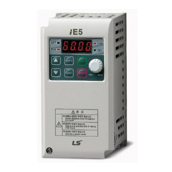
Thank you for purchasing LS Variable Frequency Drives!
Safety instructions are prepared to use the product safely and correctly by
preventing any accident or risk beforehand, so they should be always kept.
In this manual, safety instructions are divided into two classes; each has the
following meaning.
WARNING
CAUTION
Throughout this manual, we use the following two illustrations to make you
aware of safety considerations.
identifies potential hazards under certain conditions.
identifies shock hazards under certain conditions.
After reading this manual, keep it handy for any user to quickly refer to.
Read this manual carefully to user SV-iE5 Series Inverter's functions
appropriately and safely.
Do not remove the cover while the power is applied or the unit is in operation.
Or, it may cause electric shock.
Do not run the inverter with the front cover removed.
Or, it may cause an electric shock due to high voltage terminals or charged
capacitor exposure.
Do not remove the cover except for periodic inspections or wiring, even if the
input power is not applied.
Or, it may cause an electric shock due to charged capacitor exposure even if
the power is cut off.
Wiring and periodic inspections should be performed at least 10 minutes after
disconnecting the input power and after checking the DC link voltage is
discharged with a meter(below DC 30V).
Or, it may cause an electric shock (below DC 30V)
Operate the switches with dry hands.
Or, it may cause an electric shock.
SAFETY INSTRUCTIONS
Improper operation may result in serious personal injury or
death.
Improper operation may result in slight to medium personal
injury or property damage.
Warning
Instructions
i
Advertisement
Table of Contents

Related Manuals for LS Industrial Systems SV-iE5 Series


Summary of Contents for LS Industrial Systems SV-iE5 Series
-
Page 1: Safety Instructions
After reading this manual, keep it handy for any user to quickly refer to. Read this manual carefully to user SV-iE5 Series Inverter’s functions appropriately and safely. Warning Do not remove the cover while the power is applied or the unit is in operation. -
Page 2: Operating Precautions
Instructions Do not use the cable when its insulating tube is damaged. Or, it may cause an electric shock. Do not subject the cables to any heavy load stressful to them. Or, it may cause an electric shock due to damaged cable. Caution ... - Page 3 Instructions Ambient - 10 ~ 40 ℃ (non-freezing) temperature Relative humidity 90% RH or less (non-condensing) Storage - 20 ~ 65 ℃ Environment temperature Free of any corrosive gas, combustible gas, Service condition oil mist or dust Max. 1,000m above the sea level · Altitude, vibration 5.9m/sec²(=0.6g) or less (2) Wiring...
- Page 4 Instructions In case of input voltage unbalance, install AC reactor. Power Factor capacitors and generators may become overheated and damaged due to potential high frequency noise transmitted from inverter. Before operating unit and prior to user programming, reset user parameters to default settings.
- Page 5 User’s Manual The purpose of this manual is to provide the user with the necessary information to install, program, start up and maintain the SV-iE5 series inverter. To assure successful installation and operation of the SV-iE5 series inverter, the material presented must be thoroughly read and understood before proceeding ...
-
Page 6: Table Of Contents
Contents Contents 1. Basic Information and Precaution ..................1-1 Important precautions ........................ 1-1 Parts’ Names and Details ......................1-2 Assembling and Disassembling ....................1-3 2. Installation ..........................2-1 Installation precautions ......................2-1 Dimensions ..........................2-4 3. Wiring ............................ 3-1 Control Terminal Wiring Diagram ....................3-1 Power Terminal Wiring Diagram .................... -
Page 7: Basic Information And Precaution
Chapter 1. Basic Information and Precaution 1. Basic Information and Precaution Important precautions Unpack the package and check the inverter type, output ratings on Unpacking the nameplate and whether the inverter is intact. In addition, inspect the inverter for any damage that may have occurred during Inspection shipping. -
Page 8: Parts' Names And Details
Chapter 1. Basic Information and Precaution 1.2 Parts’ Names and Details Appearance Variable resistance for Status LED display frequency setting RUN button Front cover: Removed when wiring Cover screws and installing Inverter nameplate: Indicating the capacity and rating of the inverter ... -
Page 9: Assembling And Disassembling
Chapter 1. Basic Information and Precaution 1.3 Assembling and Disassembling To remove the front cover, press both indented sides of the cover lightly and pull it up. Remove the screw for wiring. Press the indented sides to remove the cover. ... - Page 10 Chapter 1. Basic Information and Precaution...
-
Page 11: Installation
Chapter 2. Installation 2. Installation 2.1 Installation precautions CAUTION Handle the inverter with care to prevent the plastic components damaged. Avoid installing the inverter in a place where vibration from bogie or press exists. Install in a location where ambient air temperature is within the permissible range (-10 ~ 40°C). - Page 12 Chapter 2. Installation Protect from high temperature and high moisture and/or direct sunlight. Install the inverter inside a “totally enclosed” panel to protect against oil mist, water or dust. When two or more inverters are installed inside a panel, the inverters and fans must be installed in proper positions with extreme care.
- Page 13 Chapter 2. Installation Warning Follows procedure below when Install the inverter for successful operation. iE5 has self cooling structure using air. Therefore install the Caution inverter vertically possible to air circulation. Malfunction or fire may be caused when installed horizontally. ...
-
Page 14: Dimensions
Chapter 2. Installation 2.2 Dimensions Inverter 001iE5-1 002iE5-1 004iE5-1 001iE5-2 002iE5-2 004iE5-2 φ Weight(kg) 0.44 0.46 0.68 0.43 0.45 0.67 Note Use M4 screw for fixing the inverter on a panel. -
Page 15: Wiring
Chapter 3. Wiring 3. Wiring 3.1 Control Terminal Wiring Diagram Description FX : forward run Multi RX : reverse run function EST : emergency stop Input RST : trip reset terminal JOG : jog operation 12V power(12V,100mA) for external volume Analogue frequency input(Voltage or current) Analogue output: 0 ~ 10V Input signal common... -
Page 16: Grounding Specification
Chapter 3. Wiring CAUTION Suitable For Use On A Circuit Capable of Delivering Not More Than 5000 RMS Symmetrical Amperes, 240 Volts Maximum. (UL508C) Use Copper Conductors Only, 75 °C only with a torque rating. (UL508C) Make sure the input power is off before wiring. ... -
Page 17: Control Terminal Wiring Specification
Chapter 3. Wiring 3.4 Control Terminal Wiring Specification Terminal description COM optional terminal AM CM Terminal description Wire size Torque [lb-in] Remarks P1~P5 Multi-function input T/M 1-5 22 AWG,0.3 mm Power T/M for external volume 22 AWG,0.3 mm resistance Analogue frequency input T/M 22 AWG,0.3 mm Multi-function output T/M 22 AWG,0.3 mm... -
Page 18: Pnp/Npn Modes Switch
Chapter 3. Wiring 3.5 PNP/NPN Modes Switch P1 P2 P3 P4 P5 Internal Power [NPN](up) Using internal P1 P2 P3 P4 P5 External power [PNP](down) Using external Voltage input[ V ] (right) Current input[ I ] (left) Analogue Analogue voltage input current input 1) Using external current... -
Page 19: Peripheral
Chapter 4. Peripheral 4. Peripheral 4.1 Configuration of Peripherals Correct peripherals must be selected and properly connected. An incorrectly applied or installed inverter may result in system malfunction or reduction in product life as well as component damage. You must read and understand this manual thoroughly before proceeding. -
Page 20: Recommended Mccb And Magnetic Contactor
Chapter 4. Peripheral 4.2 Recommended MCCB and Magnetic Contactor Model MCCB (LSIS) ELB (LSIS) MC (LSIS) 001iE5-1 002iE5-1 004iE5-1 ABS33c UTE100 EBS33c MC-6a 001iE5-2 002iE5-2 004iE5-2 4.3 Recommended Reactors Model AC Input fuse AC reactor DC reactor 001iE5-1 4.2mH, 3.5A 10mH, 3A 002iE5-1 004iE5-1... -
Page 21: Loader
Chapter 5. Loader 5. Loader 5.1 Configuration FWD/REV LED SET LED RUN LED 7-Segment LED UP, DOWN SHFT FUNC RUN, STOP/RESET Volume Resistance Note STOP key of the inverter iE5 also contains reset function, which is used to cancel trip. Trip may be cancelled by using this key. Display Description Remark... -
Page 22: Alpha-Numeric View On The Led
Chapter 5. Loader 5.2 Alpha-numeric view on the LED Refer to the below table summarizing the characters displayed on the LED. Inverter LED Inverter LED Eng. Inverter LED Eng. Inverter LED Eng. Note Inverter iE5 uses 7-segment display. Therefore, it displays numbers and alphabet as the above table. -
Page 23: Moving To Other Groups
Chapter 5. Loader 5.3 Moving to other groups There are two different parameter groups in SV-iE5 series as shown below. Drive group PG group Type Description Drive group Basic parameters necessary to operate the inverter; target frequency, acceleration/deceleration time and etc. -
Page 24: How To Move Among Codes In A Group
Chapter 5. Loader 5.4 How to move among codes in a group Moving between groups Moving from 15 of PG Group to Drive Group SHFT PG group Drive group -. Display Code 15 of PG Group. -. Press SHFT key. -. - Page 25 Chapter 5. Loader Code jump Moving from code 1(P 0) to the code15(P15) in PG Group -. It displays P0, the 1st code of Drive Group. -. Press FUNC key. -. SET lamp lights up. Changeable FUNC number blinks -.
- Page 26 Chapter 5. Loader Frequency setting When changing RUN frequency to 30.05 [Hz] in Drive Group FUNC SHFT FUNC Drive group -. It displays Target Frequency, the 1st code of Drive Group. -. Press FUNC key. -. SET lamp lights up. -.
-
Page 27: How To Set Parameters
Chapter 5. Loader 5.5 How to set parameters Parameter change in Drive Group Changing acceleration duration from 5.0 to 16.0 seconds FUNC FUNC Drive group SHFT SHFT -. It displays the target frequency, the 1st code of Drive Group. -. - Page 28 Chapter 5. Loader Parameter change in PG Group Changing P34, Code 34 of PG Group from 0 to 1 FUNC FUNC SHFT FUNC SHFT FUNC PG group -. The 1st code of PG Group is displayed. -. Press FUNC key. -.
-
Page 29: Monitoring Operation Status
Chapter 5. Loader 5.6 Monitoring Operation Status Displaying Current Output Monitoring output current in Drive Group FUNC FUNC Drive group -. The target frequency, Code 1 of Drive Group is displayed. -. Press UP() key or DOWN() key until Cur is displayed. -. - Page 30 Chapter 5. Loader Fault display How to monitor fault condition in Drive Group Accel Overcurrent trip Current Frequency FUNC Drive group STop -. OCt appears when an Overcurrent fault occurs. -. Press FUNC key. -. Press UP() key or DOWN () key. -.
- Page 31 Chapter 5. Loader When types of faults occur at the same time When Overcurrent(OCt), overvoltage(Ovt) overheat(OHt) occur simultaneously Overheating Overvoltage Overcurrent Drive -. When various trips occur simultaneously, it shows like the figure above and it can show up to 3 trips. Note In case inverter trip occurs, it shows the type in the current fault status indication code.
- Page 32 Chapter 5. Loader 5-12...
-
Page 33: Basic Operation
Chapter 6. Basic Operation 6. Basic Operation 6.1 Frequency Setting and Basic Operation Note The following parameters are set to factory defaults. Therefore, results may be different if any parameter is changed by a user. In this case, initialize parameters back to factory defaults and follow the instructions below. - Page 34 Chapter 6. Basic Operation If setting frequency with volume resistance on the loader and commanding operation on the inverter’s terminal Indication Operation and description -. Target frequency, the first code of Drive Group when turning it on. -. Press UP() key four times. -.
- Page 35 Chapter 6. Basic Operation If setting frq with volume resistance on the loader and commanding operation with RUN key on the loader Indication Operation and description -. Target frequency, the first code of Drive Group when turning it on. -.
- Page 36 Chapter 6. Basic Operation Wiring diagram Operating pattern 220 Vac L1 (R) 10 Hz L2 (S) Frequency SHFT STOP/RST FUNC STop...
-
Page 37: Function List
Chapter 7. Function List 7. Function List Adj. Min/Max Factory Display Name Description during range defaults This parameter sets the operation frequency. During stop, it displays Frequency Command; During run, it Frequency 0 ~ 200 shows output frequency. During multi- 0.00 command [Hz]... - Page 38 Chapter 7. Function List Drive Group Adj. Min/Max Factory Display Name Description during range defaults Output Display output current current No. of motor Display the no. of motor rotation rotation(RPM) Inverter DC Display DC voltage inside the voltage inverter Output Display the inverter’s output voltage...
- Page 39 Chapter 7. Function List Adj. Min/Max Factory Display Name Description during range defaults Jump code 0 ~ 88 Sets the code number to jump It logs the information on the types of faults, and the frequency, current and status such as acceleration, Fault log 1 deceleration and stop at the time of trouble.
- Page 40 Chapter 7. Function List Adj. Min/Max Factory Display Name Description during range defaults DC brake It sets the amount of DC voltage before 0 ~ 200 start a motor starts to run. Motor rated voltage current(P43) DC brake 0 ~ 60 It applies the current to a motor for the start time [sec]...
- Page 41 Chapter 7. Function List Adj. Min/Max Factory Display Name Description during range defaults Output 40 ~ It adjusts the amount of output voltage, voltage based on the percentage of input adjustment voltage. This parameter turns off the inverter Overload output when motor is overloaded. trip 0 ~ 1 Overload protection function works if it...
- Page 42 Chapter 7. Function List Min/Max Factory Adj. Display Name Description range defaults during run When run frequency is issued, motor starts to accelerate sfter dwell frequency is Dwell 0.1 ~ applied to the motor during dwell frequenc- 5.00 time(P32). [Hz] It can be set within max frequency(P16) and start frequency(P18).
- Page 43 Chapter 7. Function List Adj. Min/Max Factory Display Name Description during range defaults Speed 0 ~ 15 It is active to prevent any possible fault when search [bit] the inverter outputs its voltage to the running selectio- motor. Func Power Restart Operati Normal...
- Page 44 Chapter 7. Function List Adj. Min/Max Factory Display Name Description during range defaults It sets the number of restart tries after a fault occurs. Auto Restart is Number of deactivated if the fault outnumbers Auto 0 ~ 10 the restart tries. This function is Restart try active when [drv] is set to 1 or 2 {Run/Stop via control terminal}.
- Page 45 Chapter 7. Function List Adj. Min/Max Factory Display Name Description during range defaults 0 V/F control Control mode 0 ~ 2 1 Slip compensation control selection 2 PI control P gain for PI 0~ 999.9 300.00 controller It sets the gains for the PI controller’s I time for PI 0.1~32.0 response characteristics.
- Page 46 Chapter 7. Function List Adj. Min/Max Factory Display Name Description during range defaults It can monitoring on the rpm display Gain for Motor 1 ~ 1000 code of drive group as converting rpm display gear ratio of load system. Filter time Adjusts the responsiveness of constant for AI 0 ~ 9999...
- Page 47 Chapter 7. Function List Adj. Min/Max Factory Display Name Description during range defaults Multi-function 0 Forward run command (FX) input terminal 1 Reverse run command (RX) P1 define Multi-function EST-Emergency Stop Trip input terminal temporary output cut-off P2 define Multi-function 3 Reset when a fault occurs(RST) input terminal 4 Jog operation command (JOG)
- Page 48 Chapter 7. Function List Adj. Min/Max Factory Display Name Description during range defaults Filtering time If the value is set higher, the constant 1 ~ 20 responsiveness of the Input terminal is Multi-function getting slower. Input terminal Output item Output to 10[V] 0 Output freq.
- Page 49 Chapter 7. Function List Min/ Adj. Factory Display Name Description during defaults range Operation Operation Func when when the Operation setting the trip other when the low number of than voltage trip auto voltage trip occurs restart occurs try(P38) Fault bit 2 bit 1 bit 0...
- Page 50 Chapter 7. Function List Adj. Min/Max Factory Display Name Description during range defaults Sets communication parity and stop bit. Parity bit Stop bit 1 Stop Bit Parity/stop 0 ~ 3 bit setting 2 Stop Bit Odd Parity 1 Stop Bit Even Parity 1 Stop Bit Initialize the parameters set by a user...
-
Page 51: Troubleshooting And Maintenance
Chapter 8. Troubleshooting and Maintenance 8. Troubleshooting and Maintenance 8.1 Protective Functions Caution When a fault occurs, the cause must be corrected before the fault can be cleared. If protective function keeps active, the inverter should restart after clearing the cause(s). - Page 52 Chapter 8. Troubleshooting and Maintenance Protection of abnormal internal circuit and external signal Fault Protective Description display function Parameter Displayed when user-setting parameters fail to be entered save error into memory. Displayed when an error occurs in CPU operation and Inverter internal OS program.
-
Page 53: Fault Remedy
Chapter 8. Troubleshooting and Maintenance 8.2 Fault Remedy Caution If any trouble occurs due to overcurrent, make sure to restart after eliminating the causes because power semiconductor element inside the inverter may be broken. Protective Cause Remedy function Increase the Accel/Decel ... - Page 54 Chapter 8. Troubleshooting and Maintenance Fault Remedy Protective Cause Remedy function Make connection of magnetic Faulty contact of magnetic switch at output switch at output of the inverter Faulty output wiring securely. Output Phase Check output wiring. loss ...
-
Page 55: Precautions For Maintenance
Check the voltage between terminal P or P1 and N using a tester before proceeding. SV-iE5 series inverter has ESD (Electrostatic Discharge) sensitive components. Take protective measures against ESD before touching them for inspection or installation. -
Page 56: Parts Replacement
Chapter 8. Troubleshooting and Maintenance 8.5 Parts Replacement The inverter consists of many electronic parts such as semiconductor devices. The following parts may deteriorate with age because of their structures or physical characteristics, leading to reduced performance or failure of the inverter. For preventive maintenance, the parts must be changed periodically. -
Page 57: Specifications
Chapter 9. Specifications 9. Specifications 9.1 Technical data Input and output ratings Type : SV xxx iE5 – x 001-1 002-1 004-1 001-2 002-2 004-2 [HP] Motor [kW] Capacity[kVA] 0.95 1.14 Current [A] Output ratings Output frequency 0 ~ 200 [Hz] Voltage [V] 3phase 200 ~ 230V 1phase 200 ~ 230 VAC... - Page 58 Chapter 9. Specifications Operation Operation mode Select one of loader/terminal/COM operation(optional) Analogue: 0 ~ 10[V], 0 ~ 20[mA], loader volume Frequency setting Digital: loader Operation features PI, up-down, 3-wire NPN / PNP selectable (see page 3-5) Multi-function Functions: FWD/REV RUN, Emergency stop, Fault terminal reset, Jog operation, Multi-step Frequency-High &...
-
Page 59: Declaration Of Conformity
DECLARATION OF CONFORMITY... - Page 60 DECLARATION OF CONFORMITY TECHNICAL STANDARDS APPLIED The standards applied in order to comply with the essential requirements of the Directives 2006/95/CEE "Electrical material intended to be used with certain limits of voltage" and 2004/108/CEE "Electromagnetic Compatibility" are the following ones: •...
- Page 61 DECLARATION OF CONFORMITY EMI / RFI POWER LINE FILTERS LS inverters, iE5 series RFI FILTERS THE LS RANGE OF POWER LINE FILTERS FF ( Footprint ) - FE ( Standard ) SERIES, HAVE BEEN SPECIFICALLY DESIGNED WITH HIGH FREQUENCY LG INVERTERS. THE USE OF LS FILTERS, WITH THE INSTALLATION ADVICE OVERLEAF HELP TO ENSURE TROUBLE FREE USE ALONG SIDE SENSITIVE DEVICES AND COMPLIANCE TO CONDUCTED EMISSION AND IMMUNITY STANDARS TO EN 50081.
- Page 62 DECLARATION OF CONFORMITY...
- Page 63 UL Marking UL Marking 1. SHORT CIRCUIT RATING The drive is suitable for use in a circuit capable of delivering not more than 5,000A RMS at the drive’s maximum rated voltage. (L’entraînement convient pour une utilisation dans un circuit capable de délivrer pas plus de 5,000A RMS à...
- Page 64 EAC mark The EAC (EurAsian Conformity) mark is applied to the products before they are placed on the market of the Eurasian Customs Union member states. It indicates the compliance of the products with the following technical regulations and requirements of the Eurasian Customs Union: Technical Regulations of the Customs Union 004/2011 “On safety of low voltage equipment”...
- Page 65 WARRANTY WARRANTY Installation Maker LSIS Co.,Ltd (start-up) date Model No. SV-iE5 Warranty period Name Customer Address info Tel. Name Sales Address office Tel. Note This product has been manufactured through the strict QC control and inspection of LSIS. Warranty period is 12 months after installation or 18 months after manufactured when the installation date is unidentified.
- Page 66 Manual Revision History Manual Revision History Revision Changes Version. No Remarks Sept 2006 First edition 1.10 Jan 2007 Contents revised 1.10 Apr 2007 Contents revised 1.20 Jul 2008 Contents revised 1.30 Sustainable Management LS Industrial System Co.,Ltd take the highest priority on sustainable management and do our best to preserve the environment of the earth.
Need help?
Do you have a question about the SV-iE5 Series and is the answer not in the manual?
Questions and answers
Not working help me
Common troubleshooting steps for the LS Industrial Systems SV-iE5 Series include:
1. Overcurrent Protection:
- Increase Accel/Decel time if it's too short for the load inertia.
- Replace the inverter if the load exceeds its rating.
- Stop the motor before inverter output or use the speed search (P36).
- Check output wiring for short circuits or ground faults.
- Inspect the motor’s mechanical brake for proper operation.
2. Ground Fault Current:
- Check output terminal wiring for ground faults.
- Replace the motor if the insulation is damaged due to heat.
- Upgrade the motor and inverter capacity or reduce the load if it's too high.
3. Inverter Overload:
- Reduce the torque boost scale if it's set too high.
4. Restarting After Faults:
- Eliminate the cause before restarting to avoid damage to the inverter’s power semiconductor.
These steps help identify and fix issues related to motor start-up, overcurrent, ground faults, and overloads.
This answer is automatically generated