
Related Manuals for Spectrasensors SS500


Summary of Contents for Spectrasensors SS500
- Page 1 SS500/SS2000 SS3000 H SS3000 H O/CO SS500/SS2000/SS3000 Gas Analyzer Hardware Installation and Maintenance Manual P/N 4900002215 rev D...
- Page 2 Hardware Installation and Maintenance Manual...
- Page 3 Fax: 713.856.6623 www.spectrasensors.com Copyright © 2016 SpectraSensors, Inc. No part of this manual may be reproduced in whole or in part without the express written permission of SpectraSensors, Inc. SpectraSensors reserves the right to change product design and specifications at any...
-
Page 4: Revision History
Revision History Revision Engineering Order Date EO15547 4/8/2014 ECR16086 3/10/2015 ECR16353 1/22/2016 ECR16701 7/29/2016... -
Page 5: Table Of Contents
SpectraSensors Overview ........ - Page 6 SS500/SS2000/SS3000 Analyzer Peak Tracking Reset Procedure ........B-3 Cleaning the Mirrors .
-
Page 7: List Of Figures
Drawing of typical full-featured single-channel SCS (SS500/SS2000) ........A-8 Figure A–4. - Page 8 SS500/SS2000/SS3000 Analyzer Figure A–10. Drawing of typical full-featured dual-channel, dual-stream SCS (SS3000) ........A-15 Figure A–11.
- Page 9 ..A-5 Table A–6. Replacement parts for SS500/SS2000/SS3000 analyzers ..A-19 Table B–1. Potential instrument problems and solutions ....B-16...
- Page 10 SS500/SS2000/SS3000 Analyzer THIS PAGE INTENTIONALLY LEFT BLANK 4900002215 rev. D 7-29-16...
-
Page 11: Who Should Read This Manual
Contents. There are a number of options and accessories available for the SS500/SS2000/SS3000 analyzers. This manual has been written to address the most common options and accessories. Images, tables and charts have been included to provide a visual understanding of the analyzer and its functions. - Page 12 SS500/SS2000/SS3000 Analyzer Failure to follow all directions may result in damage or malfunction of the analyzer. INVISIBLE LASER RADIATION - Avoid CAUTION exposure to beam. Class 3b Radiation Product. CLASS 3B INVISIBLE LASER Refer servicing to the manufacturer or qualified RADIATION WHEN OPEN personnel.
-
Page 13: Conventions Used In This Manual
Headquartered in Houston, Texas, SpectraSensors was incorporated in 1999 as a spin-off of the NASA/Caltech Jet Propulsion Laboratory (JPL) for the purpose of commercializing space-proven measurement technologies initially developed at JPL. SpectraSensors was acquired by the Endress + Hauser Group in 2012, which has expanded our reach in the global marketplace. -
Page 14: Figure 1-1 Ss500/Ss2000 Analyzer
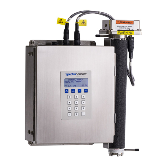
SS500/SS2000/SS3000 Analyzer performance specifications, refer to Table A–1 through Table A–3 and Figure 1–1 for an image of a standard SS500/SS2000 with a 0.8-m cell. Figure 1–1 SS500/SS2000 analyzer The SS3000 is a dual-channel version of the SS2000 and is usually configured... -
Page 15: How The Analyzers Work
With the SS500/SS2000/SS3000 analyzers, sample gas flows continuously through the sample cell ensuring that the sample is always representative of the flow in the main pipe. -
Page 16: Figure 1-4 Typical Raw Signal From A Laser Diode Absorption Spectrometer With And Without Mirror Contamination
SS500/SS2000/SS3000 Analyzer to the Beer-Lambert absorption law, the intensity remaining, I(), as measured by the detector at the end of the beam path of length I (cell length x number of passes), is given by I exp lN –... -
Page 17: Wavelength Modulation Spectroscopy (Wms) Signal Detection
Wavelength Modulation Spectroscopy (WMS) Signal Detection SpectraSensors takes the fundamental absorption spectroscopy concept a step further by using a sophisticated signal detection technique called wavelength modulation spectroscopy (WMS). When employing WMS, the laser drive current is modulated with a kHz sine wave as the laser is rapidly tuned. -
Page 18: Getting Familiar With The Analyzer
(depending on target and background species) at real-time response rates (on the order of 1 second). All SpectraSensors TDL gas analyzers employ the same design and hardware platform. Measuring different trace gases in various mixed hydrocarbon background streams is accomplished by selecting a different optimum diode laser wavelength between 750-3000nm, which provides the least amount of sensitivity to background stream variations. -
Page 19: Figure 1-7 Analyzer Overview (Ss3000 Pictured)
Inside the SS500/SS2000 analyzer electronics enclosure is the electronics assembly as shown in Figure 1–8 and Figure 1–9. Inside the SS3000 analyzer electronics enclosure is the electronics assembly as shown in Figure 1–10 and Figure 1–11. -
Page 20: Figure 1-8. Electronics Control Board (Ac) For Single-Channel Systems (Ss500/Ss2000)
BOARD BACKPLANE FUSE (F1) COMPONENT GROUND CUSTOMER GROUND PROTECTIVE GROUND 4-20 mA & SERIAL SIGNAL CONNECTIONS ASSIGNABLE ALARM RELAY GENERAL FAULT ALARM RELAY COMMON Figure 1–8 Electronics control board (AC) for single- channel systems (SS500/SS2000) – 4900002215 rev. D 7-29-16... -
Page 21: Figure 1-9 Electronics Control Board (Dc) For Single-Channel Systems (Ss500/Ss2000)
SUPPLY BACKPLANE FUSE (F2) COMPONENT GROUND PROTECTIVE GROUND CUSTOMER GROUND 4-20 mA & SERIAL SIGNAL CONNECTIONS ASSIGNABLE ALARM FAULT GENERAL FAULT ALARM FAULT COMMON Figure 1–9 Electronics control board (DC) for single-channel systems (SS500/SS2000) – Hardware Installation and Maintenance Manual... -
Page 22: Figure 1-10. Electronics Control Board (Ac) For Dual-Channel Systems (Ss3000)
SS500/SS2000/SS3000 Analyzer TEMPERATURE 4-20 mA CURRENT LOOP CONTROL BOARD BOARD (STACKED) LASER POWER DRIVER SUPPLY BOARD BACKPLANE FUSE (F1) COMPONENT GROUND PROTECTIVE GROUND CUSTOMER GROUND 4-20 mA & SERIAL SIGNAL ASSIGNABLE CONNECTIONS ALARM RELAY (Ch. A) GENERAL FAULT ALARM RELAY (Ch. A) -
Page 23: Figure 1-11. Electronics Control Board (Dc) For Dual-Channel Systems (Ss3000)
Introduction TEMPERATURE 4-20 mA CURRENT LOOP CONTROL BOARD BOARD (STACKED) LASER DRIVER BOARD POWER SUPPLY BACKPLANE FUSE (F2) COMPONENT GROUND CUSTOMER GROUND PROTECTIVE GROUND 4-20 mA & SERIAL SIGNAL ASSIGNABLE CONNECTIONS ALARM RELAY (Ch. A) GENERAL FAULT ALARM RELAY (Ch. A) ASSIGNABLE ALARM RELAY (Ch. - Page 24 SS500/SS2000/SS3000 Analyzer THIS PAGE INTENTIONALLY LEFT BLANK – 4900002215 rev. D 7-29-16...
-
Page 25: What Should Be Included In The Shipping Box
• Documentation media, which includes this manual and other system manuals • One (SS500 or SS2000) or two (SS3000) external serial cable(s) to connect the analyzer to a computer • Additional accessories or options as ordered. If any of these contents are missing, consult “Customer Service” on page B-21. -
Page 26: Installing The Analyzer
Crescent wrench • 9/16” open-end wrench Mounting the Analyzer The SS500/SS2000/SS3000 analyzer is manufactured for wall or Unistrut ® equivalent) metal framing installations. Depending on your application and configuration, the analyzer may come premounted on a SCS panel to be mounted on a wall or Unistrut framing, or without a panel requiring mounting –... -
Page 27: Lifting/Carrying The Analyzer
Lifting/carrying the analyzer At approximately 25 lbs (11.5 Kg), the SS500/SS2000/SS3000 can easily be lifted from the packaging and moved to the installation location. Take care not to lift or carry the analyzer by the measurement cells or the cables connected at the top of the analyzer, or damage may occur. -
Page 28: Protective Chassis And Ground Connections
SS500/SS2000/SS3000 Analyzer be performed by personnel qualified in electrical conduit installation. Conduit seals should be used where appropriate in compliance with local regulations. Hazardous voltage and risk of electric shock. Before attaching the wiring to the analyzer, make sure all power to the wires is off. -
Page 29: Figure 2-1. Internal View Of Electronics Enclosure (Ss500)
Conduit seals should be used where appropriate in compliance with local regulations. Figure 2–1 Internal view of electronics enclosure (SS500) Because the breaker in the power distribution panel or switch will be the primary means of disconnecting the power from the... -
Page 30: Connecting The Output Signals
SS500/SS2000/SS3000 Analyzer For DC systems, connect the minus wire to the terminal marked “” and the positive wire to the terminal marked “+” as shown in Figure 2–2. — NEU LINE AC TERMINAL BLOCK DC TERMINAL BLOCK Figure 2–2 AC and DC connection terminal blocks in electronics enclosure 6. -
Page 31: Figure 2-3 Mating Terminal Block (Tb2) In Electronics Enclosure For Connecting Signal Cables
Conduit seals should be used where appropriate in compliance with local regulations. 3. Pull the customer-supplied cable(s) for the current loop(s), digital output relays, and the SpectraSensors external serial cable(s) (included in the shipping box) through the conduit into the electronics enclosure. -
Page 32: Changing The 4-20 Ma Current Loop Mode
SS500/SS2000/SS3000 Analyzer Table 2–1 Output signal connections Terminal Description D-Conn Color Ch. A Serial RX Pin-3 Black Ch. A Serial TX Pin-2 COM Serial Ground Pin-5 Shield Ch. B Serial RX Pin-3 Black Ch. B Serial TX Pin-2 Ch. A Current Loop + Ch. -
Page 33: Calibrating The Analog Output
Installation Potentiometers JMP1 Figure 2–4 4-20 mA output board 4. For 4-20 mA sink, carefully replace the jumper to connect the center hole with point “P.” Needle nose pliers may be required to remove the jumper. 5. Repeat steps 2-4 as necessary for any remaining 4-20 mA boards. 6. -
Page 34: Testing And Adjusting The 4-20 Ma Zero And Span
Personnel should have a thorough knowledge and understanding of the physical properties and safety precautions for the sample contents before installing the SCS. SpectraSensors recommends using 1/4” O.D x 0.035” wall thickness, seamless stainless steel tubing. – 4900002215 rev. D 7-29-16... - Page 35 Installation To connect the sample supply line: 1. First, confirm that the sample probe is correctly installed at the process supply tap and that the sample probe isolation valve is closed. Consult sample probe manufacturer instructions for proper installation procedures. The process sample at the sample tap may be at a high pressure.
- Page 36 Secure tubing to appropriate structural supports as required. 9. Check all connections for gas leaks. SpectraSensors recommends using a liquid leak detector. Do not exceed 10 PSIG (0.7 barg) in sample cell. Damage to cell may result.
-
Page 37: Conditioning The Scs Tubing
Installation 6. Check all connections for gas leaks. SpectraSensors recommends using a liquid leak detector. Do not exceed 10 PSIG (0.7 barg) in sample cell. Damage to cell may result. 7. Be sure to vent the bypass return port and pressure relief vent port (if applicable) in a similar fashion when the unit is in use. - Page 38 SS500/SS2000/SS3000 Analyzer THIS PAGE INTENTIONALLY LEFT BLANK – 4900002215 rev. D 7-29-16...
- Page 39 Make sure that the field pressure reducing regulator is equipped with an appropriate pressure relief valve. SS500/SS2000/SS3000 systems may be ordered with an optional integrated Sample Conditioning System (SCS). Each SCS has been specifically designed to deliver a sample stream to the analyzer that is representative of the process stream at the time of sampling.
-
Page 40: About The Scs
Figure 3–1 Typical full-featured, single-channel SCS (SS500/SS2000) on a panel – 4900002215 rev. D 7-29-16... -
Page 41: Checking The Scs Installation
Sample Conditioning System (SCS) The flow exiting the bypass loop is combined with the flow exiting the measurement cell and sent out the sample return port to be vented to a safe location. Checking the SCS Installation Before operating the system for the first time, a careful check of the installation of the entire SCS from the sample probe to the vent is recommended. - Page 42 SS500/SS2000/SS3000 Analyzer 2. If applicable, confirm that the sample supply line electric tracer temperature controller at the tracer control system is set to the temperature specified. 3. If applicable, confirm proper heating of the sample supply tubing. 4. Confirm that all sample system shut-off valves are closed.
-
Page 43: Shutting Down The Scs
Sample Conditioning System (SCS) 4. Open the bypass flowmeter control valve to establish sample flow from the sample probe and set the flowmeter to the specified value. Do not exceed 10 PSIG at any time in the cell. Refer to Appendix A for analyzer specifications. - Page 44 SS500/SS2000/SS3000 Analyzer The process sample at the sample tap is at a high pressure. A pressure reducing regulator is located at the sample tap to reduce the sample pressure and enable operation of the SCS at a low pressure. Use extreme caution when operating the sample probe isolation valve and field pressure reducing regulator.
- Page 45 Sample Conditioning System (SCS) 4. Turn off power to the analyzer. If the system will not be out of service for an extended period, it is advised that power remain applied to the sample transport line electric tracer, if applicable. To isolate the analyzer for long-term shutdown: If the analyzer is to be out of service for an extended period, the analyzer must be isolated at the process sample tap.
- Page 46 SS500/SS2000/SS3000 Analyzer 5. Close the field pressure reducing regulator (adjustment knob turned fully counterclockwise). 6. Close the sample supply shut-off valve. 7. Leave the flowmeter control valves open. 8. Close the atmospheric vent header shut-off valve for the sample bypass and measurement cell effluent from the SCS.
-
Page 47: Appendix A: Specifications
Appendix A: Specifications Table A–1 SS500 H O analyzer specifications Performance Refer to Calibration Report Concentration Repeatability Refer to Calibration Report Accuracy Refer to Calibration Report 1 second Measurement Update Time Application Data Environmental Temperature Range -4 to 122 °F (-20 to 50 °C) -
Page 48: Table A-2 Ss2000 Single-Channel H
SS500/SS2000/SS3000 Analyzer Table A–2 SS2000 single-channel H O analyzer specifications Performance Refer to Calibration Report Concentration Repeatability Refer to Calibration Report Accuracy Refer to Calibration Report 1 second Measurement Update Time Application Data Environmental Temperature Range -4 to 122 °F (-20 to 50 °C) Environmental Relative Humidity 80% for temperatures up to 31°C MAX... -
Page 49: Table A-3 Ss2000 Single-Channel Co
Specifications Table A–3 SS2000 single-channel CO analyzer specifications Performance Refer to Calibration Report Concentration Repeatability Refer to Calibration Report Accuracy Refer to Calibration Report 1 second Measurement Update Time Application Data Environmental Temperature Range -4 to 122 °F (-20 to 50 °C) Environmental Relative Humidity 80% for temperatures up to 31°C MAX Altitude... -
Page 50: Table A-4 Ss3000 Dual Channel H
SS500/SS2000/SS3000 Analyzer Table A–4 SS3000 dual channel H O analyzer specifications Performance Refer to Calibration Report Concentration Repeatability Refer to Calibration Report Accuracy Refer to Calibration Report 1 second Measurement Update Time Application Data Environmental Temperature Range -4 to 122 °F (-20 to 50 °C) 15 to 140 °F (-10 to 60 °C) - Optional... -
Page 51: Table A-5 Ss3000 Dual Channel H
Specifications Table A–5 SS3000 dual channel H O/CO analyzer specifications Performance Refer to Calibration Report Concentration (H Repeatability (H Refer to Calibration Report Refer to Calibration Report Concentration (CO Repeatability (CO Refer to Calibration Report Accuracy Refer to Calibration Report 1 second Measurement Update Time Application Data... -
Page 52: Figure A-1 Ss500/Ss2000 0.8-M Cell (Moisture) Outline And Mounting Dimensions
SS500/SS2000/SS3000 Analyzer Figure A–1 SS500/SS2000 0.8-m cell (moisture) outline and mounting dimensions – 4900002215 rev. D 7-29-16... -
Page 53: Figure A-2 Ss500/Ss2000 0.1-M Cell (Carbon Dioxide) Outline And Mounting Dimensions
Specifications Figure A–2 SS500/SS2000 0.1-m cell (carbon dioxide) outline and mounting dimensions – Hardware Installation and Maintenance Manual... -
Page 54: Figure A-3. Drawing Of Typical Full-Featured Single-Channel Scs
Figure A–3 Drawing of typical full-featured single-channel SCS (SS500/SS2000) -
Page 55: Figure A-4 Drawing Of Typical Full-Featured Single-Channel Scs (Ss500/Ss20000) In 24X24 Enclosure
Figure A–4 Drawing of typical full-featured single-channel SCS (SS500/SS20000) in 24x24 enclosure... -
Page 56: Figure A-5 Drawing Of Typical Full-Featured Single-Channel Scs (Ss500/Ss20000) In 30X30 Enclosure
Figure A–5 Drawing of typical full-featured single-channel SCS (SS500/SS20000) in 30x30 enclosure... -
Page 57: Figure A-6 Electrical Schematic For Ss500/Ss2000
PROCESSOR PROCESSOR 120/240 CH. A 120/240 VAC 4-20 mA/RS232 SIGNAL ANALYZER POWER OUTPUT INPUT Figure A–6 Electrical schematic for SS500/SS2000... -
Page 58: Figure A-7. Interconnect Diagram For Single-Channel System (Ss500/Ss2000
Figure A–7 Interconnect diagram for single-channel system (SS500/SS2000) -
Page 59: Figure A-8 Ss3000 0.8-M/0.1-M Cells
Specifications Figure A–8 SS3000 0.8-m/0.1-m cells (H O/ CO outline and mounting dimensions – Hardware Installation and Maintenance Manual... -
Page 60: Figure A-9 Ss3000 0.8-M/0.8-M Cells
SS500/SS2000/SS3000 Analyzer Figure A–9 SS3000 0.8-m/0.8-m cells (H outline and mounting dimensions – 4900002215 rev. D 7-29-16... -
Page 61: Figure A-10. Drawing Of Typical Full-Featured Dual-Channel, Dual-Stream Scs
Figure A–10 Drawing of typical full-featured dual-channel, dual-stream SCS (SS3000) -
Page 62: Figure A-11 Drawing Of Typical Full-Featured Dual-Channel, Dual-Stream Scs (Ss3000) In A 36 X 36 Enclosure
Figure A–11 Drawing of typical full-featured dual-channel, dual-stream SCS (SS3000) in a 36 X 36 enclosure... -
Page 63: Figure A-12 Electrical Schematic For Ss3000
TO CH. B TO CH. A PROCESSOR PROCESSOR TO CH. A & CH. B PROCESSORS 120/240 CH. B CH. A R4 R3 R2 CH. A CH. B 120/240 VAC ANALYZER POWER 4-20 mA/RS-232 SIGNAL INPUT OUTPUT Figure A–12 Electrical schematic for SS3000... -
Page 64: Figure A-13. Interconnect Diagram For Dual-Channel System (Ss3000
Figure A–13 Interconnect diagram for dual-channel system (SS3000) -
Page 65: Spare Parts
Specifications Spare Parts Below is a list of spare parts for the SS500/SS2000/SS3000 analyzers with recommended quantities for 2 years of operation. Due to a policy of continuous improvement, parts and part numbers may change without notice. Not all parts listed are included on every analyzer. - Page 66 SS500/SS2000/SS3000 Analyzer Table A-6 Replacement parts for SS500/SS2000/SS3000 analyzers (Continued) 2 YR Part Number Description Sample Conditioning Systems 61303042S4 Ball Valve, 1/4” TF (SS) 6100002193 Membrane & O-Ring, Membrane Separator 2800002057 Membrane Separator Cover O-ring, Viton 6101671208 Membrane Separator, 1/4” FNPT (SS)
-
Page 67: Appendix B: Maintaining & Troubleshooting
Appendix B: Maintaining & Troubleshooting This section presents recommendations and solutions to common problems, such as gas leaks, contamination, excessive sampling gas temperatures and pressures, and electrical noise. If your analyzer does not appear to be hampered by one of issues discussed in this chapter, contact “Customer Service”... -
Page 68: Explosion Hazard
Do not use plastic tubing of any kind for sample lines. Plastic tubing is permeable to moisture and other substances which can contaminate the sample stream. SpectraSensors recommends using 1/4” O.D x0.035” wall thickness, seamless stainless steel tubing. -
Page 69: Excessive Sampling Gas Temperatures And Pressures
5. Once the sampling line is completely free of solvent, reconnect the gas sampling line to the supply port of the analyzer. 6. Check all connections for gas leaks. SpectraSensors recommends using a liquid leak detector. Excessive Sampling Gas Temperatures and... -
Page 70: Determining The Type Of Cell Mirror
SS500/SS2000/SS3000 Analyzer Do not attempt to clean the cell mirror until you have consulted with your factory service representative and have been advised to do so. The sample cell assembly contains a low-power, 10 mW MAX, CW Class 3b invisible laser with a wavelength between 700-3000 nm. -
Page 71: Figure B-2 Stainless Steel Mirror Marking
Maintaining & Troubleshooting 1. Feel at the bottom of the cell for the engraved “X” marking or the side of the mirror for a groove. Refer to Figure B–2 below. MIRROR MARKED MIRROR GROOVED WITH ‘X’ RIM - SIDE VIEW Figure B–2 Stainless steel mirror marking a. - Page 72 6. Look inside the sample cell at the top mirror using a flashlight to ensure that there is no contamination on the top mirror. Due to its proximity to the optical head, SpectraSensors does not recommend cleaning the top mirror. If the top mirror is visibly contaminated, contact your factory service representative.
-
Page 73: To Replace The Stainless Steel Mirror
Maintaining & Troubleshooting 11. With gentle, uniform pressure, wipe the mirror from one edge to the other with the cleaning cloth only once and only in one direction to remove the contamination. Discard the cloth. Never rub an optical surface, especially with dry tissues, as this can mar or scratch the coated surface. -
Page 74: Pressure Sensor Replacement
SS500/SS2000/SS3000 Analyzer 4. Gently remove the mirror assembly from the cell by removing the socket-head cap screws and set on a clean, stable and flat surface. The sample cell assembly contains a low-power, 10 mW MAX, CW Class 3b invisible laser with a wavelength between 750-3000 nm. - Page 75 Maintaining & Troubleshooting • Pressure sensor not responding to pressure change • Physical damage to the pressure sensor Use the following information to replace a pressure sensor. Tools and materials: • 9/16” wrench • 7/8” wrench • 9-64” Allen wrench •...
-
Page 76: Figure B-4 Analyzer Component Locations
SS500/SS2000/SS3000 Analyzer CIRCULAR CIRCULAR CELL INLET CONNECTORS CONNECTORS PRESSURE SENSOR MEASUREMENT CELL CELL MOUNTING INLET MOUNTING BRACKETS BRACKETS (TOP & BOTTOM (BOTH SIDES) BOTH SIDES) MEASUREMENT CELL MEASUREMENT CELL CELL OUTLET CELL OUTLET SS500/SS2000 SS3000 Figure B–4 Analyzer component locations 6. -
Page 77: Figure B-6. Removing The Old Pressure Sensor
Maintaining & Troubleshooting Orient the measurement cell to avoid any debris from entering the cell. 12. Using a 9/16” wrench, secure the flange while using a 7/8” wrench to remove the old pressure sensor. Refer to Figure B–6. Figure B–6 Removing the old pressure sensor a. -
Page 78: Customer Service
SS500/SS2000/SS3000 Analyzer Threads showing signs of galling indicate a possible leak. Refer to “Customer Service” on page B-21 to arrange for repair. 14. Remove the new pressure sensor from the packaging. Retain the black connector cap on the sensor - do not remove. -
Page 79: Figure B-10. Newly Installed Pressure Sensor Positioning
Maintaining & Troubleshooting 18. Using the 9/16” wrench to hold the flange in place, turn the sensor clockwise with a 7/8” wrench until tight. Two or three threads on the pressure sensor should still be visible. Make sure the black connector at the bottom of the pressure sensor is facing up from the measurement cell. -
Page 80: Periodic Scs Maintenance
SS500/SS2000/SS3000 Analyzer 27. Reconnect the optical cable harness. 28. Turn the system power on. Refer to the Firmware Manual for this analyzer for “Powering up the analyzer.” 29. Run a validation on the analyzer. Refer to the Firmware Manual for instructions to “Start Validation.”... -
Page 81: Regular Scs Status Check
1. Shut down the system following the procedure in “Shutting Down the SCS” on page 3-5. 2. Inspect, repair or replace the filter as required. For additional information, contact SpectraSensors’ Technical Service Group at 800-619-2861. 3. Restart the system following the procedure in “Starting up the SCS”... -
Page 82: Table B-1 Potential Instrument Problems And Solutions
B-6. Possible alignment problem. Contact a factory sales representative for service information. Capture diagnostic data and send the file to SpectraSensors (see “To read diagnostic data with HyperTermi- nal” in the Firmware Manual for this analyzer). –... - Page 83 Null Fail Error fault. Move the jumper JMP1 on the electron- ics main board next to the pre-pot. Capture diagnostic data and send the file to SpectraSensors (see “To read diagnostic data with HyperTermi- nal” in the Firmware Manual for this analyzer).
- Page 84 See “Adjusting Analyzer Reading to fixed amount Match Specific Standard(s)” in the Firmware Manual for this analyzer. Capture diagnostic data and send the file to SpectraSensors (see “To read diagnostic data with HyperTermi- nal” in the Firmware Manual for this analyzer). –...
- Page 85 Check for contamination in the sample system, especially if the readings are much higher than expected. Capture diagnostic data and send the file to SpectraSensors (see “To read diagnostic data with HyperTermi- nal” in the Firmware Manual for this analyzer).
- Page 86 Match Specific Standard(s)” in the Firmware Manual for this analyzer. Capture diagnostic data and send the file to SpectraSensors (see “To read diagnostic data with HyperTermi- nal” in the Firmware Manual for this analyzer). Reading seems to always be high by a See “Adjusting Analyzer Reading to...
-
Page 87: Service Contact
Hours: Service engineers are on duty Monday-Friday, 8:00 a.m. to 5:00 p.m. Central Time. For SpectraSensors International Service, please contact the SpectraSensors distributor or the E+H Sales Center in your area, or contact: Phone: +1-713-466-3172, and press 2 for Technical Service Fax: +1-713-856-6623 E-mail: techsupport@spectrasensors.com... -
Page 88: Packing
SS500/SS2000/SS3000 Analyzer Packing SpectraSensors analyzer systems and auxiliary equipment are shipped from the factory in appropriate packaging. Depending on the size and weight, the packaging may consist of a cardboard-skinned container or a wooden crate. All inlets and vents are capped and protected when packaged for shipment. -
Page 89: Storage
Disclaimers SpectraSensors accepts no responsibility for consequential damages arising from the use of this equipment. Liability is limited to replacement and/or repair of defective components. This manual contains information protected by copyright. No part of this guide may be photocopied or reproduced in any form without prior written consent from SpectraSensors. - Page 90 SS500/SS2000/SS3000 Analyzer THIS PAGE INTENTIONALLY LEFT BLANK – 4900002215 rev. D 7-29-16...
-
Page 91: Index
NDEX Numerics Gas temperature B-15 Excessive sampling gas temperature B-3 4-20 mA current loop 2-6 Faults Null Fail Error B-17 Absorption profile 1-6 P/T Fail Error B-3 B-17 Acetone B-3 Power Fail Error B-2 B-16 Acetone-impenetrable gloves B-5 Spectrum Fail Error B-17 Track Fail Error B-3 B-18 Analyzer shutdown... - Page 92 SS500/SS2000/SS3000 Analyzer Serial connection 2-6 Service contact B-21 B-22 Signal wires 2-7 Natural frequencies 1-5 Stainless steel tubing 2-10 2-12 System conditioning 2-13 System models SS2000 1-3 SS3000 1-4 Optional analyzer hood 2-3 SS500 1-3 Outline schematic A-8 A-10 A-12...
Need help?
Do you have a question about the SS500 and is the answer not in the manual?
Questions and answers