Sign In
Upload
Manuals
Brands
SpectraSensors Manuals
Measuring Instruments
SS2000
SpectraSensors SS2000 Manuals
Manuals and User Guides for SpectraSensors SS2000. We have
2
SpectraSensors SS2000 manuals available for free PDF download: Installation And Maintenance Manual, Operator's Manual
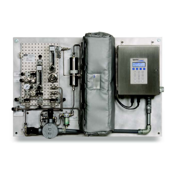
SpectraSensors SS2000 Installation And Maintenance Manual (92 pages)
GAS ALALYZER
Brand:
SpectraSensors
| Category:
Measuring Instruments
| Size: 5 MB
Table of Contents
Revision History
4
Table of Contents
5
List of Figures
7
1 : Introduction
11
List of Tables
11
Who Should Read this Manual
11
How to Use this Manual
11
General Warnings and Cautions
11
Conventions Used in this Manual
13
Spectrasensors Overview
13
About the Gas Analyzers
13
Differences between the SS500, SS2000, and SS3000
13
Figure 1-1 SS500/SS2000 Analyzer
14
Figure 1-2 SS3000 Analyzer
14
How the Analyzers Work
15
Figure 1-3 Schematic of a Typical Laser Diode Absorption Spectrometer
15
Figure 1-4 Typical Raw Signal from a Laser Diode Absorption Spectrometer with and Without Mirror Contamination
16
Figure 1-5 Typical Normalized Absorption Signal from a Laser Diode Absorption Spectrometer
17
Wavelength Modulation Spectroscopy (WMS) Signal Detection
17
Getting Familiar with the Analyzer
18
Figure 1-7 Analyzer Overview (SS3000 Pictured)
19
Table 1-1 Fuse Specifications
19
Figure 1-8. Electronics Control Board (AC) for Single-Channel Systems (SS500/SS2000)
20
Figure 1-9 Electronics Control Board (DC) for Single-Channel Systems (SS500/SS2000)
21
Figure 1-10. Electronics Control Board (AC) for Dual-Channel Systems (SS3000)
22
Figure 1-11. Electronics Control Board (DC) for Dual-Channel Systems (SS3000)
23
2 : Installation
25
What Should be Included in the Shipping Box
25
Inspecting the Analyzer
25
Installing the Analyzer
26
Hardware and Tools for Installation
26
Hardware
26
Tools
26
Mounting the Analyzer
26
Lifting/Carrying the Analyzer
27
Connecting Electrical Power to the Analyzer
27
Protective Chassis and Ground Connections
28
Figure 2-1. Internal View of Electronics Enclosure (SS500)
29
Connecting the Output Signals
30
Figure 2-2 AC and DC Connection Terminal Blocks in Electronics Enclosure
30
Figure 2-3 Mating Terminal Block (TB2) in Electronics Enclosure for Connecting Signal Cables
31
Changing the 4-20 Ma Current Loop Mode
32
Table 2-1 Output Signal Connections
32
Calibrating the Analog Output
33
Figure 2-4 4-20 Ma Output Board
33
Testing and Adjusting the 4-20 Ma Zero and Span
34
Connecting the Gas Lines
34
Conditioning the SCS Tubing
37
3 : Sample Conditioning System (SCS)
40
About the SCS
40
Figure 3-1. Typical Full-Featured, Single-Channel SCS (SS500/SS2000)
40
Checking the SCS Installation
41
Starting up the SCS
41
Shutting down the SCS
43
Appendix A: Specifications
47
Table A-1. SS500 H
47
Table A-2 SS2000 Single-Channel H
48
O Analyzer Specifications
48
Table A-3 SS2000 Single-Channel CO
49
Analyzer Specifications
49
Table A-4 SS3000 Dual Channel H
50
Table A-5 SS3000 Dual Channel H
51
CO 2 Analyzer Specifications
51
Figure A-1 SS500/SS2000 0.8-M Cell (Moisture) Outline and Mounting Dimensions
52
Figure A-2 SS500/SS2000 0.1-M Cell (Carbon Dioxide) Outline and Mounting Dimensions
53
Figure A-3. Drawing of Typical Full-Featured Single-Channel SCS
54
Figure A-4 Drawing of Typical Full-Featured Single-Channel SCS (SS500/SS20000) in 24X24 Enclosure
55
Figure A-5 Drawing of Typical Full-Featured Single-Channel SCS (SS500/SS20000) in 30X30 Enclosure
56
Figure A-6 Electrical Schematic for SS500/SS2000
57
Figure A-7. Interconnect Diagram for Single-Channel System (SS500/SS2000
58
Figure A-8 SS3000 0.8-M/0.1-M Cells
59
Figure A-9 SS3000 0.8-M/0.8-M Cells
60
Figure A-10. Drawing of Typical Full-Featured Dual-Channel, Dual-Stream SCS
61
Figure A-11 Drawing of Typical Full-Featured Dual-Channel, Dual-Stream SCS (SS3000) in a 36 X 36 Enclosure
62
Figure A-12 Electrical Schematic for SS3000
63
Figure A-13. Interconnect Diagram for Dual-Channel System (SS3000
64
Spare Parts
65
Table A-6 Replacement Parts for SS500/SS2000/SS3000 Analyzers
65
Appendix B: Maintaining & Troubleshooting
67
Potential Risks Affecting Personnel
67
Mitigating Risks
67
Electrocution Hazard
67
Explosion Hazard
68
Gas Leaks
68
Contamination
68
Excessive Sampling Gas Temperatures and Pressures
69
Electrical Noise
69
Peak Tracking Reset Procedure
69
Cleaning the Mirrors
69
Determining the Type of Cell Mirror
70
Figure B-1 Measurement Cell Types
70
Figure B-2 Stainless Steel Mirror Marking
71
To Replace the Stainless Steel Mirror
73
Pressure Sensor Replacement
74
Figure B-3. Stainless Steel Mirror - Mirror Side up
74
Figure B-4 Analyzer Component Locations
76
Figure B-5. Removed Measurement Cell with Pressure Sensor Face up
76
Figure B-6. Removing the Old Pressure Sensor
77
Figure B-7. Removing Excess Seal Tape from Flange
77
Customer Service
78
Figure B-8 Replacing Seal Tape
78
Figure B-9 Replacing Pressure Sensor
78
Figure B-10. Newly Installed Pressure Sensor Positioning
79
Periodic SCS Maintenance
80
Regular SCS Status Check
81
Instrument Problems
81
Table B-1 Potential Instrument Problems and Solutions
82
Service Contact
87
Before Contacting Technical Service
87
Service Repair Order
87
Packing
88
Storage
89
Index
91
Advertisement
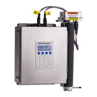
SpectraSensors SS2000 Operator's Manual (80 pages)
Gas Analyzer, H2S in Natural Gas U.S.
Brand:
SpectraSensors
| Category:
Measuring Instruments
| Size: 5 MB
Table of Contents
Table of Contents
5
List of Figures
7
List of Tables
9
1 : Introduction
11
How to Use this Manual
11
Who Should Read this Manual
11
Special Symbols Used in this Manual
12
General Warnings and Cautions
12
Spectrasensors Overview
13
About the Gas Analyzer
14
How the Analyzer Works
14
Figure 1–1: Schematic of a Typical Laser Diode Absorption Spectrometer
15
Figure 1–2: Typical Raw Signal from a Laser Diode Absorption Spectrometer with and Without Mirror Contamination
16
Spectrometer
17
2 : Installation
19
Inspecting the Analyzer and Sample Conditioning System
19
Installing the Analyzer and Sample Conditioning System
19
What Should be Included in the Shipping Box
19
Hardware and Tools for Installation
20
Hardware
20
Tools
20
Connecting Electrical Power to the Analyzer
21
To Connect Electrical Power to the Analyzer
22
Figure 2–1: AC Connection Terminal Block in Control Box
23
Mounting the Analyzer
21
To Mount the Analyzer
21
Connecting Electrical Power to the Optional Enclosure Heater
24
To Connect Electrical Power to the Optional Enclosure Heater
24
Figure 2–3: AC Connection Terminal Block for Optional Enclosure Heater
25
Connecting Electrical Power to an Analyzer with an Optional Type X Purge
26
Figure 2–4: Type X Enclosure Purge Wiring
27
Connecting the Input and Output Signals
28
To Connect the Signal Cables
28
Figure 2–5: Mating Terminal Block for Connecting Signal Cables
29
Connecting the Gas Lines
30
To Connect the Sample Inlet Line
31
To Connect the Sample Return Line
32
Connecting the Optional Automatic Validation Gas (if Applicable)
32
To Connect the Validation Source
32
To Connect the Optional Purge System
33
Conditioning the Analyzer Tubing
34
3 : Operating the SS2000 System
35
Powering up the Analyzer
35
To Power up the Analyzer
35
Powering down the Analyzer
36
To Power down the Analyzer
36
Operating the Analyzer from the Keypad
37
Modes and Functions Defined
38
Mode 1: (Normal Mode)
38
Mode 2: (Set Parameter Mode)
39
Mode 3: Not Used
39
To Change Parameters in Mode 2
39
Spectrum Average
39
High Alarm Action
40
Logger Rate
41
Pressure Unit
41
Temperature Unit
41
Cancel Scrub Alarm
42
Concentration Unit
42
Peak Tracking
42
4 /20 Alarm Option
43
Cancel General Alarm
43
Mode 4: (System Diagnostic Parameters - Channel A)
43
Mode 5: (System Diagnostic Parameters - Channel B)
44
Mode 6: (Diagnostic Data Download)
44
Scaling and Calibrating the Current Loop Signal
44
To Scale the Current Loop Signal
44
Figure 3–4: Temperature and Pressure Sensor Cable Connection
45
Alarms
46
Receiving Serial Data (RS-232 Output)
47
To Launch Hyperterminal
47
Figure 3–5: Connection Description Window
48
Figure 3–7: COM Properties Window
49
To Capture and Save Data from the Serial Port
50
To Read Diagnostic Data with Hyperterminal
50
Viewing Diagnostic Data with Microsoft Excel
51
To Import the Data File into Excel
51
Figure 3–9: Sample Diagnostic Data Output
52
Figure 3–10: Opening a Data File in Excel
53
Validating the Analyzer
54
Calibrating the Analyzer
55
Figure 3–14: Chart Wizard - Step 1 Window
56
Figure 3–16: Format Data Series Window
57
About the Sample Conditioning System
59
Operating the Sample Conditioning System
59
Servicing the Scrubber
62
To Replace the Scrubber and Scrubber Indicator
63
Appendix A: Troubleshooting
65
Contamination
65
To Keep the Sampling Lines Clean
65
Gas Leaks
65
Cleaning the Mirrors
66
Tools and Supplies
66
To Clean the Mirrors
66
Electrical Noise
67
Excessive Sampling Gas Temperatures and Pressures
67
Instrument Problems
68
Service Contact
71
Disclaimers
72
Warranty
72
Appendix B: Specifications
73
Physical Specifications
73
Index
77
Advertisement
Related Products
SpectraSensors SS2100
Spectrasensors SS2100i-1
SpectraSensors SS500
SpectraSensors SS3000
SpectraSensors SS1000
Spectrasensors 2000 Series
SpectraSensors Categories
Measuring Instruments
Analytical Instruments
More SpectraSensors Manuals
Login
Sign In
OR
Sign in with Facebook
Sign in with Google
Upload manual
Upload from disk
Upload from URL