Table of Contents
Advertisement
Quick Links
Advertisement
Table of Contents

Related Manuals for Spectrasensors SS2000


Summary of Contents for Spectrasensors SS2000
- Page 1 SS2000 Gas Analyzer Operator’s Manual S in Natural Gas (U.S.)
- Page 3 Fax: 909.948.4100 www.spectrasensors.com Copyright © 2007 SpectraSensors, Inc. No part of this manual may be reproduced in whole or in part without the express written permission of SpectraSensors, Inc. SpectraSensors reserves the right to change product design and specifications at any...
- Page 4 THIS PAGE INTENTIONALLY LEFT BLANK...
-
Page 5: Table Of Contents
SpectraSensors Overview ........ - Page 6 Pressure Unit ......... . . 3–7 Concentration Unit .
-
Page 7: List Of Figures
Figure 2–4: Type X enclosure purge wiring. 2–9 Figure 2–5: Mating terminal block for connecting signal cables. 2–11 Figure 2–6: SS2000 electronics control board showing signal terminal block and alarm relays. 2–13 Figure 3–1: SS2000 LCD display. 3–2 Figure 3–2: SS2000/3000 Keypad. - Page 8 THIS PAGE INTENTIONALLY LEFT BLANK S in Natural Gas...
-
Page 9: List Of Tables
IST OF ABLES Table 2–1: Output/Input signal connections. 2–12 Table 3–1: Typical values for parameter setpoints. 3–6 Table A–1: Potential instrument problems and their solutions. A–4 Table B-1: SS2000 H S in Natural Gas Analyzer Specifications. B–1 SS2000 Operator’s Manual... - Page 10 THIS PAGE INTENTIONALLY LEFT BLANK S in Natural Gas...
-
Page 11: Who Should Read This Manual
Take a moment to familiarize yourself with this Operator’s Manual by reading the Table of Contents. Because there are many options and accessories available for the SS2000, this manual has been assembled in a modular fashion with sections addressing the specific options and accessories ordered with this particular unit. -
Page 12: Special Symbols Used In This Manual
Introduction Special Symbols Used in This Manual This manual uses the following symbols to represent potential hazards, caution alerts, and important information associated with the analyzer. Every symbol has significant meaning that should be heeded. This icon denotes a warning statement. Warning statements indicate a potentially hazardous situation, which, if not avoided, may result in serious injury or death. -
Page 13: Spectrasensors Overview
Function, sizing, proper installation, operation, and maintenance are beyond the control of SpectraSensors and are the responsibilities of the system designer and user. If equipment is used in a manner not specified by the manufacturer, the protection provided by the manufacturer may be impaired. -
Page 14: About The Gas Analyzer
With the SS2000 analyzer, sample gas flows continuously through the sample cell ensuring that the sample is always representative of the flow in the main pipe. -
Page 15: Figure 1–1: Schematic Of A Typical Laser Diode Absorption Spectrometer
SS2000 Operator’s Manual GAS OUT MIRROR MIRROR DETECTOR I(λ) LASER (λ) TRACE GAS ABSORPTION α(λ) GAS IN Figure 1–1 Schematic of a typical laser diode absorption spectrometer. Due to their inherent structure, the molecules in the sample gas each have characteristic natural frequencies (or resonances). -
Page 16: Figure 1–2: Typical Raw Signal From A Laser Diode Absorption Spectrometer With And Without Mirror Contamination
(ppb) detection levels are possible (depending on target and background species) at real-time response rates (on the order of 1 second). All SpectraSensors TDL gas analyzers employ the same design and hardware platform. Measuring different trace gases such as H... -
Page 17: Spectrometer
SS2000 Operator’s Manual Figure 1–3 Typical normalized absorption signal from a laser diode absorption spectrometer. Figure 1–4 Typical normalized 2 signal where the species concentration is proportional to the peak height. – S in Natural Gas... - Page 18 SpectraSensors TDL analyzers the highest reliability and lowest total cost of ownership gas analyzer platform. –...
-
Page 19: What Should Be Included In The Shipping Box
NSTALLATION This section describes the processes used to initially install and configure your SS2000. Once the analyzer arrives, you should take a few minutes to examine the contents before installing the unit. This section discusses: What Should be Included in the Shipping Box •... -
Page 20: Hardware And Tools For Installation
Pressure regulator (if not included) • 1/2” Unistrut (or equivalent) bolts and spring nuts ® • Stainless steel tubing (SpectraSensors recommends using 1/4” O.D. • x .035” wall thickness, welded or seamless stainless steel tubing) 1/2” conduit hubs • Conduit •... -
Page 21: Mounting The Analyzer
SS2000 Operator’s Manual Mounting the Analyzer The SS2000 analyzer is manufactured for wall or Unistrut (or equivalent) metal framing installations. Depending on your application and configuration, the analyzer will come mounted on a plate or Unistrut frame. Refer to the layout diagrams in Appendix B for detailed mounting dimensions. -
Page 22: To Connect Electrical Power To The Analyzer
Installation requirements. All work must be performed by technicians qualified in electrical conduit installation. Before attaching the wiring to the analyzer, make sure all power to the wires is off. Careful consideration should be taken when grounding. Properly ground the unit by connecting ground leads to the grounding studs provided throughout the system that are labeled with the ground symbol Depending on your configuration, the electrical wiring can typically be... -
Page 23: Figure 2–1: Ac Connection Terminal Block In Control Box
SS2000 Operator’s Manual An approved switch or circuit-breaker rated for 15 amps should be used and clearly marked as the disconnecting device for the analyzer. 3. For AC systems, pull ground, neutral and hot wires into the control box. For DC systems, pull ground, plus and minus wires. -
Page 24: Connecting Electrical Power To The Optional Enclosure Heater
Installation VALVE & VALVE & ALARM ALARM RELAYS RELAYS (if applicable) (if applicable) Figure 2–2 DC connection terminal block in control box. Connecting Electrical Power to the Optional Enclosure Heater Units with an optional enclosure heater will have an additional power connection through a conduit hub located at the bottom right of the enclosure. -
Page 25: Figure 2–3: Ac Connection Terminal Block For Optional Enclosure Heater
SS2000 Operator’s Manual 3. Run conduit from the power source panel to the conduit hub on the lower right side of the heated enclosure. Because the breaker or switch in the power panel will be the primary means of disconnecting the power from the heater, the... -
Page 26: Connecting Electrical Power To An Analyzer With An Optional Type X Purge
Installation 7. Connect the ground wire to the ground terminal marked Connecting Electrical Power to an Analyzer with an Optional Type X Purge Units with an optional Type X purge require two power connections via a 3/4” NPT hole on the purge controls. The purge system’s Electronic Power Control Unit (EPCU) module assembly MUST be removed, exactly as described below, prior to conduit, wire or wiring harness installation. -
Page 27: Figure 2–4: Type X Enclosure Purge Wiring
SS2000 Operator’s Manual An approved switch or circuit-breaker rated for 15 amps should be used and clearly marked as the disconnecting device for the analyzer. ENCLOSURE PROTECTION BONDING JUMPER VENT EPV SENSOR ISOLATED GROUND TERMINATIONS MODULE RAPID ISB MODULE TERMINATIONS ®... -
Page 28: Connecting The Input And Output Signals
Installation 14. Reinstall the modular plug-in terminals to their corresponding sockets on the EPCU base module, by folding the wires over gently and pushing the fold of wire down and away from the base module, into the bottom wiring cavity located between the conduit openings. 15. -
Page 29: Figure 2–5: Mating Terminal Block For Connecting Signal Cables
Figure 2–5 Mating terminal block for connecting signal cables. 3. Pull the customer-supplied cable for the current loop, the SpectraSensors external serial cable (included in the shipping box), and up to five optional digital inputs/outputs through the conduit into the control box. -
Page 30: Connecting The Gas Lines
Appendix B for guidance. All work must be performed by technicians qualified in pneumatic tubing. SpectraSensors recommends using 1/4” O.D x .035” wall thickness, welded or seamless stainless steel tubing. Refer to the system layout drawing in Figure B–1 on page B–2 for inlet and outlet port locations. -
Page 31: To Connect The Sample Inlet Line
VAL. #1 ACTIVE GENERAL ALARM OPTIONAL VALIDATION FAIL ALARM Figure 2–6 SS2000 electronics control board showing signal terminal block and alarm relays. To connect the sample inlet line: 1. Determine appropriate tubing route from the sample source to the the analyzer. -
Page 32: To Connect The Sample Return Line
4. Tighten all fittings to fitting manufacturer’s specifications. Secure tubing to appropriate structural supports as required. 5. Check all connections for gas leaks. SpectraSensors recommends using a liquid leak detector. Do not exceed 10 psig (0.8 barg) in sample cell. Damage to cell window may result. -
Page 33: To Connect The Optional Purge System
4. Tighten all fittings to fitting manufacturer’s specifications. Secure tubing to appropriate structural supports as required. 5. Check all connections for gas leaks. SpectraSensors recommends using a liquid leak detector. Connecting the Optional Purge (If Applicable) -
Page 34: Conditioning The Analyzer Tubing
NPT fitting. 6. Tighten all fittings to fitting manufacturer’s specifications. Secure tubing to appropriate structural supports as required. 7. Check all connections for gas leaks. SpectraSensors recommends using a liquid leak detector. Conditioning the Analyzer Tubing... -
Page 35: 3: Operating The Ss2000 System
See Figure 2–1 for locating fuses. If you need to replace a fuse, use only the same type and rating of fuse as the original. To Power up the Analyzer: 1. Power up the analyzer by energizing the circuit to the analyzer. – SS2000 Operator’s Manual... -
Page 36: Powering Down The Analyzer
Operating the SS2000 System 2. The system goes through an initialization period, then the LCD displays the Normal Mode screen. <NORMAL MODE> 3. Three to four minutes are required for the analyzer to establish reference spectra before displaying a reading. -
Page 37: Operating The Analyzer From The Keypad
The SpectraSensors keypad is shown in Figure 3–2. To activate any functions on the keypad, press the mode key # followed by a number on the keypad to specify a mode. -
Page 38: Modes And Functions Defined
P — Pressure in the sample cell in units selected in Mode 2. • T — Temperature in the sample cell in units selected in Mode 2. • <NORMAL MODE> H2S: 50 ppmv P: 14.7PSI T: 76.1F Figure 3–3 SS2000 measurement display. – S in Natural Gas... -
Page 39: Mode 2: (Set Parameter Mode)
SS2000 Operator’s Manual Mode 2: (Set Parameter Mode) Enables user to view and change Channel A measurement parameters. Press the # key followed by the 2 key. The LCD prompts for a numeric password. <SET PARAMETER MODE> # Spectrum Average... -
Page 40: High Alarm Action
Operating the SS2000 System Table 3–1 Typical values for parameter setpoints. Parameter Setting Function Spectrum Average 1 - 100 Sets the number of Default = 64 scans averaged for each display reading High Alarm Action 0 or >0 - Full Scale... -
Page 41: Logger Rate
SS2000 Operator’s Manual Logger Rate <SET PARAMETER MODE> Logger Rate (s) Enter a Value For applications where an external data logger is employed, use the logging rate to set the averaging period used by the analyzer. The display and the current loop output will each have a value representing the average of the concentration over the last time interval equal to Logger Rate. -
Page 42: Concentration Unit
Operating the SS2000 System Concentration Unit <SET PARAMETER MODE> Concentration Unit 0:ppmv 1:lb/mmscf The Concentration Unit parameter designates the display units for the measured concentration. There are two choices: 0 for ppmv and 1 for lb/mmscf. Press the value corresponding to the desired units followed by the * key to enter the value and cycle to the next parameter. -
Page 43: 4/20 Alarm Option
SS2000 Operator’s Manual 4/20 Alarm Option <SET PARAMETER MODE> 4/20 Alarm Option 0-No, 1-High, 2-Low The 4/20 Alarm Option determines the current loop state upon an alarm condition. Enter 0 for no action, 1 for the current loop to assume a high state... -
Page 44: Mode 5: (System Diagnostic Parameters - Channel B)
Operating the SS2000 System DryPressure: Shows the pressure in the measurement cell when • scrubbed sample gas is flowing through it. WetTemp: Shows the temperature in the measurement cell when • normal sample gas is flowing through it. WetPressure: Shows the pressure in the measurement cell when •... -
Page 45: Figure 3–4: Temperature And Pressure Sensor Cable Connection
SS2000 Operator’s Manual 2. Switch off the power to the analyzer using the switch or circuit- breaker designated as the disconnection device for the equipment. 3. Disconnect the small in-line circular temperature/pressure connector on the cable coming from the sample cell, as shown in Figure 3–4. -
Page 46: Alarms
Operating the SS2000 System Option, enter Mode 2 by pressing the # key followed by the 2 key. When prompted for a password, press 3142 followed by the * key to enter the number. 8. Press the * key multiple times to scroll through the parameters until 4/20 Alarm Option displays. -
Page 47: Receiving Serial Data (Rs-232 Output)
SS2000 Operator’s Manual Laser Power too High: this fault occurs when the DC signal is • saturated typically as a result of the absence of absorbing gas in the measurement cell. Pressure too High: this fault occurs when the pressure in the •... -
Page 48: Figure 3–5: Connection Description Window
Operating the SS2000 System 7. The Connect To window appears prompting for a connection, as shown in Figure 3–6. Click the Menu Arrow under Connect Using to view the choices. Figure 3–5 Connection Description window. Figure 3–6 Connect To window. -
Page 49: Figure 3–7: Com Properties Window
SS2000 Operator’s Manual Figure 3–7 COM Properties window. 9. Once the port is chosen, the COM Properties window appears. Make sure the COM properties for the port selected reflect those shown in Figure 3–7 (19200 baud, 8 data bits, 1 stop bit, no parity, and no flow control). -
Page 50: To Capture And Save Data From The Serial Port
Operating the SS2000 System Wet Temperature (C) - the measured operating temperature in the • spectrometer cell Wet Pressure (mbar) - the measured operating pressure in the • spectrometer cell The number of seconds between each line of data output should be the Spectrum Average number set in Mode 2 divided by 4. -
Page 51: Viewing Diagnostic Data With Microsoft Excel
SS2000 Operator’s Manual 2. To save the data from the serial port, use the Transfer/Capture Text function and enter the Filename to where you would like to store the captured data. 3. Once capturing is in place, enter Mode 6 by pressing # key followed by the 6 key. -
Page 52: Figure 3–9: Sample Diagnostic Data Output
Operating the SS2000 System Operating Parameters: phase: 340.000000, MidPoint: 55.000000, Ramp: 40.000000, IMod: 20.000000, Max Concentration: 300, Min Concentration: SpectraAverage: Alarm: LogRate: Temperature Unit: Pressure Unit: Concentration unit: ppmv PeakTracking: Spectrum Data: Temperature through Scrubber: 39.731316C, Pressure through Scrubber: 975.562927mb, Temperature by-pass Scrubber: 39.947807C,... -
Page 53: Figure 3–10: Opening A Data File In Excel
SS2000 Operator’s Manual Figure 3–10 Opening a data file in Excel. Figure 3–11 Setting data type in Text Import Wizard. 3. Under Delimiters, choose the Tab and Space options, check the Treat Consecutive Delimiters as One box, as shown in Figure –... -
Page 54: Validating The Analyzer
Operating the SS2000 System 3–12, and then click Finish to display the spreadsheet. The first few Figure 3–12 Setting Tab and Space as delimiters. lines look like the normal serial output data received before the Mode 6 command was entered. Look for the three columns of numbers at the bottom of the file. -
Page 55: Calibrating The Analyzer
LCD settles. SpectraSensors recommends validating the analyzer using only H S in methane. A bottle of test gas with a certified concentration representing 50% of full scale should be used. -
Page 56: Figure 3–14: Chart Wizard - Step 1 Window
Operating the SS2000 System Figure 3–14 Chart Wizard - Step 1 window. 3000 2500 2000 1500 Series1 Series2 1000 -100 600 -150 -500 Figure 3–15 Data file plot in Excel. – S in Natural Gas... -
Page 57: Figure 3–16: Format Data Series Window
SS2000 Operator’s Manual Figure 3–16 Format Data Series window. – S in Natural Gas... - Page 58 Operating the SS2000 System THIS PAGE INTENTIONALLY LEFT BLANK – S in Natural Gas...
-
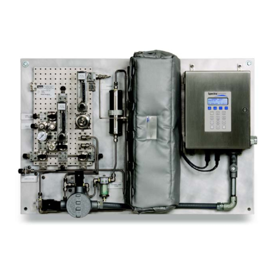
Page 59: About The Sample Conditioning System
YSTEM ATURAL About the Sample Conditioning System The SS2000 analyzer for measuring H S in natural gas comes equipped with an integral sample conditioning system, as illustrated by the flow schematic in Figures 4–1 and 4–2. Because of the important role the sample conditioning system plays in the analysis, care should be taken to install and maintain the system in order to ensure optimum performance. - Page 60 Gas Sample Conditioning System - H S in Natural Gas – S in Natural Gas...
- Page 61 SS2000 Operator’s Manual – S in Natural Gas...
-
Page 62: Servicing The Scrubber
Gas Sample Conditioning System - H S in Natural Gas SCRUBBER SCRUBBER INDICATOR Figure 4–3 Scrubber and scrubber indicator. However, regular checks of the specified values via the pressure gauges and flow meters on the system is recommended. Servicing the Scrubber The H S scrubber contains material that gradually loses its scrubbing ability with use. -
Page 63: To Replace The Scrubber And Scrubber Indicator
SS2000 Operator’s Manual Figure 4–4 Scrubber indicator showing H breakthrough. To Replace the Scrubber and Scrubber Indicator: 1. Turn off the sample inlet valve. 2. Connect a nitrogen purge line to the sample inlet port making sure not to exceed the maximum sample inlet pressure specification shown on the schematic in Figure 4–1.Make sure there is a check... - Page 64 Gas Sample Conditioning System - H S in Natural Gas 10. Reopen the sample inlet valve and check for leaks. – S in Natural Gas...
-
Page 65: Appendix A: Troubleshooting
4. Wash the sampling line with alcohol or acetone and blow dry with mild pressure from a dry air or nitrogen source. It may be necessary to heat the lines for a few minutes to clear residual solvent from the lines. – SS2000 Operator’s Manual... -
Page 66: Cleaning The Mirrors
Troubleshooting 5. Reconnect the gas sampling line to the inlet port of the analyzer and check for leaks. The sample cell assembly contains a low-power, 10 mW MAX, CW Class 3IIIb invisible laser with a wavelength between 800- 3000 nm. Never open the sample cell flanges or the optical assembly unless the power is turned off. -
Page 67: Excessive Sampling Gas Temperatures And Pressures
SS2000 Operator’s Manual Never rub an optical surface, especially with dry tissues, as this can mar or scratch the coated surface. 3. Remove dust and other large particles of debris using a bulb blower or dry compressed air/nitrogen. Pressurized gas duster products are not recommended as the propellent may deposit liquid droplets onto the optic surface. -
Page 68: Instrument Problems
Perhaps the existing tubing needs to be replaced with stainless steel flexible tubing. Press # 6 to capture diagnostic data and send the file to SpectraSensors. Possible alignment problem. Contact a factory sales representative for service information. Possible mirror contamination issue. - Page 69 SS2000 Operator’s Manual Table A–1 Potential instrument problems and their solutions. Pressure too Low Pressure too Check that the actual pressure in the measurement cell is within specification High fault (Table B-1 on page B–1). If the pressure reading is incorrect,...
- Page 70 Return to factory for service. Reading seems to always be high by a Capture diagnostic data and send the fixed amount file to SpectraSensors. See “To read diagnostic data with HyperTermi- nal:” on page 3-16. Reading seems to always be high by a...
-
Page 71: Service Contact
Check for contamination in the sample system, especially if the readings are much higher than expected. Capture diagnostic data and send the file to SpectraSensors. See “To read diagnostic data with HyperTermi- nal:” on page 3-16. Reading goes to “0”... -
Page 72: Disclaimers
Troubleshooting Disclaimers SpectraSensors accepts no responsibility for consequential damages arising from the use of this equipment. Liability is limited to replacement and/or repair of defective components. This manual contains information protected by copyright. No part of this guide may be photocopied or reproduced in any form without prior written consent from SpectraSensors. -
Page 73: Appendix B: Specifications
Appendix B: Specifications Table B-1 SS2000 H S in Natural Gas Analyzer Specifications. Performance Concentration (H 0–20 ppmv Display updates every 16 seconds Response Time (software adjustable) Repeatability ±0.5 ppmv Application Data Environmental Temperature Range –4 °F to 122 °F (–20 °C to 50 °C) Environmental Relative Humidity 80% for temperatures up to 31 °C max... - Page 74 Specifications – S in Natural Gas...
- Page 75 SS2000 Operator’s Manual – S in Natural Gas...
- Page 76 Specifications – S in Natural Gas...
-
Page 77: Index
NDEX 4-20 mA current loop 2–10, 3–10 Calibrating 3–10 Absorption 1–4, 1–5 Receiver 2–12 Absorption coefficient 1–5 Current loop receiver 3–12 Absorption profile 1–5 Current tuning 1–5 Absorption spectrometer 1–4 Data 1–5 Absorption spectroscopy 1–4 Diagnostic 3–9, 3–10, 3–18 Accessories. See Options. Normalized 2f 1–7 Acetone A–1, A–2, A–3 Normalized absorption 1–7... - Page 78 Hardware 2–2 Null 3–16 Hazardous environments 1–4 Operating the sample conditioning sys- Heated enclosure 1–4 tem 4–1 HyperTerminal 3–13 Operating the SS2000/SS3000 system Import stored data into spreadsheet 3–1 3–17 Optional analyzer hood 2–3 Incident energy 1–5 Optional automatic validation 2–14 Initialization period 3–2...
- Page 79 Index Peak tracking function 3–8 2–15 Pin numbers 2–11 Symbols 1–2 Port System conditioning 2–16 Bypass 4–1 Temperature 3–3 Bypass return 2–14 Temperature connector 3–11 Inlet 4–1 Tools 2–2 Nitrogen purge 4–5 Tools and supplies A–2 Nitrogen purgert 4–5 Trace species detection 1–4 Pressure relief vent 2–14 Tunable diode laser 1–4 Purge system inlet 2–15...
- Page 80 THIS PAGE INTENTIONALLY LEFT BLANK...
Need help?
Do you have a question about the SS2000 and is the answer not in the manual?
Questions and answers