Table of Contents
Advertisement
Quick Links
Products
Solutions
Services
4900002260 Rev C
Safety Manual
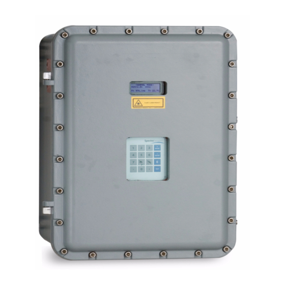
SS2100i-1 TDL Gas Analyzer
ATEX/IECEx: Zone 1
Copyright © 2020 SpectraSensors, Inc. No part of this manual may be reproduced in
whole or in part without the express written permission of SpectraSensors, Inc.
SpectraSensors reserves the right to change product design and specifications at any
time without prior notice.
Advertisement
Table of Contents

Related Manuals for Spectrasensors SS2100i-1


Summary of Contents for Spectrasensors SS2100i-1
- Page 1 SS2100i-1 TDL Gas Analyzer ATEX/IECEx: Zone 1 Copyright © 2020 SpectraSensors, Inc. No part of this manual may be reproduced in whole or in part without the express written permission of SpectraSensors, Inc. SpectraSensors reserves the right to change product design and specifications at any...
-
Page 3: Table Of Contents
SpectraSensors Overview ........ - Page 4 SS2100i-1 Analyzer Potentially Hazardous Substances ........5-8 Disposal of hazardous substances .
- Page 5 TABLES Table 2-1. SS2100i-1 analyzer specifications ......2-4 Table 3–1. Inspection Schedule for Ex “d”, Ex “e”, Ex “n”....3-7 Table 4–1.
- Page 6 SS2100i-1 Analyzer THIS PAGE INTENTIONALLY LEFT BLANK 4900002260 rev. C 12-9-20...
-
Page 7: Intended Equipment Use
The information provided should be read and referenced by anyone installing, operating or having direct contact with the SS2100i-1 analyzer. Any use of the equipment in a manner not specified by SpectraSensors could impair the protection provided by the equipment. -
Page 8: Documents Provided With The Ss2100I-1 Analyzer
SS2100i-1 Analyzer Documents Provided with the SS2100i-1 Analyzer Each SS2100i-1 analyzer shipped from the factory is packaged with documents specific to the model that was purchased. At a minimum, the documents included with each shipment are: • Safety Manual •... -
Page 9: 2: General Safety Information
NFORMATION General Warnings and Cautions Instructional icons are provided in this manual and on the SS2100i-1 unit to alert the user of potential hazards, important information and valuable tips. Following are the symbols and associated warning and caution types to observe when servicing the analyzer. -
Page 10: Equipment Labels
SS2100i-1 Analyzer Technicians are expected to follow all safety protocols established by the customer that are necessary for servicing or operating the analyzer. This may include, but is not limited to, lockout/tag-out procedures, toxic gas monitoring protocols, personal protective equipment (PPE) requirements, hot work permits and other... -
Page 11: Instructional Symbols
Maximum voltage and current specifications for fuses. Analyzer Technical Specification Refer to “Equipment rating” on page 2-4 for specifications related to the SS2100i-1 analyzer. Peripheral devices For systems equipped with peripheral devices, e.g., probe assemblies, sample conditioning system and heated sample transport lines, refer to the documentation provided by the manufacturer for instruction on installation, operation, etc. -
Page 12: Equipment Rating
SS2100i-1 Analyzer Equipment rating The following equipment rating information is provided for the SS2100i-1 Table 2-1 below. This information includes, but is not limited to, the following: • Voltage and power rating • Description of all input and output connections •... - Page 13 General Safety Information Table 2-1 SS2100i-1 Analyzer Specifications (Continued) Electrical & Communications (Continued) Digital Signals Outputs: (5); Hi/Lo Alarm, General Fault, Validation Fail , Validation 1 Active , Validation 2 Active Inputs: (2); Flow Alarm , Validation Request Protocol Modbus Gould RTU, Daniel RTU or ASCII...
-
Page 14: Potential Risks Affecting Personnel
SS2100i-1 Analyzer Potential Risks Affecting Personnel Technicians are expected to follow all safety protocols established by the customer that are necessary for servicing the analyzer. This may include, but is not limited to, lockout/tagout procedures, toxic gas monitoring protocols, PPE requirements, hot work... -
Page 15: Mitigating Risks
General Safety Information Mitigating risks Technicians are expected to follow all safety protocols established by the customer that are necessary for servicing the analyzer. This may include, but is not limited to, lockout/tagout procedures, toxic gas monitoring protocols, PPE requirements, hot work permits and other precautions that address safety concerns related to performing service on process equipment located in hazardous areas. -
Page 16: Explosion Hazard
SS2100i-1 Analyzer If service must be performed with power engaged (gain adjustment, etc.): 1. Note any live electrical components and avoid any contact with them. 2. Only use tools with a safety rating for protection against accidental contact with voltage up to 1000 V (IEC 900, ASTF-F1505-04, VDE 0682/201). -
Page 17: Hardware And Tools For Installation
Hardware • Mounting hardware Mounting hardware used for wall-mounting the SS2100i-1 must be able to support four times the weight of the instrument (86 kg [190 lbs]) not including the sample conditioning system). • Stainless steel tubing (SpectraSensors recommends using 1/4” O.D. -
Page 18: Lifting/Carrying The Analyzer
The SS2100i-1 is intended to be mounted to a wall or secured upright frame. Secure the analyzer frame in position using bolts or screws of the size indicated in the drawings included in the Hardware Manual provided with the analyzer. -
Page 19: Protective And Chassis Ground Connections
2. Connect the system ground to the ground bus bar as shown in Figure 5–2 on page 5–2 during the electrical power connection. Refer to the SS2100i-1 Hardware Manual (P/N 4900002224) for instruction. Electrical Wiring Requirements Interconnection of the analyzer enclosure and cell enclosure shall... -
Page 20: Cable Installation
SS2100i-1 Analyzer The external circuit breaker must be provided by the customer as part of the equipment installation and shall meet the relevant requirements of IEC 60947-1 and IEC. This switch or breaker must be suitably located and easily reached (within 3 meters). -
Page 21: Cable Glands
(5) full threads. Suitable grease may be used as long as it is non-setting, non-metallic and non-combustible and any earthing between the device and the flameproof enclosure is maintained. SpectraSensors recommends using STL8 screw thread lubricant or equivalent on all screw thread and its taped opening. -
Page 22: Inspecting The Analyzer
There are three grades of inspection; visual, close and detailed. Visual and close inspections can be performed with the analyzer energized. Detailed inspections generally require the equipment to be isolated. SpectraSensors recommends, at a minimum, a visual inspection to be performed after installation to reinforce understanding that the product is installed to manufacturer specifications and to the appropriate standards. -
Page 23: Table 3-1 Inspection Schedule For Ex "D", Ex "E", Ex "N
Equipment Installation Bolts, screws and similar parts, depending on the type of protection required, shall only be replaced by similar parts in accordance with the manufacturer’s design. Refer to Table 3–1 below for the inspection schedule for Ex “d”, Ex “e”, Ex “n” equipment. - Page 24 SS2100i-1 Analyzer Table 3–1 Inspection Schedule for Ex “d”, Ex “e”, Ex “n” (Continued) Items to Description Ex “d” Ex “e” Ex “n” Check General (All Equipment) Grade of Inspection Encapsulated components are undamaged Breathing and draining devices are satisfactory...
-
Page 25: 4: Equipment Operation
QUIPMENT PERATION Firmware Version Each SpectraSensors analyzer operates based on its own version of firmware. The firmware version for each analyzer is listed in the system calibration report, and displays upon start-up of the analyzer. Detailed operational instructions are provided in the Firmware Manual shipped with the purchased analyzer. Manuals can also be found on the SpectraSensors website (www.spectrasensors.com) -
Page 26: Exd Accessory Conditions Of Use
SS2100i-1 Analyzer 7. Allow all residual gas to dissipate from the lines. 8. Close any valves controlling the sample flow effluent to the low pressure flare or atmospheric vent. 9. Disconnect power to the system. 10. Disconnect all tubing and signal connections. - Page 27 Equipment Operation Table 4-2 Exd accessory conditions of use (Continued) Accessory Rating Notes Type Breather/drainer Exd, Zone 1 3. Breather/drainer specified shall meet the (Continued) following requirements: • Exd enclosures with an internal volume 75 L 175 L. •...
- Page 28 SS2100i-1 Analyzer THIS PAGE INTENTIONALLY LEFT BLANK. – 4900002260 rev. C 12-9-20...
-
Page 29: Figure 5-1 Analyzer Component Overview
5 - E QUIPMENT AINTENANCE AND ERVICE The SS2100i-1 analyzer supports two levels inside the analyzer enclosure. The top level contains the electronics assembly, and the bottom level is the measurement cell assembly. Refer to Figure 5–1 below. ELECTRONICS PANEL... -
Page 30: Figure 5-2 Components On Electronics Panel Assembly (Upper Level)
SS2100i-1 analyzer 4-20 mA AO 4-20 mA AI BOARD BOARD FUSE (F3) TEMPERATURE CONTROL BOARD ANALYZER POWER SUPPLY HIGH TEMPERATURE LIMIT ARM9 CONTROL THERMOSTAT ELECTRONICS SET AT 70 C RELAYS RS-232 TO RS-485 CONVERTER AC LINE FILTER AUXILIARY POWER SUPPLY... -
Page 31: 5: Equipment Maintenance And Service
Equipment Maintenance and Service TRANSITION PLATE THERMISTOR HEATER THERMISTOR ASSEMBLY MEASUREMENT CELL TEMPERATURE CONTROLLER AC TERMINAL BLOCK FOR HEATER SOLID-STATE PRESSURE RELAY SENSOR Figure 5–3 Components on sample cell panel assembly (8/28 m sample cell) (Lower level) – Safety Manual... -
Page 32: Figure 5-4. Components On Sample Cell Panel Assembly
SS2100i-1 analyzer TRANSITION PLATE HEATER THERMISTOR PRESSURE SENSOR MEASUREMENT CELL TEMPERATURE CONTROLLER AC TERMINAL THERMISTOR BLOCK FOR ASSEMBLY HEATER SOLID-STATE RELAY Figure 5–4 Components on sample cell panel assembly (0.8 m sample cell) (Lower level) – 4900002260 rev. C 12-9-20... -
Page 33: Figure 5-5. Components On Sample Cell Panel Assembly
Equipment Maintenance and Service TRANSITION PLATE THERMISTOR MEASUREMENT CELL HEATER PRESSURE SENSOR SAMPLE TEMPERATURE THERMISTOR AC TERMINAL BLOCK FOR SOLID HEATER STATE RELAY TEMPERATURE CONTROLLER Figure 5–5 Components on sample cell panel assembly (0.1 m sample cell) (Lower level) – Safety Manual... -
Page 34: Accessing The Measurement Cell
SS2100i-1 analyzer Accessing the Measurement Cell To access the measurement cell for mirror cleaning or to replace the pressure sensor, for example, the electronics assembly (top level) panel must first be removed. Refer to the Hardware Manual for instruction on maintaining the components on the sample cell (lower level) panel. -
Page 35: Figure 5-6 Electronics Assembly Panel
Equipment Maintenance and Service KEYPAD/DISPLAY CABLE CLIPS KEYPAD/ OPTICAL HEAD DISPLAY CABLE CABLE TEMPERATURE/ PRESSURE CABLES WATLOW CONTROLLER QUICK CONNECT WIRE DUCT COVER HEATER POWER TERMINAL PROTECTIVE GROUND Figure 5–6 Electronics assembly panel 10. Gently pull the electronics panel towards you, away from the enclosure, tilting the panel forward slightly to lift up and over the wires connected at the base of the enclosure. -
Page 36: Potentially Hazardous Substances
SS2100i-1 analyzer Figure 5–7 Accessing the measurement cell Potentially Hazardous Substances SS2100i-1 analyzers may be provided with a scrubber and scrubber indicator. See below for proper disposal of these items. Disposal of hazardous substances For analyzer equipped with H S scrubbers, use the following instruction for safe disposal of old components. -
Page 37: Fuse Ratings And Characteristics
Miniature Fuse, 5 x 20 mm, Time Delay 250 VAC/1.2A 1. Housed in fused terminal blocks. Illuminated LED indicates blown fuse. Service Contact For Service, refer to our website for the list of local sales channels in your area (https://www.spectrasensors.com/contact). – Safety Manual... - Page 38 SS2100i-1 analyzer THIS PAGE INTENTIONALLY LEFT BLANK. – 4900002260 rev. C 12-9-20...
- Page 39 4900002260 Rev C www.spectrasensors.com/contact...
Need help?
Do you have a question about the SS2100i-1 and is the answer not in the manual?
Questions and answers