
Related Manuals for Spectrasensors SS2100


Summary of Contents for Spectrasensors SS2100
- Page 1 SS2100 Trace Moisture Analyzer Hardware Installation and Maintenance Manual P/N 4900002257 rev A...
- Page 3 Fax: 713.856.6623 www.spectrasensors.com Copyright © 2017 SpectraSensors, Inc. No part of this manual may be reproduced in whole or in part without the express written permission of SpectraSensors, Inc. SpectraSensors reserves the right to change product design and specifications at any...
-
Page 4: Revision History
Revision History Revision Engineering Order Date EO17089 June 1, 2017... -
Page 5: Table Of Contents
SpectraSensors Overview ........ - Page 6 SS2100 Trace Moisture Analyzer Sample Conditioning System Filters ......3-2 Sample Transport Tubing ........3-2 Sample Bypass Flow Control .
- Page 7 Table of Contents To replace the pressure transducer on a 8-m cell..... B-9 Peak Tracking Reset Procedure ........B-15 Instrument Problems.
- Page 8 SS2100 Trace Moisture Analyzer THIS PAGE INTENTIONALLY LEFT BLANK 4900002257 rev. A 6-1-17...
-
Page 9: List Of Figures
......1-7 Figure 1–5. SS2100 analyzer architecture......1-8 Figure 1–6. - Page 10 Remote mount configuration: Wiring schematic of SS2100 for trace moisture analyzer (solenoids below electronics)..A-11 Figure A–10. Remote mount configuration: Electrical schematic of SS2100 for trace moisture analyzer (solenoids below electronics)..A-12 Figure B–1.
-
Page 11: List Of Tables
Input/output signal connections ......2-13 Table A–1. SS2100 trace moisture analyzer specifications ....A-1 Table A–2. - Page 12 SS2100 Trace Moisture Analyzer THIS PAGE INTENTIONALLY LEFT BLANK viii 4900002257 rev. A 6-1-17...
-
Page 13: Who Should Read This Manual
Pay close attention to this information. General Warnings and Cautions Instructional icons are provided in this manual and on the SS2100 unit to alert the user of potential hazards, important information and valuable tips. Following are the symbols and associated warning and caution types to observe when servicing the analyzer. -
Page 14: Instructional Symbols
SS2100 Trace Moisture Analyzer Failure to follow all directions may result in damage or malfunction of the analyzer. INVISIBLE LASER RADIATION - Avoid exposure to beam. Class 3b Radiation Product. LASER RADIATION Refer servicing to the manufacturer-qualified AVOID EXPOSURE TO BEAM CLASS 3B LASER PRODUCT personnel. -
Page 15: Spectrasensors Overview
A sample conditioning system (SCS) is included with the analyzer. The SCS has been specifically designed to deliver an optimum sample stream that is representative of the process systems stream at the time of sampling. Most SS2100 analyzers are configured for use at extractive natural gas sampling stations. Determining Firmware Version When the analyzer is powered on for the first time, the firmware version will display on the system LCD for approximately seven seconds. - Page 16 With the SS2100 analyzers, sample gas flows continuously through the sample cell ensuring that the sample is always representative of the flow in the main pipe.
- Page 17 Introduction directly proportional to the number of molecules of that particular species in the beam path, or I 1 – ------------- - ------------- - l Figure 1–2 shows the typical raw data from a laser absorption spectrometer scan including the incident laser intensity, I (), and the transmitted intensity, I(), for a clean system and one with contaminated mirrors (shown to illustrate...
-
Page 18: Wavelength Modulation Spectroscopy (Wms) Signal Detection
Wavelength Modulation Spectroscopy (WMS) Signal Detection SpectraSensors takes the fundamental absorption spectroscopy concept a step further by using a sophisticated signal detection technique called wavelength modulation spectroscopy (WMS). When employing WMS, the laser drive current is modulated with a kHz sine wave as the laser is rapidly tuned. -
Page 19: Getting Familiar With The Analyzer
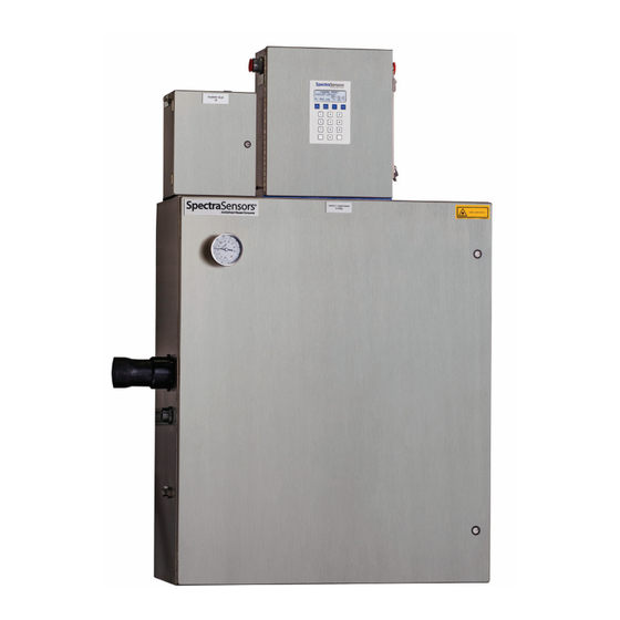
Getting Familiar with the Analyzer Figure 1–5 shows a sample SS2100 analyzer from a front view. The analyzer is typically comprised of two main enclosures; the analyzer electronics and the Sample Conditioning System (SCS). On the front panel of the analyzer electronics, the keypad and LCD display serve as the user interface to the analyzer. - Page 20 SS2100 Trace Moisture Analyzer ANALYZER ELECTRONICS ENCLOSURE KEYPAD, LCD AND OPTIONAL KEYPAD COVER SOLENOID VALVES SAMPLE CONDITIONING SYSTEM (SCS) ENCLOSURE POWER CONNECTIONS SAMPLE SUPPLY SAMPLE RETURN (TO ATMOSPHERE) CHASSIS GROUND Figure 1–5 SS2100 analyzer architecture Power is connected to the analyzer from a 120 VAC, 240 VAC power source or optionally a 24 VDC power source.
- Page 21 FUSES (F2, F1) ALARM/ SIGNAL RELAYS CUSTOMER GROUND TERMINAL BLOCK ASSIGNABLE ALARM COMMON (TB3), INTERNAL PRESSURE TEMPERATURE GENERAL FAULT ALARM Figure 1–6 SS2100 electronics control board (AC) showing signal terminal block and alarm relays – Hardware Installation and Maintenance Manual...
- Page 22 PROTECTIVE GROUND FUSE (F1) ALARM/ SIGNAL RELAYS CUSTOMER TERMINAL GROUND BLOCK (TB3), ASSIGNABLE ALARM COMMON INTERNAL PRESSURE/ GENERAL FAULT TEMPERATURE ALARM Figure 1–7 SS2100 electronics control board (DC) showing signal terminal block and alarm relays – 4900002257 rev. A 6-1-17...
-
Page 23: Table 1-1 Fuse Specifications
Introduction Fuses are located on the electronics control board, as shown in Figure 1–6 and Figure 1–7. If you need to replace a fuse, use only the same type and rating of fuse as the original as listed in Table 1–1. Refer to “Replacing a Fuse”... - Page 24 SS2100 Trace Moisture Analyzer THIS PAGE INTENTIONALLY LEFT BLANK – 4900002257 rev. A 6-1-17...
-
Page 25: What Should Be Included In The Shipping Box
2 - I NSTALLATION This chapter describes the processes used to initially install your SS2100. Once the analyzer arrives, you should take a few minutes to examine the contents of the container before installing the unit. What Should be Included in the Shipping Box The contents of the crates should include: •... -
Page 26: Hardware And Tools For Installation
Mounting hardware (e.g., spring nuts, 3/8” x 1-1/2” machine screws and nuts) Bolts or screws used for wall-mounting the SS2100 must be able to support four times the weight of the instrument (approximately 59 kg [130 lbs] with sample system). -
Page 27: Mounting The Analyzer
Due to the analyzer’s size and weight (configurations can weigh approximately 59 Kg or 130 lbs), SpectraSensors recommends the use of a forklift, pallet jack, etc. to lift and/or move the analyzer. If the analyzer is to be lifted by hand, designate multiple individuals and distribute the weight among personnel to avoid injury. -
Page 28: To Mount The Analyzer
Refer to “Lifting/carrying the analyzer” on page 2-3. SpectraSensors analyzers are designed for operation within the specified ambient temperature range. Intense sun exposure in some areas may cause the analyzer temperature to exceed the maximum. -
Page 29: Connecting Electrical Power To The Analyzer
The electrical power for the SS2100 Trace Moisture analyzer is connected through the conduit hub at the lower right side of the electronics enclosure and the signal wiring is connected through the upper left side of the electronics enclosure. -
Page 30: To Connect Electrical Power To The Analyzer
Refer to Figure 1–5, Figure 1–6 and Figure 1–7 for the protective and chassis ground locations. To connect electrical power to the analyzer: 1. Open the SS2100 analyzer electronics enclosure door. Take care not to disturb the electrical assembly inside. Hazardous voltage and risk of electric shock.Failure to properly ground the analyzer may create a high-voltage shock hazard. -
Page 31: Field Interface Loads (Solenoid Valves)
2–3. 7. Close and tighten the analyzer electronics enclosure door. Field Interface Loads (Solenoid Valves) The SS2100 must be connected to a certified solenoid having a temperature code of T4, T5, or T6 at a maximum ambient temperature of +60 C (+140 –... -
Page 32: Connecting Electrical Power To The Enclosure Heater
SS2100 Trace Moisture Analyzer SOLENOIDS Figure 2–3 DC connection (24 VDC) terminal block in analyzer electronics enclosure Connecting Electrical Power to the Enclosure Heater Units with an enclosure heater will have an additional power connection through a conduit hub located at the bottom right of the SCS enclosure. - Page 33 Installation TERMINAL TERMINAL LINE TERMINAL Figure 2–4 AC connection terminal block for enclosure heater 3. Run conduit from the power distribution panel to the conduit hub on the lower right side of the heated enclosure labeled for power input. Refer to “Application of Conduit Lubricant” on page 2-10. Conduit seals should be used where appropriate in compliance with local regulations.
-
Page 34: Application Of Conduit Lubricant
8. Close the power terminal box and latch the heated enclosure door. Application of Conduit Lubricant To ensure proper installation, SpectraSensors recommends using STL8 lubricant on all conduit screw thread and its taped opening. STL8 Screw Thread Lubricant is a lithium based, anti-galling substance with excellent adhesion that maintains rain-tightness and grounding continuity between conduit fittings. -
Page 35: Connecting The Signals And Alarms
Installation Connecting the Signals and Alarms The 4-20 mA current loop and serial output are connected to a mating terminal block (TB2) located inside the analyzer electronics enclosure (refer to Figure 1–6 and Figure 1–7). By default, the 4-20 mA current loop outputs are factory set to source current. -
Page 36: To Connect The Signal And Alarm Cables
SS2100 Trace Moisture Analyzer To connect the signal and alarm cables: 1. Disconnect power from the analyzer and open the electronics enclosure cover. Take care not to disturb the electrical assembly inside. Hazardous voltage and risk of electric shock. Be sure power to the analyzer is turned off before opening the electronics enclosure and making any connections. -
Page 37: Table 2-1 Input/Output Signal Connections
Installation 5. Connect the 4-20 mA current loop output wires to the appropriate terminals, as indicated in Table 2–1. Table 2–1 Input/output signal connections Terminal Description D-Conn Color Serial RX Pin-3 Black Serial TX Pin-2 COM Serial Ground Pin-5 Shield Current Loop + (Ch. -
Page 38: Changing The 4-20 Ma Current Loop Mode
SS2100 Trace Moisture Analyzer Changing the 4-20 mA Current Loop Mode Changing of the current loop mode may negate specific hazardous area certifications. Contact “Customer Service” on page B-20 for details. By default, the 4-20 mA current loop output is factory set to source current. In some instances it may be necessary to change the 4-20 mA current loop output in the field from source to sink. -
Page 39: Calibrating The Analog Output
Installation 5. Reconnect power to the analyzer. Confirm the 4 mA (min.) and 20 mA (max.) points. 6. Close and tighten the electronics enclosure cover. Refer to the following programming instructions. Calibrating the analog output 1. Connect a calibrator and digital multi-meter into the circuit. 2. -
Page 40: Connecting The Gas Lines
SCS. SpectraSensors recommends using coated 1/4” O.D x 0.035” wall thickness, seamless stainless steel tubing. Refer to Appendix A for supply and return port locations. -
Page 41: To Connect The Sample Returns
Secure tubing to appropriate structural supports as required. 10. Check all connections for gas leaks. SpectraSensors recommends using a liquid leak detector. Do not exceed 10 PSIG (0.7 barg) in sample cell. Damage to cell may result. -
Page 42: To Connect The Bypass Return
Secure tubing to appropriate structural supports as required. 8. Check all connections for gas leaks. SpectraSensors recommends using a liquid leak detector. Do not exceed 10 PSIG (0.7 barg) in sample cell. Damage to cell may result. -
Page 43: Conditioning The Scs Tubing
Secure tubing to appropriate structural supports as required. 8. Check all connections for gas leaks. SpectraSensors recommends using a liquid leak detector. Do not exceed 10 PSIG (0.7 barg) in sample cell. Damage to cell may result. - Page 44 SS2100 Trace Moisture Analyzer THIS PAGE INTENTIONALLY LEFT BLANK – 4900002257 rev. A 6-1-17...
-
Page 45: 3: Sample Conditioning System
Typical SCS Component Overview All SpectraSensors TDL analyzers are designed for extractive sampling rather than in situ applications. This allows for sample conditioning, filtration, temperature, pressure and flow control to protect the optical components of the system, and provides for ease of maintenance without shutting down the process. -
Page 46: Sample Conditioning System Filters
SCS Pressure Regulator All SpectraSensors’ TDL cells are limited to a maximum 10 PSIG pressure. To ensure that this pressure is not exceeded, a pressure regulator is provided inside the sample system. -
Page 47: Sample Dryer
The automatic valves that control switching the sample stream into the dryer or bypassing the dryer are pneumatically operated valves. Validation Systems System validation is accomplished in the SS2100 Trace Moisture analyzer by the use of a permeation device. Refer to “Permeation Validation” on page 4-1. -
Page 48: Checking The Scs Installation
An optional sample probe and/or field pressure reducing station may be provided by SpectraSensors or through a third party. This is not included in a standard configuration. 3. Confirm that the relief valve vent line is properly installed from the field pressure reducing station or the SCS to the low pressure flare or atmospheric connection. -
Page 49: Starting Up The Scs
Sample Conditioning System 8. Confirm that the low pressure flare or atmospheric vent is properly connected, if applicable. 9. Confirm that the analyzer house atmospheric vent is properly installed. 10. Confirm that all sample system tubing has been thoroughly leak checked. -
Page 50: To Start Up The Field Pressure Reducing Station
SS2100 Trace Moisture Analyzer To start up the field pressure reducing station: The process sample at the sample tap may be at a high pressure. Use extreme caution when operating the sample probe isolation valve and field pressure reducing regulator. -
Page 51: To Start Up The Analyzer On Process Sample
Sample Conditioning System Although the exact supply pressure setpoint is not critical, the pressure at the sample system should be within 5 PSIG of the specified supply pressure setpoint. There may be a difference between the pressure readings at the sample tap and inside the SCS due to the pressure drop in the sample transport line under flowing conditions. -
Page 52: To Start Up The Sample System Heater
Firmware Manual for reset instructions. If assistance is still needed, contact SpectraSensors’ Technical Service Group. Refer to “Service Contact” on page B-20. If the SCS enclosure exceeds 149° F (65° C), damage to the system could occur. -
Page 53: To Isolate The Measurement Sample Cell For Short-Term Shutdown
Sample Conditioning System The process sample at the sample tap is at a high pressure. A pressure reducing regulator is located at the sample tap to reduce the sample pressure and enable operation of the SCS at a low pressure. Use extreme caution when operating the sample probe isolation valve and field pressure reducing regulator. -
Page 54: To Isolate The Scs For Short-Term Shutdown
SS2100 Trace Moisture Analyzer To isolate the SCS for short-term shutdown: The SCS can be isolated from the process sample tap for short-term shutdown or maintenance of the SCS without requiring the shutdown of the field pressure reducing station. Process samples may contain hazardous material in potentially flammable and/or toxic concentrations. - Page 55 Sample Conditioning System The process sample at the sample tap may be at a high pressure. A pressure reducing regulator is located at the sample tap to reduce the sample pressure and allow operation of the SCS at a low pressure. Use extreme caution when operating the sample probe isolation valve and field pressure reducing regulator.
-
Page 56: To Purge The Analyzer For Shipment/Relocation
SS2100 Trace Moisture Analyzer To purge the analyzer for shipment/relocation: If the analyzer is configured for differential measurements, purge the system with power “on” to ensure dry and wet portions of SCS are properly purged. 1. Refer to the procedure “To isolate the process sample tap for long-term shutdown”... -
Page 57: Preventive And Demand Scs Maintenance
2. Read and record the flowmeter settings while the gas is flowing. 3. Close the SCS door. Do not leave the SCS door open any longer than absolutely necessary. SpectraSensors recommends no more than 60 seconds. Opening the door may affect the temperature reading until the temperature is stabilized. -
Page 58: To Check Filters
SCS” on page 3-8. 2. Inspect, repair or replace the filter as required. Refer to “Replacing the Filter” on page B-6. For additional information, contact SpectraSensors’ Technical Service Group at 800-619-2861. 3. Restart the system following the procedure in “Starting up the SCS”... -
Page 59: 4: Permeation Validation
Validation Method SpectraSensors uses a permeation validation system to validate low moisture measurements. Permeation validation systems provide a convenient and reliable method of validating the performance of the analyzer, without the need for elaborate blending systems and certified standards that might be impossible to obtain in the field. -
Page 60: Setting The Kp Value
Kp value. Validation of Trace Moisture Measurements Using Permeation Devices For trace moisture systems, SpectraSensors employs a patented G-CAL permeation tube. The permeation device is designed to continuously release a fixed rate of analyte, approximately 2000ng/min at 50 C. - Page 61 Permeation Validation Figure 4–1 Schematic of permeation tube The permeation device connects to a “T” assembly between port 6 and 3 of the six-way valve (refer to Figure 4–2). During normal operating conditions, a portion of the process gas return from the sample cell flows through one end of the “T”...
- Page 62 SS2100 Trace Moisture Analyzer Flow shown in the ’OFF’ position Permeation Tube Sample Dryer Supply Sample Return Figure 4–2 Typical sample system for differential measurement with permeation tube validation capability The entire analyzer system is calibrated for operation at the enclosure temperature and sample flow rate specified.
-
Page 63: Replacing The Permeation Device
Permeation Validation Replacing the Permeation Device The permeation device has a certification period of one year. The device may be used longer than this period if a factory certified validation concentration ) is not required. Over time the permeation tube will lose the water contained inside and the validation concentration will begin to drop steadily. - Page 64 5-8 hours The sample system will require to stabilize the temperature of the new permeation device. SpectraSensors does NOT recommend validating the analyzer during the temperature stabilization period. New permeation devices may take up to 21 days to fully stabilize the validation concentration. It may be necessary to increase the Validation Allowance parameter setting during this period to prevent Validation Fail alarms.
-
Page 65: Ss2100 Trace Moisture Analyzer
Appendix A: Specifications Table A–1 SS2100 trace moisture analyzer specifications Performance Refer to Calibration Report Concentration Repeatability Refer to Calibration Report Measurement Update Time Typically less than 20 seconds Periodic Scrubber Cycle Duration 90 seconds Application Data Environmental Temperature Range/ –20C to 50C (–4F to 122F) -
Page 66: Table A-1. Ss2100 Trace Moisture Analyzer Specifications
SS2100 Trace Moisture Analyzer Table A-1 SS2100 trace moisture analyzer specifications (Continued) Area Classification Analyzer with Sample Conditioning CSA Class I, Div. 2, Groups A, B, C & D, T3, IP66 System Meets FCC Part 15, Subpart B, Sections 15.107 and 15.109... - Page 67 Figure A–1 Outline schematic (front view) of SS2100 for trace moisture analyzer (solenoids to side of electronics)
- Page 68 Figure A–2 Flow schematic of SS2100 for trace moisture analyzer (solenoids to side of electronics)
- Page 69 Figure A–3 Flow schematic of SS2100 for trace moisture analyzer (solenoids to side of electronics) (Continued)
- Page 70 Figure A–4 Wiring Diagram of SS2100 for trace moisture analyzer (solenoids to side of electronics)
- Page 71 Figure A–5 Electrical schematic of SS2100 for trace moisture analyzer (solenoids to side of electronics)
- Page 72 Figure A–6 Remote mount configuration: Outline schematic (front view) of SS2100 for trace moisture analyzer (solenoids below electronics)
- Page 73 Figure A–7 Remote mount configuration: Flow schematic of SS2100 for trace moisture analyzer (solenoids below electronics)
- Page 74 Figure A–8 Remote mount configuration: Flow schematic of SS2100 for trace moisture analyzer (solenoids below electronics) (Continued)
- Page 75 Figure A–9 Remote mount configuration: Wiring schematic of SS2100 for trace moisture analyzer (solenoids below electronics)
- Page 76 Figure A–10 Remote mount configuration: Electrical schematic of SS2100 for trace moisture analyzer (solenoids below electronics)
-
Page 77: Spare Parts
Specifications Spare Parts Below is a standard list of spare parts for the SS2100 Trace Moisture Analyzer analyzer with recommended quantities for 2 years of operation. Due to a policy of continuous improvement, parts and part numbers may change without notice. - Page 78 SS2100 Trace Moisture Analyzer Table A-2 Replacement parts for trace moisture analyzer (Continued) Part 2 YR Description Number Sample Conditioning System 6100002066 Diaphragm Valve, 1/4” TF (SS), Swagelok SS-DSL4 61303042S4 Ball Valve, 1/4” TF (SS), Swagelok SS-42GS4 6200002498 Needle Valve, 1/8” TF (SS), Swagelok SS-ORS2-SLFNRT 6100002648 Relief Valve, Set at 50 PSIG, 1/4”...
- Page 79 Specifications Table A-2 Replacement parts for trace moisture analyzer (Continued) 2 YR Part Number Description Sample Conditioning System (Continued) 6200002299 Pressure Regulator, 25 PSIG, 1/8” FNPT (SS/SULF), Go PR1-1A11A3D111SULF 6100002407 Rotary Valve, 6-Way, 316 SS, 1/8” Ports, Valco AL6UWE 6100002376 Back-Pressure Regulator, 1-30 PSIA, 1/4”...
- Page 80 SS2100 Trace Moisture Analyzer THIS PAGE INTENTIONALLY LEFT BLANK – 4900002257 rev. A 6-1-17...
-
Page 81: Appendix B: Maintenance And Troubleshooting
If your analyzer demonstrates other issues, contact SpectraSensors service department. Refer to “Service Contact” on page B-20. Class 3B invisible laser radiation when open. Avoid exposure to the beam. -
Page 82: To Keep The Sampling Lines Clean
6. Once the sampling line is completely free of solvent, reconnect the gas sampling line to the sample supply port of the analyzer. 7. Check all connections for gas leaks. SpectraSensors recommends using a liquid leak detector. Excessive Sampling Gas Temperatures and... -
Page 83: Electrical Noise
Maintenance and Troubleshooting Electrical Noise High levels of electrical noise can interfere with laser operation and cause it to become unstable. Always connect the analyzer to a properly grounded power source. Potential Risks Affecting Personnel This section addresses the appropriate actions to undertake when faced with hazardous situations during or before service of the analyzer. -
Page 84: Cleaning The Mirrors
This procedure should be used ONLY when necessary and is not part of routine maintenance. To avoid compromising the system warranty, contact SpectraSensors Technical Service Group at 1-800-619-2861 (option 2), email at service@spectrasensors.com or your local representative before cleaning mirrors. -
Page 85: To Clean The Mirrors
Maintenance and Troubleshooting To clean the mirrors: 1. Power down the analyzer following the procedure outlined in “Powering Down the Analyzer” in the Firmware Manual for this analyzer. The sample cell assembly contains a low-power, 20 mW MAX, CW Class 3b invisible laser with a wavelength between 800-3000 nm. Never open the sample cell flanges or the optical assembly unless the power is turned off. -
Page 86: Replacing The Filter
6. Look inside the sample cell at the top mirror using a flashlight to ensure that there is no contamination on the top mirror. SpectraSensors does not recommend cleaning the top mirror. If the top mirror is visibly contaminated, contact your factory service representative. -
Page 87: Replacing The Dryer
Maintenance and Troubleshooting 6. Check if there are any contaminants or solid components blocking the metal filter. 7. Drain any contaminants found and clean with isopropyl alcohol. 8. Replace the top O-ring. 9. Place the filter cap back into position and tighten. 10. - Page 88 SS2100 Trace Moisture Analyzer FUSE COVER Figure B–1 Unscrewing fuse cover 5. Remove the fuse from the cover and replace with a new fuse. Refer to Table 1–1 for fuse specifications. FUSE Figure B–2 Replacing fuse 6. Insert the new fuse into the screw cover and replace into the fuse opening.
-
Page 89: Replacing The Pressure Transducer On A 8-M Cell
Maintenance and Troubleshooting Replacing the Pressure Transducer on a 8-m cell A pressure transducer may need to be replaced in the field as a result of one or more of the following conditions: • Loss of pressure reading • Incorrect pressure reading •... - Page 90 SS2100 Trace Moisture Analyzer 7. Disconnect the cell inlet using a 9/16” wrench. 8. Disconnect the cell outlet using a 9/16” wrench. 9. Disconnect the thermistor cable at the circular connector. 10. Remove the pressure transducer cable from the circular connector inside the enclosure.
- Page 91 Maintenance and Troubleshooting Figure B–4 Removed measurement cell with pressure transducer face up Orient the measurement cell to avoid any debris from entering the cell. 12. Holding the cell firmly with one hand, use a 7/8” wrench to remove the old (to be replaced) pressure transducer as shown in Figure B–5. Figure B–5 Removing the old pressure transducer Turn the 7/8”...
- Page 92 SS2100 Trace Moisture Analyzer Figure B–6 Removing excess seal tape from flange Threads showing signs of galling indicate a possible leak. Refer to “Customer Service” on page B-20 to arrange for repair. 14. If debris is suspected of falling into the measurement cell, refer to “Cleaning the Mirrors”...
- Page 93 Maintenance and Troubleshooting Figure B–8 Replacing seal tape 18. Holding the cell steady, insert the new pressure transducer into the threaded opening. Refer to Figure B–9. Figure B–9 Replacing pressure transducer 19. Hand tighten the pressure transducer clockwise into the opening until no longer moving freely.
- Page 94 SS2100 Trace Moisture Analyzer Figure B–10 New pressure transducer installed 21. Remove the black connector from the pressure transducer and discard. 22. Connect the new harness/cable to the new pressure transducer. If the newer model pressure transducer cable is currently installed in the SCS, a new cable may not be required.
-
Page 95: Peak Tracking Reset Procedure
Maintenance and Troubleshooting 31. Run a validation on the analyzer. Refer to the Firmware Manual for instructions on “Validating the Analyzer.” a. If the system passes, the pressure transducer replacement is successful. b. If the system does not pass, refer “Customer Service” on page B-20 for instruction. - Page 96 Refer to the Firmware Manual for this Laser Power Low Alrm fault analyzer to capture diagnostic data and (Continued) send the file to SpectraSensors’ Service group. Refer to “Service Contact” on page B-20. Possible alignment problem. Contact a factory sales representative for service information.
- Page 97 Maintenance and Troubleshooting Table B-1 Potential instrument problems and their solutions (Continued) Symptom Response Power Fail Refer to the Firmware Manual for your analyzer for instruction. Refer to the Firmware Manual for your analyzer for instructions to capture diagnostic data and submit to Spectra- Sensors.
- Page 98 Reading seems to always be high by a Capture diagnostic data and send the fixed amount file to SpectraSensors (see “To read diagnostic data with HyperTermi- nal” in the Firmware Manual for this analyzer). Check connections on display commu- nication and power cables.
- Page 99 Table B-1 Potential instrument problems and their solutions (Continued) Symptom Response Reading displays 0.0 or seems relatively Capture diagnostic data and send the file to SpectraSensors (see “To read diagnostic data with HyperTermi- nal” in the Firmware Manual for this analyzer). Capture diagnostic data and send the Reading is erratic or seems incorrect file to SpectraSensors (see “To read...
-
Page 100: Service Contact
For SpectraSensors North America Service: Phone: (800) 619-2861, and press 2 for Service Fax: (713) 856-6623 E-mail: service@spectrasensors.com For SpectraSensors International Service, please contact the SpectraSensors distributor in your area, or contact: Phone: (713) 466-3172, and press 2 for Service Fax: (713) 856-6623 E-mail: techsupport@spectrasensors.com... -
Page 101: Packing
Maintenance and Troubleshooting Packing SpectraSensors analyzer systems and auxiliary equipment are shipped from the factory in appropriate packaging. Packaging for this type of analyzer typically consists of a wooden crate. All inlets and vents are capped and protected when packaged prior to shipment. -
Page 102: Storage
Disclaimers SpectraSensors accepts no responsibility for consequential damages arising from the use of this equipment. Liability is limited to replacement and/or repair of defective components. This manual contains information protected by copyright. No part of this guide may be photocopied or reproduced in any form without prior written consent from SpectraSensors. -
Page 103: Index
NDEX Numerics 4-20 mA Alarm Action B-19 Electric traced tubing 3-4 4-20 mA current loop 2-11 Electric tracer 3-5 Electrical noise B-1 Electrical wiring 2-5 Enclosure Electronics 2-5 2-11 2-12 2-14 Absorption profile 1-5 Heated 2-8 AC connection terminal block 2-7 Enclosure heater 2-5 Acetone B-2 Erroneous readings 2-19... - Page 104 SS2100 Trace Moisture Analyzer Sample supply 2-17 Power terminal box 2-8 Pressure regulator 3-1 Incident intensity 1-4 3-11 Isopropyl alcohol B-4 Raw data 1-5 Laser beam 1-3 Resonances Laser output fluctuations 1-5 Natural frequencies Leak detector 2-17 2-18 2-19 Leaks...
- Page 105 Index Isolation 3-1 3-11 Relief 3-6 3-10 3-11 Sample probe isolation 2-16 Sample supply shut-off 3-10 Shut-off 3-5 3-10 3-11 Header 3-11 Sample system 3-5 Vent line 3-4 Warnings Fit Delta Exceeds Limit B-17 General 1-1 Wiring Electrical 2-5 Signal 2-5 WMS signal detection 1-6 –...
- Page 106 SS2100 Trace Moisture Analyzer THIS PAGE INTENTIONALLY LEFT BLANK – Index 4900002257 rev. A 6-1-17...
Need help?
Do you have a question about the SS2100 and is the answer not in the manual?
Questions and answers