Table of Contents
Advertisement
Quick Links
INSTALLATION AND MAINTENANCE INSTRUCTIONS
RTS451 Remote Test Station
Specifications
Dimensions:
Weight:
Power Requirements:
Alarm LED:
Total Current:
Test Switch:
Reset Switch:
Alarm Response Time:
Temperature:
Humidity:
NOTICE: This manual shall be left with the owner/user of
this equipment.
NOTE: A test coil is required only for use with DH400/
DH500 models and requires ordering of part
#COIL.
General Information
System Sensor's RTS451 is an automatic fire detector
accessory designed to test a remotely located detector.
Consult detector installation instructions for additional
information.
The National Fire Protection Association has published
codes, standards, and recommended practices for the
installation and use of the above product. It is recommend-
ed that the installer be familiar with these requirements,
with local codes, and any special requirements of the local
authority having jurisdiction.
RTS451 Contents
1 RTS451 remote test station
1 #4 screw for mounting bracket
1 screw pack (2 mounting screws)
1 M02-04 test magnet
Wiring of RTS451
Consult the appropriate detector installation instructions
for the applicable wiring diagram. The RTS451 mounts to
a single gang box (2
1
/
" minimum depth), or directly to the
2
wall or ceiling.
D440-01-00
4.6" H × 2.75" W × 1.5" D
.11 lbs.
2.8 – 32 VDC, 7.5 mA max.
105 mA max.
10 VA @ 32 VDC
10 VA @ 32 VDC
40 sec. max.
–10°C to 60°C (14°F to 140°F)
95% RH Non-condensing
1
3825 Ohio Avenue, St. Charles, Illinois 60174
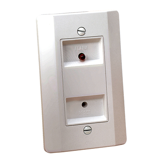
Figure 1. RTS451 Remote Test Station
ALARM
RESET
See Figure 2 for wiring diagram of RTS451 with DH100ACDC
Duct Smoke Detector.
In Canadian applications, the RTS451 is intended to be
located in the same room as the smoke detector and within
60 feet of the unit.
1-800-SENSOR2, FAX: 630-377-6495
www.systemsensor.com
M02-04
TEST MAGNET
LOCATIONS
H0196-00
I56-469-08
Advertisement
Table of Contents

Related Manuals for System Sensor RTS451


Summary of Contents for System Sensor RTS451
- Page 1 1 RTS451 remote test station 1 #4 screw for mounting bracket 1 screw pack (2 mounting screws) 1 M02-04 test magnet See Figure 2 for wiring diagram of RTS451 with DH100ACDC Wiring of RTS451 Duct Smoke Detector. Consult the appropriate detector installation instructions for the applicable wiring diagram.
- Page 2 Place and hold the painted side of the magnet to the until it stops and LED turns off. The RTS451 is capable of RTS451 on the right or left side of the LED as indicated in resetting only certain System Sensor models of detectors.
Need help?
Do you have a question about the RTS451 and is the answer not in the manual?
Questions and answers