
Related Manuals for Dostmann Electronic P705


Summary of Contents for Dostmann Electronic P705
- Page 1 DOSTMANN electronic Precision Measuring Instruments P700, P705, P710, P715, P750, P755, P770, P755-LOG, P770-LOG O p e r a t i o n M a n u a l...
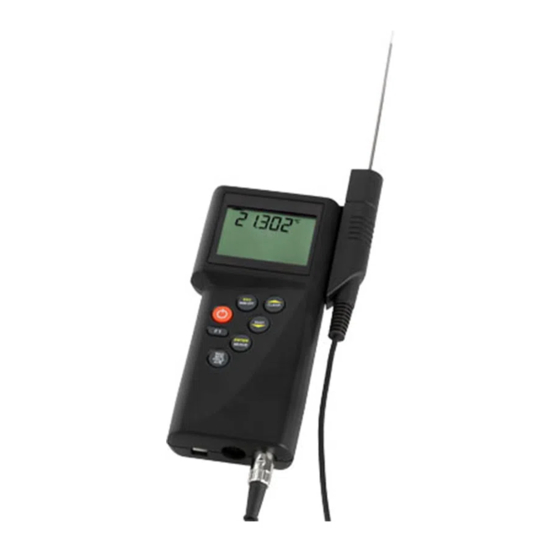
- Page 2 Unit diagram Retractable stand Mounting device for probe handle LC-Display Keyboard Measuring port 1 Measuring port 2 (P705, P715, P755, P770, P755-LOG, P770-LOG) USB PC interface port...
-
Page 3: Table Of Contents
Operation Manual Summary Handling 1.1. General advices 1.2. Setting to work 1.3. Switch on/off 1.4. Menu 1.4.1. Measuring unit switching (UNIT) 1.4.2. Probe selection (Prob) 1.4.3. Difference temperature (Lin2) 1.4.4. Calibration (CAL) 1.4.4.1. Calibration combination probe (temperature/humidity) 1.4.5. Channel activation (Chnl) 1.4.6. -
Page 4: Handling
1. Handling 1.1 General advice • For cleaning the instrument please do not use abra- sive cleaner but a dry or wet piece of cloth. • Please store the measuring instrument in a dry and clean place. • Avoid any force like shocks or pressure to the instru- ment. -
Page 5: Menu
Note: On all instruments you can select the measure- Important! ment category (chapter 1.4.2. Prob) according to the model version. Instruments that are delivered only with one probe the correct measurement category is preset. In other case please check chapter 1.4.2. (Prob) for the correct set-up. -
Page 6: Probe Selection (Prob)
Push [ESC] to be back in the measuring mode. Measurement Probe selection LC-Display Suitable for (Prob) these types of measuring instruments: Temperature Pt100 (RTD) P700/P705/ P750/P755/P770 P755-LOG/P770-LOG Temperature Fe-CuNi Type J for all P700- instruments Temperature NiCr-Ni Type K for all P700- instruments Temperature... -
Page 7: Difference Temperature (Lin2)
Measurement Probe selection LC-Display Suitable for (Prob) these types of measuring instruments: Temperature Cu-CuNi Type T for all P700- instruments Humidity P750/P755/P770 P755-LOG/P770-LOG Flow P750/P755/P770 P755-LOG/P770-LOG Pressure P750/P755/P770 P755-LOG/P770-LOG Thermal flow P750/P755/P770 probe P755-LOG/P770-LOG Note: Please check the probe selection to be sure that Important! the correct probe is entered. -
Page 8: Calibration (Cal)
The instruments offer three calibration options: 1) [OFF]:Standard characteristic curve (e.g. Pt100- resistance according DIN IEC 60751) 2) [OP1]:Calibration by code (2 x four digit code) is equivalent to a 2-point calibration The code is marked clearly by a label on each stan- dard probe. - Page 9 Display-indication with active calibration code (OP1): The CAL -segment and the small 1 on the left indicates to the user that oP1 is activated. Calibration by physical standard references / oP2 Use the up and down keys [ ] to select oP2. Push [ENTER/MENUE] to confirm.
-
Page 10: Calibration
Display-indication with active calibration code (OP2): The CAL-segment and the small 2 on the left indicates to the user that oP2 is activated. 1.4.4.1 Calibration function of the combination probe (humidity/temperature) [CAL] Each humidity probe is a combination probe. That means that beside the humidity sensor these probes also contain a temperature sensor. -
Page 11: Channel Activation (Chnl)
Standard linearization / [oFF Use the up and down keys [ ] to select [oFF. Push [ENTER/MENUE] to confirm. Calibration by code / oP1 Use the up and down keys [ ] to select oP1. Push [ENTER/MENUE] to confirm the desired setting. On the bottom of the display a small 1 appears, after this number a four-digit number (Hex-Code /0..F) is dis- played. -
Page 12: Memory Setup (Lo6)
Push [ENTER/MENUE] and use the up and down keys ] to select ArEA. Push [ENTER/MENUE] to con- firm. On the left corner of the display appears a small 1, which indicates the selected channel. For changing the channel use the up and down keys [ ] . -
Page 13: Measuring Rate (Fast-Modus)
1.5 Recalling the memory data (HOLD MAX MIN AVE) After pushing first time the key [HOLD MAX MIN AVE] the actual value will be hold on the top display line (big display). Pushing again the key [HOLD MAX MIN AVE], the saved maximum-, minimum and average value will be displayed in the bottom display line (small display). -
Page 14: Zero Adjustment
o = Ohm (Pt100) H = Hertz (flow m/s) u = Micro volt (thermocouples) U = Volt (humidity) 1.8.2 Zero adjustment A long press on the F1 button (approx. 3 s) enables you to set the displayed value on 0. Before pressing the button make sure that the actual value also amounts to 0 (no current/pressure at the probe). -
Page 15: Power Supply / Changing The Battery
2. Power supply For the power supply of the instrument a 9 Volt dry bat- tery is used. To exchange the battery switch of the instrument and open the battery cover on the backside of the instrument. Remove and disconnect the battery from the instrument. -
Page 16: Error Codes / Troubleshooting
3. Error Codes By displaying the following error codes the instrument Important! support the operation of the instrument. Error Meaning oPEn no probe or wrong probe is connected - oLo “too low“ – underflow of the measuring range - oHi „too high“... -
Page 17: Technical Data
4. Technical data P700 (1-channel) / P705 (2-channel) Inputs 1/2 Pt100, thermocouple: type K, J, L, N, R, S, T, Measuring range Pt100 -200...+850 °C Thermocouple according DIN (-200...1760°C) Accuracy Pt100 ±0,1 °C from -100 °C...+200 °C 0,1% remaining range... - Page 18 P710 (1-channel) / P715 (2-channel) Inputs 1/2 thermocouple: type K, J, L, N, R, S, T, Measuring range Pt100 ––– Thermocouple according DIN (-200...1760°C) Accuracy Pt100 ––– Thermocouple R, S ––– K, J, L, N, T ±0.2 °C from 0 °C...+200 °C ±0.5 °C to 1000 °C ±1.0°C remaining range Resolution...
- Page 19 P750 (1-channel) / P755 (2-channel) Inputs 1/2 Pt100, thermocouple: type K, J, L, N, R, S, T, humidity, flow resistance, voltage Measuring range Pt100 -200...+850 °C Thermocouple according DIN (-200...1760°C) Resistance 0 ... 400 Humidity 0 %...100 %rH Flow 0 ... 40 m/s Accuracy Pt100 ±0.03°C from -50°C...+199.99°C...
- Page 20 P770 (2-channel) Inputs 1/2 Pt100, thermocouple: type K, J, L, N, R, S, T, humidity, flow Measuring range Pt100 -200...+850 °C Thermocouple according DIN (-200...1760°C) Resistance ––– Humidity 0 %...100 %rH Flow 0 ... 40 m/s Accuracy Pt100 ±0.1 °C from -100 °C...+200 °C otherwise 0.1% Thermocouple R, S...
- Page 21 P755-LOG (2-channel) Inputs 1/2 Pt100, thermocouple: type K, J, L, N, R, S, T, humidity, flow resistance, voltage Measuring range Pt100 -200...+850 °C Thermocouple according DIN (-200...1760°C) Resistance 0 ... 400 Humidity 0 %...100 %rH Flow 0 ... 40 m/s Accuracy Pt100 ±0.03°C from -50°C...+199.99°C...
- Page 22 P770-LOG (2-channel) Inputs 1/2 Pt100, thermocouple: type K, J, L, N, R, S, T, humidity, flow Measuring range Pt100 -200...+850 °C Thermocouple according DIN (-200...1760°C) Resistance ––– Humidity 0 %...100 %rH Flow 0 ... 40 m/s Accuracy Pt100 ±0.1 °C from -100 °C...+200 °C otherwise 0.1% Thermocouple R, S...
-
Page 23: Interface Protocol
5. Interface protocol P700 Measuring value 1 + 2 recognize autom. FC (hex) alternatively ü (ASCII) Enabling the keyboard 0 (hex) Read version number of firmware 6E (hex) alternatively n (ASCII) Read memory (only LOG-instruments) 6C (hex) alternatively l (ASCII) Device serial number S (ASCII) Interface parameter:... -
Page 24: Connector Layout
6. Connector layout Connector layout Pt100 4-wire Measuring channel 1 /2 Pt100 4-Wire Soldering Side Connector layout thermocouple Measuring channel 1 /2 Pt100 2-Wire In the plug Soldering Side NiCr-Ni thermocouple International colours of thermocouples Thermocouple DIN 43 722 DIN 43 710 ANSI MC 96.1 Type R orange... - Page 25 Connector layout of a probe for flow Mini Air6 (series P750/P755/770) Measuring channel 1 /2 Soldering Side yellow white black Mini Air6 Impeller Adaptor DIN Connector for Thermocouples Socket (series P700) Measuring channel 1 /2 Pt100 2-Wire In the plug Soldering Side midget thermocouple connector...
-
Page 26: Data Of Probe-Calibration
7. Data of probe-calibration Our quality-probes are the main reason for the preci- sion and quality of your measuring. To facilitate the exchange of a probe without a loss of precision, our probes were measured in our company and added with a code that describes the characteristic line of the probe. -
Page 27: Guarantee
Dostmann electronic GmbH Waldenbergweg 3b · D-97877 Wertheim No part of this manual may be reproduced without written consent of Dostmann electronic GmbH. The technical data are correct at the time of going to print and may change without prior notice.
Need help?
Do you have a question about the P705 and is the answer not in the manual?
Questions and answers