
Related Manuals for OTT ADC


Summary of Contents for OTT ADC
- Page 1 DOC026.53.80104 OTT Acoustic Digital Current (ADC) Meter 05/2013, Edition 3 (North American Version) 10.500.001.B.U. User Manual...
-
Page 3: Table Of Contents
Table of Contents Specifications ......................3 General information ....................4 Safety information ......................4 Use of hazard information .................... 4 Precautionary labels ....................5 Certification ........................5 Product overview .......................6 System components ....................6 About the sensor ....................8 Temperature compensation .................. 8 Installation ........................8 About the power supply and battery ................8 Battery specifications ................... - Page 4 Operation ........................37 Change the language ..................37 Change the units ....................38 Connect the ADC ....................38 Retrieve ADC data ....................39 Open and view ADC data files ................40 Export data ......................43 Edit screen ......................43 Print a report .......................44 Maintenance .......................44...
-
Page 5: Specifications
Specifications Specifications are subject to change without notice. Specification Details Measurement range: – 0.2 m/s to 2.4 m/s (–0.65 ft/s to 7.87 ft/s) Velocity measurement (Acoustic Accuracy: ±1% of the measured value, ±0.25 cm/s (±0.01 ft/s) Ultrasonic Transducers) Resolution: 0.001 m/s (0.001 ft/s) Frequency: 6 MHz Ultrasonic transducers Beam angle: 20°... -
Page 6: General Information
® ® Windows 2000, Windows XP, Windows Vista, Windows OTT QReview software Functionality: Data transfer from handheld unit, Data check and processing, Data export (XML, ASCII) General information Revised editions are found on the manufacturer’s website. Safety information N O T I C E... -
Page 7: Precautionary Labels
Precautionary labels Read all labels and tags attached to the instrument. Personal injury or damage to the instrument could occur if not observed. A symbol on the instrument is referenced in the manual with a precautionary statement. This symbol, if noted on the instrument, references the instruction manual for operation and/or safety information. -
Page 8: Product Overview
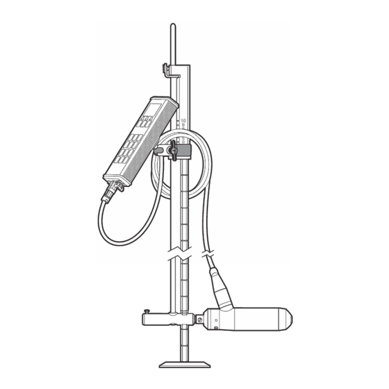
MID and MEAN section discharge calculations. The process used to calculate discharge measurements is based on internationally recognized USGS and ISO748 standards. Mean velocity and depth measurements taken by the OTT ADC, along with the position of a vertical relative to a reference, are used to calculate the discharge. - Page 9 Figure 1 OTT ADC components 1 Location of user documentation and software 6 Wading rod (accessory) 2 USB charging cable 7 Mounting clamp 3 USB download cable 8 Sensor 4 Power charger (not shown, located below handheld 9 ADC handheld unit...
-
Page 10: About The Sensor
6 Temperature sensor Temperature compensation The OTT ADC is equipped with a temperature sensor. Water temperature is an important parameter, both for the calculation of the speed of sound and for the temperature-compensated depth measurement given by the pressure cell. Therefore, a best practice when starting a measurement is to allow the sensor to adjust to the water temperature. -
Page 11: Battery Specifications
Power for both the sensor and handheld unit is provided by a rechargeable battery installed in the handheld unit. A battery symbol in the upper right corner of the display indicates the battery charge level. The charge level can also be viewed by selecting Main menu>System Status>Battery. A fully charged battery can provide more than 14 hours of measurement operation. -
Page 12: To Disconnect The Sensor
Attach the handheld display unit to the wading rod The OTT ADC is supplied with a universal attachment for USGS wading rods. The unit is manufactured with a fixing plate on the rear of the handheld unit that contains a ball head. This arrangement allows the unit to move and rotate in different directions. - Page 13 Figure 4 Attach the handheld unit 1 Wading rod assembly 4 Sensor 2 Handheld unit clamp 5 Wading rod base plate 3 Sensor connection cable 6 Handheld display unit 1. Attach the silver ends of the universal wading rod mounting bracket to the ball on the backside of the handheld display.
-
Page 14: Attach The Sensor To A Wading Rod
Attach the sensor to a wading rod • OTT ADC sensor with sensor end piece. • USGS type standard or top-setting wading rod • Extensions for rod if necessary Refer to Figure 5 for a top-setting wading rod. Refer to Figure 6 for a standard wading rod. -
Page 15: Display Screen
Note: To conserve battery power, the unit is equipped with an automatic shut off feature. If no key presses or communications have occured for 15 minutes while the unit is under battery power, the unit turns off. Remove the USB data cable to make sure this feature operates correctly. Display screen Saved data and current measurement information are shown on the display screen (Figure... -
Page 16: Menu Navigation And Data Entry
Table 1 Symbols and functions (continued) Move Up or Down in multipart menu or Call help list Switch between two display views Start measurement Menu navigation and data entry To select a menu or menu option, press the key with the menu or option number. Some menus, such as the Main Menu and Measurement Settings menus, are divided in to multiple parts. -
Page 17: Main Menu
Main Menu The Main Menu of the OTT ADC is divided in to two windows, each with specific options. The function of the menu options are given in the tables in the steps below. More details can be found in the respective sections of this manual. -
Page 18: Advanced Settings
Option Description Day (1 - 31) Current day Month (0 - 12) Current month Year (0 - 99) Current year Time: 14:22:32 Date: 11/13/08 2. To change the display options, in the System Settings menu, select Display and change or update the entries. -
Page 19: Upgrade Firmware
The current version of the firmware can be viewed through the second Main Menu [2/2]. Select System Status, System Info to view the current version. Information about current or new firmware releases is available at http://www.ott.com. The firmware file name has the naming convention ADC_Vxxx.bin, where xxx is the version number. Do not change the filename. -
Page 20: Performing Measurements
The percentage of the computed discharge for each measured vertical is automatically calculated by the OTT ADC and is shown on the display of the handheld unit when the vertical measurement is complete. -
Page 21: Angle Of Flow
In the field, it may be difficult to achieve flow angles of 0º. In field tests of the OTT ADC, velocity measurement has been found to be unaffected by flow angles of up to 10º. Flow angles of 20º and 30º... -
Page 22: Adjust Quality Thresholds
• Standard Deviation--Indicates measurement accuracy. The standard deviation is calculated only from values that have passed the quality control. • % Discharge per Vertical--Percentage of total discharge in a vertical. Defined ideal standard is less than 5% and no more than 10%. •... -
Page 23: Quick Quality Checks
3. Select option 2, Depth Calibration. Refer to Calibrate the pressure cell (depth calibration) on page 22. The absolute pressure cell built in to the OTT ADC sensor body determines the water and sensor depths. The pressure cell must be calibrated in the existing air pressure conditions to make sure depth readings are accurate. -
Page 24: Internal Quality Check
Calibrate the pressure cell (depth calibration) Water depth is given by an absolute pressure cell built in to the OTT ADC sensor body. The pressure cell must be calibrated to make sure the sensor measurement values are correct. This calibration must be done under the current air pressure conditions with the sensor outside of the water in air. -
Page 25: Turn The Depth Sensor On Or Off
Figure 10 Sensor offset Do the steps below to verify if the offset is correct. 1. Set the OTT ADC to the bottom of the wading rod and rest the rod base on the bottom of the channel or stream. -
Page 26: Perform A Single Point Measurement
Perform a single point measurement Place the handheld unit in Measure mode. 1. Place the sensor in the flow. Make sure the sensor faces upstream and is aligned perpendicular to the cross section. 2. With the sensor in the flow, push the START key. The unit performs a measurement. - Page 27 Figure 12 Example of average flow-velocity calculation, multi-point method There are various ways to arrange the individual points. Methods include the Reduced Measure Points Method, the 2-point KREPS measurement, the Velocity Distribution Method (Multi-point Method), and supplementary methods. More information about each type of method is given below. •...
-
Page 28: Methods Of Discharge Calculation
Methods of discharge calculation Discharge calculation can be done with graphical or arithmetic methods. The OTT ADC supports arithmetic calculation methods including the MEAN section method, and the MID section method. More information about each is given below. MEAN section method (procedure with average cross-section) With this method, the measurement cross-section is divided in individual flow segments. - Page 29 Experience shows that the MID section method gives more exact results when compared to the average cross section method, and requires less calculation time. For these reasons, it is the default setting for the handheld unit of the OTT ADC. Vertical edges and measurements...
-
Page 30: Measurement Settings Menus
Edge characteristics Smooth edge with no vegetation (e.g. concrete, steel, 0.8 - 0.9 cement) Brick sides with vegetation Rough walls with heavy vegetation 0.6 - 0.5 Measurement settings menus Measurement settings [1/3] The Measurement Settings menu is divided into three screens where the basic settings for a discharge measurement are entered. -
Page 31: Measurement Settings [3/3]
Measurement settings [3/3] This is the third screen of the Measurement Settings menu. Update or change the entries for each option. 1. Select Rod Offsets. Rod offsets compensate for the fact that the symmetry axis of the sensor never lies directly on the waterway bed. Option Description Sensor offset (Range... -
Page 32: Field Quality Checks
Note: If necessary, adjust the quality thresholds for the site before the quality check is started. 1. Do a depth calibration. The absolute pressure cell built in to the OTT ADC sensor body determines the water and sensor depths. The pressure cell must be calibrated in the existent air pressure conditions to make sure depth readings are accurate. - Page 33 • Allow time for the temperature sensor of the OTT ADC to adjust to the water temperature (5-6 minutes in extreme conditions). • If conducting a wading measurement, stand so that submerged portions of the body (e.g., legs and feet) give no or minimal resistance to the flow of water that reaches the sensor.
- Page 34 Option Description 4. First Vertical Information about the first vertical is shown in the display. To update an entry, enter the [1/2] option number. 1. Position--Position of the first vertical in feet from the starting edge 2. Depth (if an ICE measurement, refer to the ICE Measurement section)--Depth in feet of the first vertical.
-
Page 35: Perform An Ice Measurement
b. Press OK in any of the Vertical Completed screens to advance to the next point in the discharge measurement. Note: Depending on the measurement mode, the next measure point may be on another vertical. Option Description 1. Review measurement Choose this option to view information about the measurement up to the current measurement point. -
Page 36: Discharge Measurement Window
1. Place the ADC below the ice. 2. From the menu, select WS to bottom of Slush. 3. Move the ADC down in the water column until the SNR is > 10 db and the Corr and Ampl check pass. This establishes the slush boundary. -
Page 37: Qreview Discharge Measurement Summary File
The appearance in the QReview application may be different. Discharge measurement summary Station number Units Date/Time Discharge method OTT ADC (Serial number, firmware) Measurement method Measurement number Averaging interval Operator Mean correlation Start edge... -
Page 38: Delete A File
QReview software Overview The QReview software is used to retrieve data from the ADC and transfer this data to a PC. All measurements, including quality checks, velocity and discharge measurements can be downloaded using the QReview application software. QReview displayed provides basic analysis tools, graphics, one-second time series, reports, and review of potential quality issues. -
Page 39: Qreview Main Menu Options
Settings Select this option to set the Units and Language used in QReview displays. Tools Select this option to update the ADC firmware. Refer to the OTT ADC user manual for more information on how to perform firmware updates. Select this option to connect the ADC to the PC. -
Page 40: Change The Units
4. Close the Select Language window. Change the units Set the units through the Calculations menu. If the open file is an ADC file, only the Units field will be shown. 1. In the menu bar of the QReview main screen, click Settings, then select Calculations. -
Page 41: Retrieve Adc Data
Make sure the correct USB drivers have been installed and make sure the serial port used by the ADC has been identified. 1. Make sure the ADC is connected to the PC and the list of files stored on the unit is shown in the OTT ADC screen. -
Page 42: Open And View Adc Data Files
1. In the menu bar of the QReview main screen, click File, then select Open. The Select File to open screen appears. 2. If necessary, in the File area, click the Data from arrow and select ADC from the drop down menu. - Page 43 Figure 19 File data graphs Table 7 Overview of graphs Parameter Description Mean velocity over the total depth for each vertical. The Velocity (ft/s) arrows indicate the velocity and direction related to the direction of the cross section. Discharge corrected for the width of the measured section.
- Page 44 Note: The settings tab displays two types of data: 1) data controlled by the Q-Review software, and 2) data controlled by the ADC. The data controlled by the ADC appears against a darker background. 6. Select other tabs above the left side graph area to view additional measurement data.
-
Page 45: Export Data
Verticals Data This tab displays the data about each vertical in a table format. Quality issues and ADC warnings are included at the bottom of the window. Field Quality Check This tab displays the data of the latest Field Quality Check (FQC). -
Page 46: Print A Report
Figure 21 Edit screen 3. Change or update the values in the Configuration or Verticals areas. 4. Click Apply in the applicable areas to save the new values. 5. Click Recalculate All to calculate the entire measurement with the new settings and update the graphs. -
Page 47: Handheld Unit Maintenance
Handheld unit maintenance Under normal circumstances, the handheld unit requires minimal maintenance. The following are general considerations and tips that will help keep the unit in good operating condition. • Keep the protective cover on the USB port closed when the connector unit is not in use. •... -
Page 48: Device Warning Messages
Problem Possible cause Action or resolution Check the transducers for contamination or damage. Clean the Ultrasonic transducers may be transducers with an absorbent lint- soiled or damaged free cloth or soft brush. Conduct a Quick Quality Check. Align the sensor at right angles to The measured velocity seems Sensor incorrectly aligned the measurement cross-section. -
Page 49: Measurement Warnings And Errors
Message or error Probable cause Possible actions Accept Angle of sensor orientation compared Repeat measurement to the tag line is too large. Large flow Flow angle > 20º angles may occur near boundaries Go to the next point (measured values such as a start or finish edge. -
Page 50: View System Status
1. Navigate to the second Main Menu [2/2] window and select option 3, System Status. The System Info screen appears. 2. Press OK to return to the Main Menu window. Contact information For technical assistance, repair, information about price and orders for Hydrolab and OTT products: Inside the U.S.A. Hach Hydromet P.O. Box 389... - Page 52 OTT Hydromet Hach Hydromet Ludwigstrasse 16 5600 Lindbergh Drive 87437 Kempten, Germany Loveland, CO 80538 U.S.A. Tel. +49 (0)8 31 5617-0 Tel. (970) 669-3050 Fax +49 (0)8 31 5617-209 (800) 949-3766 (U.S.A. only) info@ott.com Fax (970) 461-3921 www.ott.com sales@hachhydromet.com www.hachhydromet.com ©...
Need help?
Do you have a question about the ADC and is the answer not in the manual?
Questions and answers