Advertisement
Advertisement
Table of Contents

Subscribe to Our Youtube Channel
Related Manuals for Mercury MTB02


Summary of Contents for Mercury MTB02
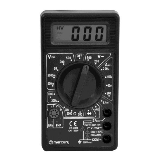
- Page 1 Item ref: 600.101UK & 600.102UK MTB01 & MTB02 DIGITAL MULTITESTERS User Manual...
- Page 2 The performance of the tester may deteriorate after being exposed to any of these elements. When using the test leads, keep your fingers behind the finger guards. Disconnect circuit power and discharge all high-voltage capacitors before testing resistance, continuity, diodes or hFE. MTB01 & MTB02 User Manual...
- Page 3 Operating Environment: 0ºC-40ºC, at <80%RH Storage Environment: -10ºC-50ºC, at <85%RH Power: 9Vdc (1 x PP3 battery supplied) Low battery indication: “ ” Static electricity: about 4mA Dimensions: 126 x 70 x 29mm Weight: 128g (including battery) MTB01 & MTB02 User Manual...
- Page 4 MTB01 & MTB02 User Manual...
-
Page 5: Resolution Accuracy
Accuracies are guaranteed for 1 year, 23ºC ± 5ºC, less than 80% RH. DC Voltage RANGE RESOLUTION ACCURACY 200mV 100uV ± (0.5% of rdg + 3D) 2000mV 10mV ± (0.8% of rdg + 5D) 200V 100mV 500V ± (1.0% of rdg + 5D) MTB01 & MTB02 User Manual... - Page 6 100nA 2000uA ± (1.8% of rdg + 2D) 20mA 10uA 200mA 100uA ± (2.0% of rdg + 2D) 10mA ± (2.0% of rdg + 10D) OVERLOAD PROTECTION: F0.5A/250V & F5A/240V fuse MEASURING VOLTAGE DROP: 200mV MTB01 & MTB02 User Manual...
-
Page 7: Dc & Ac Voltage Measurement
Digital Display along with the voltage polarity. DC CURRENT MEASUREMENT 1. Red lead to “VΩmA”. Black lead to “COM” (for measurements between 200mA and 5A connect red lead to “5A” jack with fully depressed.) MTB01 & MTB02 User Manual... -
Page 8: Resistance Measurement
3. Connect the red test lead to the anode of the diode to be measured and black test lead to cathode. 4. The forward voltage drop in mV will be displayed. If the diode is reversed, figure “1” will be shown. MTB01 & MTB02 User Manual... -
Page 9: Transistor Hfe Measurement
To replace battery & fuse (F500mA/250V for mA terminal and F5A/250V for 5A terminal) remove the 2 screws in the back of the case, simply remove the old fuse or battery, and replace with a new one. Be careful to observe the correct polarity. MTB01 & MTB02 User Manual... - Page 10 The goods must be disposed of according to your local council guidelines. Errors and omissions excepted. Copyright© 2014. AVSL Group Ltd. MTB01 & MTB02 User Manual...
Need help?
Do you have a question about the MTB02 and is the answer not in the manual?
Questions and answers