
Related Manuals for Mercury MTB01


Summary of Contents for Mercury MTB01
- Page 1 MTB01, MTB02 Digital Multimeter Item Ref: 600.101UK, 600.102UK WARNING Please read this manual thoroughly and ensure all contents are fully understood before use of the apparatus.
- Page 2 Warning To avoid possible electric shock or personal injury, and to avoid possible damage to the Meter or to the equipment under test, adhere to the following rules: Before using the Meter inspect the case. Do not ➢ use the Meter if it is damaged or the case (or part of the case) is removed.
- Page 3 behind the finger guards. Disconnect circuit power and discharge all ➢ high-voltage capacitors before testing resistance, continuity, diodes or hFE. Replace the battery as soon as the battery ➢ indicator appears. With a low battery, the meter may produce false readings that can lead to electric shock and personal injury.
- Page 4 General Specifications Max display: LCD 3 ½ digits (1999 count) 0.5” high Polarity: Automatic, indicated minus, assumed plus. Measure method: double integral A/D switch implement. Sampling speed: 2 times per second Over-load indication: “1” is displayed Operating Environment: 0℃~40℃, at <80%RH Storage Environment: -10℃~50℃, at <85%RH Power:...
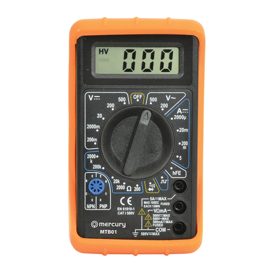
- Page 5 RANGE switch socket 10A jack VΩmA jack COM jack 600.101/102UK User Manual...
- Page 6 Series Multimeters Function Table MODEL ACV DCA OHM √ √ √ √ √ √ √ √ MTB01 √ √ √ √ √ √ MTB02 Technical Specifications Accuracies are guaranteed for 1 year, 23℃±5℃, less than 80%RH DC VOLTAGE RANGE RESOLUTION...
-
Page 7: Audible Continuity
AUDIBLE CONTINUITY RANGE DESCRIPTION Built-in buzzer sounds if resistance is less then 30±20Ω OVERLOAD PROTECTION:15 seconds maximum 220Vrms. DC CURRENT RANGE RESOLUTION ACCURACY 200uA 100nA ±(1.8% of rdg +2D) 2000uA 20mA 10uA 200mA 100uA ±(2.0% of rdg +2D) 10mA ±(2.0% of rdg +10D) OVERLOAD PROTECTION: F0.5A/250V and F5A/250V fuse MEASURING VOLTAGE DROP: 200mV... -
Page 8: Dc Current Measurement
OPERATING INSTRUCTIONS DC & AC VOLTAGE MEASUREMENT 1. Connect red test lead to “VΩmA” jack, Black lead to “COM” jack. 2. Set RANGE switch to desired VOLTAGE position, if the voltage to be measured is not known beforehand, set switch to the highest range and reduce it until satisfactory reading is obtained. -
Page 9: Diode Measurement
3. If the resistance being measured is connected to a circuit, turn off power and discharge all capacitors before measurement. 4. Connect test leads to circuit being measured. 5. Read resistance value on Digital Display. DIODE MEASUREMENT 1. Red lead to “VΩmA”, Black lead to “COM”. 2. -
Page 10: Battery And Fuse Replacement
BATTERY AND FUSE REPLACEMENT Fuse rarely need replacement and blow almost always as a result of operator error. If “ ” appears in display, it indicates that the battery should be replaced. To replace battery & Fuse (F500mA/250V for mA terminal and F5A/250V for 5A terminal) remove the 2 screws in the bottom of the case, simply remove the old, and replace with a new one.