Omron E3X-MDA11 Instruction Sheet
E3x-mda series, digital fiber sensor
Hide thumbs
Also See for E3X-MDA11:
- Datasheet (33 pages) ,
- Installation instructions manual (21 pages)
Table of Contents
Advertisement
Quick Links
Digital Fiber Sensor
E3X-MDA Series
Instruction Sheet
Thank you for selecting an OMRON product.This sheet primarily describes precautions
required in installing and operating the product.
• The specialist who has the knowledge of electricity must treat.
• Please often read this manual, and use it correctly after it understands enough.
• Please keep this manual importantly to refer at any time.
©
OMRON Corporation 2005 All Rights Reserved.
Precautions for Safe Use
Please observe the following precautions for safe use of the product.
1)Do not use the Amplifier Unit in environments subject to flammable or explosive gases.
2)Do not use the Amplifier Unit in environments subject to exposure to water, oil, chemicals, etc.
3)Do not attempt to disassemble, repair, or modify the Amplifier Unit in any way.
4)Do not apply voltages or currents that exceed the rated ranges.
5)Wire the Amplifier Unit correctly, e.g., do not reverse the polarity of the power supply.
6)Connect the load correctly.
7)Do not short both ends of the load.
8)Do not use the Amplifier Unit if the case is damaged.
9)When disposing of the Amplifier Unit, treat it as industrial waste.
Precautions for Correct Use
Please observe the following precautions to prevent failure to operate, malfunction, or undesiable effects on
product performance.
1)The optical fibers are made out of methacrylic resin. Do not use them in atmospheres where organic solvents
are present.
2)Wire the Amplifier Unit separately from power supply or high-voltage lines. If the Amplifier Unit wiring is wired
together with or placed in the same duct as high-power lines, inductive noise may cause operating errors or
damage the Amplifier Unit.
2
3) Do not extend the cable to more than 100 m, and use a wire size of 0.3 mm
or larger for the extension cable.
4)The Amplifier Unit is ready to operate 200 ms after the power supply is turned ON. If the Amplifier Unit and load
are connected to power supplies separately, turn ON the power supply to the Amplifier Unit first.
5)Always keep the protective cover in place when using the Amplifier Unit.
6)Connector Short-circuit Protection (for Amplifier Units with Connectors)
To prevent electric shock or short-circuits, attach the protector seals provided
with E3X-CN-series Connectors to the sides of power supply connectors
that are not being used.
7)Always turn OFF the power supply before connecting, separating, or
adding Amplifier Units.
8)If the data is not written to the EEPROM correctly due to a power failure or
static-electric noise, initialize the settings using the keys on the Amplifier
Unit.
Power supply
9) Using a Mobile Console
connector
Use the E3X-MC11-SV2 Mobile Console for the E3X-DA-S series Amplifier
Units. However, there is a function which cannot be used in part. Other
Mobile Consoles, such as the E3X-MC11, cannot be used.
10) Optical communications are not possible with an E3X-DA-N Amplifier Unit.
11) Depending on the application environment, time may be required for the incident light level to stabilize after
the power supply is turned ON.
12) Do not use thinners, benzine, acetone, or kerosene for cleaning the Amplifier Unit.
13) Do not pull or apply excessive pressure or force (exceeding 9.8 N ・ m) on the Fiber Unit when it is mounted to
the Amplifier Unit.
14) Output pulses may occur when the power is interrupted and so turn OFF the power to the load or load line
before turning OFF the power to the Sensor.
Confirming the Package Contents
•
Amplifier Unit: 1
•
Instruction Sheet (this sheet): 1
1. Ratings and Specifications
Prewired
Separate connector*
Connection method
NPN
E3X-MDA11
E3X-MDA6
Model number
PNP
E3X-MDA41
E3X-MDA8
Light emitting element
Red LED
12 to 24 VDC ±10%, ripple (p-p) 10% max.
Supply voltage
1,080 mW max. (45 mA max. at 24 V)
Power consumption
Open collector (26.4 VDC max.);
Control output
load current: 50 mA max.; residual voltage: 1 V max.
Timer
OFF, OFF-delay, ON-delay, or one-shot
Timer time
1 ms to 5 s
Power tuning
Supported
Supported (optical communications sync method)*2
Mutual interference
prevention
9 Sensors (18 channels)*
3
*1: When using individually or as a master, obtain the E3X-CN21 Master Connector (4-conductor), and when using as a slave, obtain
the E3X-CN22 Slave Connector (2-conductor). Either Connector can be used.
*2: Communications are disabled if SHS is selected for the detection mode, and the communications functions for mutual interference
prevention and the Mobile Console will not function.
*3: Mutual interference prevention can be used for only up to 6 Units if power tuning is enabled.
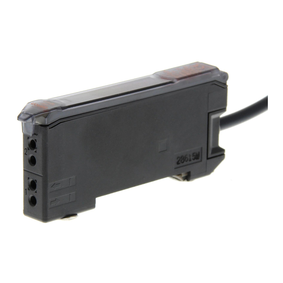
2. Nomenclature
②
Main display (red)
①
Operation indicator
③
Operation indicator for channel 2
for channel 1
④
Sub-display (green)
UP
DOWN
MODE
⑦
Operation keys
1
2
SET
RUN
1
2
⑧
⑤
⑥
Channel selector
Lock button
SET/RUN switch
① Lit when the output for channel 1 is ON.
② Displays the incident light level or the function name.
③ Lit when the output for channel 2 is ON.
④ Displays the incident light level, additional information for detection, or the function
setting for channel 2.
⑤ Used to switch the mode.
⑥ Used to select the channel to display or set.
⑦ Used to change the display, set functions, etc.
⑧ Used to connect and disconnect the Fiber Unit.
3. Basic Operating Information
Setting the Mode
The mode is set using the SET/RUN switch. Set this switch according to the operation to be
performed.
Mode
SET
Select to set detection conditions, to teach the threshold value, etc.
RUN
Select for actual detection operation or to set the following: Manual adjustment of threshold
value, teaching power adjustment, zero reset, or key lock.
Key Operations
1636622-0A
The operation keys are used to switch the displays and set detection conditions. The functions
of the keys depend on the current mode.
Function
Key
RUN mode
UP key
Increases the threshold value.
DOWN key
Decreases the threshold value.
MODE key
Depends on the MODE key setting.
• Teaching
• Executes power tuning.
• Executes a zero reset.
Time to Press Keys
If a specific time for pressing a key is not given in a procedure, press the key for approximately 1 second.
For example, if the procedure says ìpress the UP key,î then press the UP key for approximately 1 second
and then release it.
Reading Displays
The information displayed on the main display and sub-display depends on the current mode.
For the default settings, the RUN mode displays will appear when the power supply is turned
ON for the first time.
Mode
Main display (red)
SET
Displays the incident light level, function name,
Displays threshold value or the setting of the function
or other information depending on the key
displayed on the main display depending on the key
operation.
operation.
For the default setting,the current incident light level for
RUN
For the default setting,the current incident light
Protector seal
level for channel 1 will be displayed
channel 2 will be displayed
(See
note.)
Note: The information that appears on the displays can be set using the display switch
function. Refer to 5. Detailed Settings.
4. Basic Settings
1. Setting the Operation Mode
Select either light-ON or dark-ON operation.
Set as the operation mode in SET mode. Refer to 5. Detailed Settings .
Selection
Description
LON (light-ON)
The output will turn ON when the incident light level is above the threshold.
(default)
DON (dark-ON)
The output will turn ON when the incident light level is below the threshold.
1
2. Adjusting the Power (as Required)
Power tuning can be used to adjust the incident light level that is currently being received to the power
tuning target value (default: 2,000). Before tuning ON the power, always secure the detection object and
Head and be sure that the incident light level is stable.
Setting Method
■
Confirm that the MODE key setting is PTUN (power tuning) in advance. PTUN is the default setting. Refer
to 5. Detailed Settings.
Select the channel for power tuning with the channel selector.
Switch to RUN mode.
SET
RUN
Press the MODE key for at least 3 seconds.
A progress bar will appear on the
sub-display one digit at a time.
(Release the MODE key when the
progress bar appears.)
PTUN
Progress bar
Tuning completed and previous display returns.
The power tuning target value can be changed. Refer to 5. Detailed Settings.
If power is tuned when SHS is selected for the detection method, the power
will be set to the minimum value.
Power tuning will be cleared whenever the detection method is changed from
STND, HRES, or SHS.
•
Power tuning Errors
An error has occurred if one of the following displays appears after the progress bar is displayed.
Flashes twice
Over Error
The incident light level is too low for the power tuning target value.
The power can be increased up to approximately 5 times the incident
light level without power tuning.
PTUN
OVER
Flashes twice
Bottom Error
The incident light level is too high for the power tuning target value.
The power can be decreased down to approximately 1/25th the incident light
level without power tuning.
PTUN
BOTM
■
Clearing Method
Switch to RUN mode
SET
RUN
Hold down the MODE key and press the DOWN key for at least 3 seconds.
+
Description
Note: Press the DOWN key right after pressing the MODE key.
The sub-display will flash twice and power tuning will be cleared.
PTUN
OFF
SET mode
3. Setting Thresholds
Depends on the setting.
• Executes teaching.
1)Manually Setting
• Changes the setting forward.
Depends on the setting.
• Executes teaching.
• Changes the setting in reverse.
Switches the function to be set on the
Setting
SET
RUN
display.
Switch to RUN mode.
Display
2) Teaching
①Teaching With and Without a Workpiece
Teaching can be performed twice, once with and once without a workpiece, and the value
Sub-display (green)
between the two measured values is set as the threshold. RUN mode and SET mode – each
mode can be set up.
PTUN is the default setting. Refer to 5. Detailed Settings.
Setting
Position a workpiece.
RUN
SET
RUN
mode
Switch to RUN
Press the MODE key
mode.
for at least 3 seconds.
SET
SET
RUN
mode
Switch to RUN
mode.
Display
The sub-display will
flash twice.
If the output setting is set to 1-2 (differential operation), the value between the two
differential values when teaching is performed is used as the threshold setting.
②Automatic-teaching(It sets up at move work.)
While continuing pushing a key, the middle of the detected maximum and the minimum
value can be set up as a threshold.
Main Display
Setting
PTUN
Display
During power tuning
alternates at
a fixed
interval.
Power tuning target value
Display
If the output setting is set to 1-2 (differential operation), the value between the
detected maximum and the minimum differential values when teaching is
performed is used as the threshold setting.
③Teaching for Through-beam Sensor Heads
Teaching for a Through-beam Sensor Head is performed without a workpiece. A value
about 6% less than the incident light level with no workpiece is set as the threshold value.
This method is ideal to stably detect very small differences in light level.
Setting
Display
If the output setting is set to 1-2 (differential operation), the differential value
when teaching is performed is used as the threshold setting for channel 2.
④ Teaching for Reflective Sensor Heads
Teaching for a Reflective Sensor Head is performed without a workpiece (i.e., for the
background). A value about 6% greater than the incident light level is set as the threshold
value. This method is ideal to stably detect very small differences in light level.
Setting
Adjust the threshold value with
the UP and DOWN keys.
Increases the
threshold value
Decreases the
threshold value
Display
The information set for the
display switch setting will
return approximately 5
Light level
Threshold
seconds
value
after the threshold is changed.
If the output setting is set to 1-2 (differential operation), the differential value
when teaching is performed is used as the threshold setting for channel 2.
(Same as for Teaching for Through-beam Sensor Heads.)
⑤ Setting the Threshold at the Maximum Sensitivity
The threshold can be set at the maximum sensitivity. This is convenient when using
the longest sensing distance.
Setting
Workpiece
Remove a workpiece.
Display
3 seconds.
3 seconds.
Press the MODE key
for at least 3 seconds.
It does not matter whether or not there is a workpiece.
The value that is set will depend on the detection method and power adjustment
settings.
If the output setting is set to 1-2 (differential operation), no threshold setting is
possible for channel 2.
SET
RUN
Press the UP or
Press the UP or
Switch to RUN
DOWN key.
DOWN key.
mode.
• Teaching Error
After performing teaching, when the following is displayed on sub digital display, the error has occurred.
However, the threshold might not be able to be detected correctly though is set within the possible range.
Threshold
flash twice.
TECH
ー
2PNT
value
The threshold value
that was set will flash
OVER
twice.
flash twice.
flash twice.
PTUN is the default setting. Refer to 5. Detailed Settings.
NEAR
Pushing the MODE key
during 3 seconds or more
Light level
AUTO
AUTO
Threshold
value
It is displayed on a sub
digital value as AUTO, and
Threshold value will flush twice.
the sampling of right level is
effective.
Remove a workpiece
SET
RUN
SET
RUN
Switch to RUN mode.
Switch to RUN mode.
Press the UP or DOWN key.
TECH
ー
THRU
Threshold
value
The sub-display will flash
The threshold value that was
twice.
set will flash twice.
(Same as for Teaching for Reflective Sensor Heads.)
Remove a workpiece
3 seconds
SET
SET
RUN
Press the UP or
Press the UP or DOWN
Switch to RUN
Switch to RUN mode.
DOWN key .
key for at least 3 seconds.
mode.
Threshold
TECH
RFCT
ー
value
The sub-display will flash
The threshold value that
twice.
was set will flash twice.
3 seconds
SET
RUN
SET
RUN
Press the UP or DOWN
Switch to RUN mode.
Switch to RUN mode.
key for at least 3 seconds.
FULL
Threshold
value
The threshold value that was
set will flash twice.
Over error
Light level is too large. Do one of the following and then repeat the
operation.
• Adjust the Head to decrease the incident light level.
• Execute power tuning.
Low error
Light level is too small. Do one of the following and then repeat the
operation.
• Adjust the Head to increase the incident light level.
LO
• Execute power tuning.
Near error
The difference of incident light level is too small. Do one of the
following and then repeat the operation.
• Adjust the Head to increase the difference between the two
incidentlight levels .
RUN
Advertisement
Table of Contents

Related Manuals for Omron E3X-MDA11


Summary of Contents for Omron E3X-MDA11
- Page 1 Hold down the MODE key and press the DOWN key for at least 3 seconds. twice. set will flash twice. Thank you for selecting an OMRON product.This sheet primarily describes precautions Mode Description Note: Press the DOWN key right after pressing the MODE key.
- Page 2 Please refer to separate catalogs for OMRON's safety rated products. INIT GOOD The incident light level as OMRON shall not be responsible for conformity with any standards, codes, or 2. Timer Set separately for each channel. a percentage of the 7.
Need help?
Do you have a question about the E3X-MDA11 and is the answer not in the manual?
Questions and answers