Advertisement
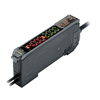
Digital Fiber Sensor
E3X-DA□□-S
Standard models
Instruction Sheet
Thank you for selecting OMRON product.This sheet primarily describes precautions
required in installing and operating the product.
Before operating the product, read the sheet thoroughly to acquire sufficient knowledge
of the product. For your convenience, keep the sheet at your disposal.
TRACEABILITY INFORMATION:
Representative in EU:
Manufacturer:
Omron Europe B.V.
Omron Corporation,
Wegalaan 67-69
Shiokoji Horikawa, Shimogyo-ku,
2132 JD Hoofddorp,
Kyoto 600-8530 JAPAN
The Netherlands
Shanghai Factory
No.789 Jinji Road,
Jinqiao Export Processing District,
Pudong New Area,Shanghai,201206 CHINA
NOTICE:
This is a class A product. In a domestic environment this product may cause
radio interference in which case the user may be required to adequate measures.
©
OMRON Corporation 2011 All Rights Reserved.
2 1 6 6 9 3 6 - 3 A
Precaution on Safety
●Meanings of Signal Words
Indicates a potentially hazardous situation which, if not avoided,
CAUTION
May result in minor or moderate injury or in property damage.
●Alert statements in this Manual
CAUTION
Do not use it exceeding the rated voltage.
There is a possibility of failure and fire.
Do not connect sensor to AC power supply.
Risk of explosion.
Precautions for Safe Use
1)Do not use the Amplifier Unit in environments subject to flammable or explosive gases.
2)Do not use the Amplifier Unit in environments subject to exposure to water, oil, chemicals, etc.
3)Do not attempt to disassemble, repair, or modify the Amplifier Unit in any way.
4)Do not apply voltages or currents that exceed the rated ranges.
5)Do not use the Amplifier Unit in atmospheres or environments that exceedproduct ratings.
6)Wire the Amplifier Unit correctly, e.g., do not reverse the polarity of the power supply.
7)Connect the load correctly.
8)Do not short both ends of the load.
9)Do not use the Amplifier Unit if the case is damaged.
10)When disposing of the Amplifier Unit, treat it as industrial waste.
11)Do not use the sensor in the place exposed to the direct sunlight.
Precautions for Correct Use
1)Do not use the Amplifier Unit under the following conditions.
①In the place exposed to the direct sunlight.
②In the place where humidity is high and condensation may occur.
③In the place where corrosive gas exists.
④In the place where vibration or shock is directly transmitted to the product.
2)Wire the Amplifier Unit separately from power supply or high-voltage lines.
If the Amplifier Unit wiring is wired together with or placed in the same duct
as high-power lines, inductive noise may cause operating errors or damage the Amplifier Unit.
3)For extending wires,use a cable 0.3mm min., and 100m max. in length.
When using the cable as a Korea's S-mark certified product, use the cable of less than 10m
in length.
4)Do not extend the follwing force values applied the cable.Tensile:40 N max.,torque:0.1 Nm
max.,pressure:20 N max.,flexure:3 kg max.
5)The Amplifier Unit is ready to operate 200 ms after the power supply is turned ON. If the
Amplifier Unit and load are connected to power supplies separately, turn ON the power supply
to the Amplifier Unit first.
6)Please turn on the power supply at the same time when you connecting use the amplifier units
with cables.
Mutual interference prevention might not operate normally or mobile console might not be able
to be used when the difference between connected amplifiers at the power supply turning on
time is 30ms or more.
7) Depending on the application environment, time may be required for the light level to
stabilize after the power supply is turned ON.
8)Output pulses may occur when the power is interrupted, so turn OFF the ower to the load or
load line before turning OFF the power to the Sensor.
9)When you use the Amplifier Units with Connectors,
to prevent electric shock or short-circuits, attach
the protector seals provided with E3X-CN-series
Connectors to the sides of power supply
connectors that are not being used.
10)Always turn OFF the power supply before connecting,
Protector seal
separating, or adding Amplifier Units.
Power supply
11)Do not pull or apply excessive pressure or force
connector
(exceeding 9.8 N ・ m) on the Fiber Unit when it is
mounted to the Amplifier Unit.
12) Mobile console E3X-MC11-SV2 doesn't correspond to the new feature such as tough mode
and ON delay OFF delay timer now. E3X-MC11-S cannot be used.
13)Optical communication are not possible with the E3X-DA-N.
Optical communication are possible with the E3X-DA-S or the E3X-MDA.
14)Always keep the protective cover in place when using the Amplifier Unit.
15)Do not use thinners, benzine, acetone, or kerosene for cleaning the
Amplifier Unit.
Confirming the Package Contents
•
Amplifier Unit: 1
•
Instruction Sheet (this sheet): 1
1. Ratings and Specifications
Model
NPN
E3X- DA21-S
E3X- DA7-S
E3X- DA0-S
PNP
E3X- DA51-S
E3X- DA9-S
Control output quantity
2
2
−
External input quantity
1
Connection method
Pre-wired
Wire-saving connector
*1
Connector for communication unit
Light source
Red LED(625nm)
(emission wavelength)
12 to 24 VDC ±10%, ripple (p-p) 10% max.
Power supply voltage
Normal: 960 mW max. (current consumption: 40 mA max. at power supply voltage of 24 VDC,
Power consumption
80 mA max. at power supply voltage of 12 VDC)
ECO1 : 720 mW max. (current consumption: 30 mA max. at power supply voltage of 24 VDC,
60 mA max. at power supply voltage of 12 VDC)
ECO2 : 600 mW max. (current consumption: 25 mA max. at power supply voltage of 24 VDC,
50 mA max. at power supply voltage of 12 VDC)
Control output
Load power supply voltage: 26.4 VDC max.; NPN/PNP open collector;
load current: 50 mA max.; residual voltage: 2 V max. off-stage current: 10µA max.
−
External input
No-voltage input
Protection circuits
Power supply reverse polarity protection, Output short-circuit protection and Output
reverse polarity protection.
Response
Super-high-
Operate or reset: 80 µs
*2
time
speed mode
High-speed
Operate or reset: 250 µs
mode
Standard mode
Operate or reset: 1 ms
High-resolution
Operate or reset: 4 ms
mode
Operate or reset: 16ms
Tough mode
Sensitivity setting
Teaching (2-point teaching, teaching for though-beam sensor heads,
teaching for reflective sensor heads,setting the threshold at the maximum sensitivity,
positioning teaching or automatic-teaching) or munual adjustment
Light emission power and reception gain, digital control method
Functions Power tuning
Differential
Switchable between single edge and double edge detection mode
detection
Single edge: 250µs, 500µs, 1ms, 10ms or 100ms
Double edge: 500µs, 1ms, 2ms, 20ms or 200ms
Timer
No effect, OFF delay, ON delay, one-shot or ON delay OFF delay
Timer time: 1ms to 5s (variable)
Auto power control
High-speed control method for emission current
ATC
Threshold updates at intervals of about 3 s
Zero reset
Negative values can be displayed (Threshold value is shifted, too)
Setting reset
Initial reset or user reset
Mutual interference
Possible for up to 10 Units
*3
prevention
Eco mode
Off, Eco1 or Eco2
*4
Output setting
Output for each channel, Area output or Self-diagnosis output
External input
Various teachings, automatic teaching, power tuning, zero reset,
settings
light emission OFF or ATC start
Operation indicator for channel 1 (orange), Operation indicator for channel 2 (orange)
Indicator
Light level+Threahold, Light level ratio+Threshold,
Digital switch
Peak light level+Bottom light level,
Incident peak light level+No incident bottom light level, Analog bar display,
Light level+Peak light level, Light level+Channel number
7-segment displays (Main display: Red, Sub-display: Green),
Digital display
display direction can be reversed.
Ambient illumination
Incandescent lamp: 10,000 lux max., Sunlight: 20,000 lux max.
(Receiver side)
Ambient temperature
Operating:Groups of 1 to 2 Amplifiers: −25°C to 55°C
Groups of 3 to 10 Amplifiers: −25°C to 50°C
Groups of 11 to 16 Amplifiers: −25°C to 45°C
Storage: −30°C to 70°C (with no icing or condensation)
Ambient humidity
Operating and storage: 35% to 85% (with no condensation)
Insulation resistance
20 MΩ min. (at 500 VDC)
Dielectric strength
1,000 VAC at 50/60 Hz for 1 minute
Destruction: 10 to 150 Hz with a 0.7-mm
Vibration resistance
Destruction: 10 to 55 Hz with a 1.5-mm double amplitude
double amplitude,50m/s² max.acceleration
for 2 hours each in X, Y and Z directions
for 80min each in X, Y and Z directions
Destruction: 500 m/s²
Destruction: 200 m/s²
Shock resistance
3 times each in X, Y and Z directions
Degree of protection
IEC 60529 IP50 (with Protective Cover attached)
Weight (packed state)
Approx. 100 g
Approx. 55 g
Materials
Case
Polybutylene terephthalate (PBT)
Cover
Polycarbonate (PC)
*1: Both the E3X-CN21 Master Connector (4-conductor) and the E3X-CN22 Slave Connector (2-conductor) can be used.
*2: Communications and mutual interference prevention does not function if super-high-speed mode is selected
for the detection mode.
*3: Mutual interference prevention can be used for only up to 6 Units if power tuning is enabled.
*4: Sensing distance is about 1/2 and light level is about 1/3 when the eco-mode is effective.
2. I/O Circuits
■
■
E3X-DA21-S, E3X-DA7-S,E3X-DA0-S ( NPN models)
E3X-DA51-S, E3X-DA9-S ( PNP models)
Brown
Brown
Output for
Black
Output for
channel 1
Black
channel 1
Output for
Orange
Output for
channel 2
12 to
Orange
channel 2
24 VDC
Pink
Pink
External
input *
Blue
Blue
* Only E3X-DA21-S and E3X-DA51-S
3. Dimensions
32.8
3.9×3=11.7
29.8
(Unit: mm)
15.1
3.9×3=11.7
12.15
10
4.3
70
(Pre-wired Models)
8.1
44.3
18.7
36.7
*E3X-DA0-S: Refer to E3X-CRT Operation Manual (E412-E1-01)or E3X-ECT Operation Manual(E413E1-01).
4. Nomenclature
②
Main display (red)
①
③
Operation indicator
Operation indicator for channel 2 (orange)
④
for channel 1 (orange)
Sub-display (green)
UP
DOWN
MODE
⑦
Operation keys
1
2
S E T
RUN
1
2
⑧
⑤
⑥
Lock button
SET/RUN switch
Channel selector
①
Lit when the output for channel 1 is ON.
②
Displays the incident light level,the function name or the change in the incident light lerel.
③
Lit when the output for channel 2 is ON.
④
Display the threshold, the setting of the function displayed on the main disply or threshold ratio.
⑤
Used to switch the mode.
Mode
Description
−
SET
Select for various settings or teaching.
2
RUN
Select for operating, threshold value adjusting or various executings.
−
⑥
Used to select the channel to display or set.
⑦
Used to change the display or set functions.
Function
Key
RUN mode
Increases the threshold or threshold
Depends on the setting.
UP key
ratio.
• Executes teaching.
• Changes the setting forward.
DOWN key
Decreases the threshold or threshold
Depends on the setting.
• Executes teaching.
ratio.
• Changes the setting in reverse.
Execute variously depends on the MODE
MODE key
Switches the function to be set on the
key setting.
display.
−
⑧
Used to connect and disconnect the Fiber Unit.
5. Installing the Amplifier Unit
■
Mounting Units
Catch the hook on the Fiber Unit connector end of the
Unit on the DIN Track and then press down on the
other end of the Unit until it locks into place.
Always attach the Fiber Unit connector end first.
If the incorrect end is attached first, the mounting
strength will be reduced.
■
Removing Units
Press the Unit in the direction indicated by "1"
and then lift up on the Fiber Unit connector end
of the Unit in the direction indicated by "2."
■
Joining Amplifier Units (for Units with Connectors)
Up to 16 Units can be joined.
1. Mount the Amplifier Units one at a time onto the
DIN Track.
2. Slide the Amplifier Units together and press the
Amplifier Units together until they click into place.
Secure the Units with an End Plate (PFP-M) if
there is a possibility of the Amplifier Units moving,
e.g., due to vibration.
Remove the Units in the reverse order.
6. Connecting the Fiber Unit
1. Open the protective cover
2. Press up the lock button.
3. Insert the fiber unit all the way to the back of the
connector insertion opening.
4. Return the lock button to its original position
to secure the fiber unit.
The output will turn ON when the incident light level is above the threshold.
If DIFF (differential operation) is set for the detection method, the output will turn
Approx. 55 g
ON when an edge is detected.
The output will turn ON when the incident light level is below the threshold.
If DIFF (differential operation) is set for the detection method, the output will turn
OFF when an edge is detected.
■
Setting Method
Confirm that the MODE key setting is PTUN (power tuning) in advance.
External
input *
Switch to RUN mode.
12 to
SET
RUN
24 VDC
Press the MODE key for at least 3 seconds.
A progress bar will appear on the
sub-display one digit at a time.
(Release the MODE key when the progress
bar appears.)
PTUN
Progress bar
Tuning completed and previous display returns.
The power tuning target value can be changed. Refer to 8. Detailed Settings.
The light level might change when the detection method is changed.
In that case, execute the power tuning again after changing the detection method.
If SHS is set for the detection method, the power tuning target value will be not have effect
and the power will be set to the minimum value.
•
Power tuning Errors
An error has occurred if one of the following displays appears after the progress bar is displayed.
Over Error
Flashes twice
The incident light level is too low for the power tuning target value.
The power can be increased up to approximately 5 times the incident
light level without power tuning.
PTUN
OVER
Flashes twice
Bottom Error
The incident light level is too high for the power tuning target value.
The power can be decreased down to approximately 1/20th the incident light
level without power tuning.
PTUN
BOTM
■
Clearing Method
Switch to RUN mode
SET
RUN
Hold down the MODE key and press the DOWN key for at least 3 seconds.
+
Note: Press the DOWN key right after pressing the MODE key.
The sub-display will flash twice and power tuning will be cleared.
PTUN
3. Setting Thresholds
1)Manual Setting
Setting
SET
RUN
Switch to RUN mode.
Display
SET mode
2) Teaching
①2-point teaching
Teaching can be performed twice, once with and once without a workpiece, and the value between
the two measured values is set as the threshold. RUN mode and SET mode – each mode can be set up.
Setting
With a workpiece
RUN
SET
RUN
mode
Press the MODE key
Switch to RUN
for at least 3 seconds.
mode.
DIN Track
SET
Hook on the Fiber Unit connector end
SET
RUN
mode
Press the UP or
Switch to SET
DOWN key.
1
mode.
2
TECH
DIN Track
Display
The sub-display will flash.
1
2
If DIFF (differential operation) is set for the detection method, the threshold value
will be set to half of the difference between the two measured values.
②Teaching for Through-beam Sensor Heads
It is performed without a workpiece. The threshold will be set to lower with ratio in the teaching
level setting for the light level of no workpiece. Refer to 8. DetailedSetings.
Setting
SET
RUN
1
2
Switch to RUN mode.
4
3
Display
If DIFF (differential operation) is set for the detection method, the threshold value will
be set to the minimum value that can be detected with stability for the light level of the
without worlpiece.
③ Teaching for Reflective Sensor Heads
It is performed without a workpiece (i.e., for the background). The threshold will be set to upper
with ratio in the teaching level setting for the light level of no workpiece. Refer to 8. DetailedSetings.
Remove a workpiece
Setting
SET
RUN
Press the UP or
Switch to RUN mode.
DOWN key .
Main Display
Display
TECH
The sub-display will flash
PTUN
Display
twice.
During power tuning
alternates at a
fixed interval.
If DIFF (differential operation) is set for the detection method, the threshold value will
be set to the minimum value that can be detected with stability for the light level of the
Power tuning target value
without worlpiece.
④ Setting the Threshold at the Maximum Sensitivity
The threshold can be set at the maximum sensitivity. This is convenient when using the longest
sensing distance.
Setting
SET
RUN
Switch to SET mode.
Display
Execute it by the without workpiece.
The value that is set will depend on the detection method and power tuning settings.
This method cannot be used to set the threshold when the detection method has been set to
DIFF (differential operation).
Adjust the threshold with the
UP key or the DOWN key.
The display set by the display
switch will return in
Light level
Threshold
approximately 5 seconds.
Workpiece
Without a workpiece
Press the MODE key
for at least 3 seconds.
SET
RUN
Press the UP or
Switch to RUN
DOWN key.
mode.
Threshold
ー
2PNT
ratio
The threshold value
that was set will flash
twice.
Without a workpiece
SET
RUN
Press the UP or DOWN key .
Switch to RUN mode.
TECH
ー
THRU
Threshold
value
The sub-display will flash.
The threshold value that was
set will flash twice.
3 seconds
SET
RUN
Press the UP or DOWN key for
Switch to RUN
at least 3 seconds.
mode.
Threshold
RFCT
value
The threshold value that was set
will flash twice.
SET
RUN
Press the UP or DOWN key for at
Switch to RUN mode.
least 3 seconds.
FULL
Threshold
value
The threshold value that was set
will flash twice.
Advertisement
Table of Contents

Related Manuals for Omron E3X-DA21-S


Summary of Contents for Omron E3X-DA21-S
- Page 1 Teaching can be performed twice, once with and once without a workpiece, and the value between ECO1 : 720 mW max. (current consumption: 30 mA max. at power supply voltage of 24 VDC, Thank you for selecting OMRON product.This sheet primarily describes precautions • Changes the setting forward.
- Page 2 ACT setting are the same for both channels . Hold down the MODE key and OMRON shall not be responsible for conformity with any standards, codes, or Press the MODE key for *: The values shown for thresholds, light level, ratio, etc., are examples only. Actual displays may vary.
- Page 3 しきい値 表 示 TECH ー 2.入出力段回路図 1 1) 直射日光のあたる場所では使用 しないで く だ さ い。 RUNモードに切替え 設定されたしきい値が2回 サブデジタルが点滅します 点滅します ■形E3X-DA21-S、 形E3X-DA7-S、 形E3X-DA0-S (NPNタイプ) ■形E3X-DA51-S、 形E3X-DA9-S (PNPタイプ) 「検出機能」に[DIFF](微分動作)を設定している場合、ワークなし状態の受光量に対して 使用上の注意 茶 茶 MODEキーを3秒以上押す 安定して検出できる最小の位置にしきい値が設定されます。 負 荷 負 1) 下記の設置場所では使用 し ないで く だ さ い。...
- Page 4 イ ニシ ャルリ セ ッ ト、 ユーザー リ セ ッ ト ⑥オートマティックティーチング(移動ワークにて設定) イ ニシ ャルリ セ ッ ト : 設定内容をユーザセー ブデータ以外すべて初期化 し、 工場出荷時の状態に戻 し ます。 キーを押し続けている間の受光 量の最大と最 小の中 間を しきい値と して設定します。 あらかじめ、 「 ユーザー リ セ ッ ト : セー ブ した状態に戻 し ます。 MOD Eキー設定...
Need help?
Do you have a question about the E3X-DA21-S and is the answer not in the manual?
Questions and answers