
Related Manuals for Vetus EC3


Summary of Contents for Vetus EC3
-
Page 1: Remote Control
Operation manual installation instructions ENGLISH Electronic engine remote control Copy r ight © 2013 Vet us b. v. S ch ie da m Ho ll a n d... -
Page 2: Table Of Contents
Command station EC3 ........ - Page 3 14.2.1 Parameter A0 ............... . . 63 14.2.2 Parameters to configure the voltage output signal for electronic motors ....64 vetus® Electronic engine remote control...
- Page 4 Drill pattern ..................78 030624.12 vetus® Electronic engine remote control...
-
Page 5: Introduction
The maximum number of engines that the system can control is 2 Command stations The maximum number of command stations in the installation is 3 80 meters Maximum distance between cockpit and engine room vetus® Electronic engine remote control 030624.12... -
Page 6: System Performance
Stroke of gearbox – reverse Throttle stroke Stroke can be set to between 5 and 80 mm Electrical features Power supply 9.0 to 30.0 Vdc Max. current absorbed Current absorbed when the system isn’t loaded 0,5 A 030624.12 vetus® Electronic engine remote control... -
Page 7: Pilot Instructions
Moving the lever from the neutral position, after 16° forward or reverse automatically the electronic system clutches-in respectively the forward or reverse gear. The accelerator lever has a stroke of 62° both in forward and backward direction. Command station EC3 Neutral... -
Page 8: Pilot Instructions With Trolling Option
Reverse Forward Lever functionality with trolling enabled Neutral Trolling can be activated or deactivated either in neutral forward or reverse lever position. To be noticed: at power on, trolling function is automatically active 030624.12 vetus® Electronic engine remote control... -
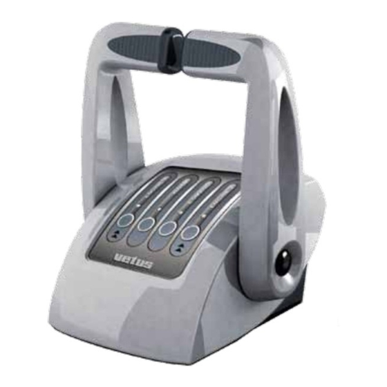
Page 9: Control Keypad
Control keypad On the command station it is mounted an electronic keypad with 4 push-buttons and 4 LEDs. Command station EC3 Command station EC4 without trim option with trim option Trim vetus Engine Engine Engine Engine Warm/Sync Command Warm/Sync Command... -
Page 10: Acquisition Of The Command
Warm-up mode. If you move the lever. it is only affected the accelerator but not the gear. In Warm-up mode the LED Warm/Sync is blinking. After positioning again both levers in neutral and pressing for 1,5 seconds the Warm/Sync, the system comes back to the normal operation mode. 030624.12 vetus® Electronic engine remote control... -
Page 11: Synchro Mode
In order to reset the system, turn off completely (coun- ter-clockwise) knob (A). The emergency lever automati- cally goes back to the position where it was before acti- vating the emergency mode, at the first movement of the command lever. vetus® Electronic engine remote control 030624.12... -
Page 12: Command Station
Depending on the application, it is very important to set the dip-switches present on the bottom part of the command station, as described in sections 4.2 and 8.1 of this manual. Dimensions 4.1.1 Command station EC3 155 (6 ”) 155 (6 ”) -
Page 13: Friction Adjustment
Friction adjustment 4.2.1 Command station EC3 To adjust the inner friction of the command lever, remove the PVC cap (A) and unscrew the fixing screw. It is possible to adjust the friction screwing and unscrewing the inner screw placed into the hole (B). When the regulation will be done, mount the screw and the plastic cap. -
Page 14: Programming Of The Command Station
Important 2: in the same installation can’t coexist a “1st com- mand station FSM” and a “1st command station”. “1st command Code: station FSM” replaces “1st command station” and vice versa. S/N: 030624.12 vetus® Electronic engine remote control... -
Page 15: Command Station Codes
Command station codes Command stations Description Code Command station 1 motor EC3 EC3H1 Command station 1 motor EC3 with TRIM option EC3HT1 Command station 2 motors EC3 EC3H2 Command station 2 motors EC3 with TRIM option EC3HT2 Command station 1 motor EC4... -
Page 16: Actuator
Connections 130 (5 ”) Flexible mounts ”) 25 (1”) Important: the part of the drawing identified with letter (A) doesn’t exist on actuators with mechanical interface either towards the motor or towards the gearbox. 030624.12 vetus® Electronic engine remote control... -
Page 17: Drawing Of Full Electronic Actuator
Drawing of full electronic actuator V2.0 200 (7 ”) 35 (1 ”) 160 (6 ”) 135 (5 ”) 25 (1”) Connections V3.0 200 (7 ”) 35 (1 ”) 160 (6 ”) 135 (5 ”) 25 (1”) Connections vetus® Electronic engine remote control 030624.12... - Page 18 Mount the actuator leaving a space A < 25cm (10”) of at least 25 cm on each side A > 25cm (10”) A < 25cm (10”) Do not install the actuator with the connectors upwards 030624.12 vetus® Electronic engine remote control...
-
Page 19: Actuator Labels
Actuator for 2 mechanical motors and 2 gearbox solenoid driven (with trim) EC3UMET2 Actuator for 1 electronic motor (V) and 1 gearbox solenoid driven (no trim) EC312EE Actuator for 1 electronic motor (V) and 1 gearbox solenoid driven (with trim) EC312EET vetus® Electronic engine remote control 030624.12... -
Page 20: Electronic Actuator Boards
4 poles GND CH2 GND CH1 Important: channels 1 and 3 are dedicated to the electronic engine (ECU) while the channels 2 and 4 are dedicated to the inverter for electric motors (hybrid motor applications). 030624.12 vetus® Electronic engine remote control... -
Page 21: Relays Pcb Version 1.0 For Electronic Gearboxes
Relay port gearbox Relay starboard gearbox Solenoid gearbox Trim command Forward (brown) Trim “-“ (nero) Vdc (yellow/green) Vdc (brown) Reverse (blue) Trim “+” (grey) Trim “–“ (brown) Trailer (yellow/green) Vdc (yellow/green) Trim “+” (blue) vetus® Electronic engine remote control 030624.12... -
Page 22: Relays Pcb Version 2.0 For Electronic Gearboxes
Right engine - Common neutral relays contact Right engine - NC contact neutral relays Right engine - Common trim contact Right engine - Trim + Right engine - Trim - Right engine – Trailer 030624.12 vetus® Electronic engine remote control... -
Page 23: Relays Pcb Version 3.0 For Electronic Gearboxes With Trolling Option
Neutral relais – NC contact – Right (Wire ID 3, “Gearbox + neutral” connector) Connect to VDC (Pin 1) Forward Right (Wire ID 1, “Gearbox + neutral” connector) Backward Right (Wire ID 2, “Gearbox + neutral” connector) (Not connected) vetus® Electronic engine remote control 030624.12... -
Page 24: Canbus Pcb For Motor With Canbus Interface
• Electronic ECU with CANBus interface • Command of hybrid motors frequency converter driven through a voltage signal The PCB is mounted inside of the actuator and there aren’t any special precaution to follow durig commissioning. 030624.12 vetus® Electronic engine remote control... -
Page 25: Accessories And Options
Connector for throttle cables Polarization Wall mounted connector Cable connector Connector for CANbus data transmission cable Polarization Wall mounted connector Cable connector vetus® Electronic engine remote control 030624.12... -
Page 26: Canbus Data Transmission Cable
L=3 m DTCAN3M L=5 m DTCAN5M L=10 m DTCAN10M Cable actuator – electronic motor (V), Electronic throttle universal Grey Black Length Code L=3 m EC3E3U Important: this cable is without connector on motor side 030624.12 vetus® Electronic engine remote control... -
Page 27: Vf - Throttle Canbus Command Cable
For the connection towards the gearbox solenoid driven, please refer to section 10.2.3. of this manual. Yellow/Green Black 1 Black 2 Length Code L=3 m EC3G3M Important: this cable is without connector on gearbox side 6.3.1 VF – Cable for gearbox solenoid driven Length Code L=3 m EC3G3M vetus® Electronic engine remote control 030624.12... -
Page 28: Actuator - Trolling Valve Cable & Actuator Box - Trim/Flap Cable
The cable for the trim pump of Mercruiser sterndrive has a length of 3 meters; in the cabling are included the fast-on con- nections to the microswitch for the end of stroke. Yellow Blue Actuator side Mercruiser® pump side Length Code L=3 m EC3T3MM 030624.12 vetus® Electronic engine remote control... -
Page 29: T-Splitter
For the connection towards the gearbox solenoid driven, please refer to section 10.2.3. of this manual. Black 1 Black 2 Black 3 Black 4 Black 5 Black 6 Yellow/Green Length Code L=3 m ECG3/6 Important: this cable is without connector on gearbox side vetus® Electronic engine remote control 030624.12... -
Page 30: Flap Actuator Box Option
It follows here below a drawing of the installation kit: The actuator for trim/flap option looks according to the below drawing: Trim/Flap Trim/Flap Data transmission left engine right engine Canbus Trim/Flap Trim/Flap +12 V +24 V Voltage supply 030624.12 vetus® Electronic engine remote control... -
Page 31: Installation Scheme
V DC Gearbox: Yellow/Green V DC Trim ap: Brown Forward: Black 1 Trim + : Black 2 or Grey Reverse: Black 2 Forward Reverse Trim - : Black 1 or Black) Trim/Flap + Trim/Flap - vetus® Electronic engine remote control 030624.12... -
Page 32: Trim/Flap Option
For installations with two engines, in case of “Synchro” mode operation, the buttons on the right-hand side operate the trims of both engines simultaneously. Command station EC3 Version for one engine Version for two engines... -
Page 33: System Types And Installation Schemes
• Up to 3 command stations and 2 engines with mechanical throttle, mechanical gearbox, with/without trim; • Up to 3 command stations and 2 hybrid engines with mechanical throttle, mechanical gearbox, analogue outputs for electric engine inverter driven, with/without trim. vetus® Electronic engine remote control 030624.12... -
Page 34: Installation With 2 Mechanical Actuators - Solution B
JP19: NO (end-line) JP19: NO (end-line) Data transmission cable Code: DTCANxx This installation scheme is valid for systems with: • Up to 3 command stations and 2 engines with mechanical throttle, mechanical gearbox, with/without trim; 030624.12 vetus® Electronic engine remote control... -
Page 35: Installation With 2 Mechanical Actuators - Solution C
JP19: YES (end-line) Data transmission cable Code: DTCANxx This installation scheme, typical for catamaran applications, is valid for systems with: • Up to 3 command stations and 2 engines with mechanical throttle, mechanical gearbox, with/without trim; vetus® Electronic engine remote control 030624.12... -
Page 36: Installation With 1 Actuator - Solution D
• up to 3 command stations and 1or 2 engines with electronic throttle (voltage), mechanical gearbox, with/without trim (or flap); • up to 3 command stations and 1 or 2 engines with electronic throttle (voltage), solenoid driven gearbox, with/without trim (or flap); 030624.12 vetus® Electronic engine remote control... -
Page 37: Installation With 1 Actuator - Solution E
• up to 3 command stations and 1or 2 engines with electronic throttle (voltage), mechanical gearbox, with/without trim (or flap); • up to 3 command stations and 1 or 2 engines with electronic throttle (voltage), solenoid driven gearbox, with/without trim (or flap); vetus® Electronic engine remote control 030624.12... -
Page 38: Installation With 2 Actuators - Solution F
Actuator for flap option JP14: NO (address) JP19: YES (end-line) Data transmission cable Code: DTCANxx This installation scheme is valid for systems with up to 3 command stations and 2 engines and gearboxes, full electronic 030624.12 vetus® Electronic engine remote control... -
Page 39: Installation With 2 Actuators - Solution G
Actuator for flap option JP14: NO (address) JP19: NO (end-line) Data transmission cable Code: DTCANxx This installation scheme is valid for systems with up to 3 command stations and 2 engines and gearboxes, full electronic vetus® Electronic engine remote control 030624.12... -
Page 40: Configuration Of The Canbus Network: End Of Line Termination Resistor And Address Setting Of
This is the typical application where there are motors and/or gearboxes with electronic interface (like it is described in sections 7.4 and 7.5). In case of systems with two propulsion systems equipped with mechanical motors and mechanical gearboxes, you need to use two mechanical 030624.12 vetus® Electronic engine remote control... -
Page 41: Configuration Of The Actuator
Enable the address short-circuiting terminals 5 and 6 of JP3 Enable the 120 Ω short-circuiting either terminals 8 and 9 of JP5 or terminals 2 JP19: YES (end-line) and 3 of JP3 JP13 JP11 JP10 End-line resistance (120 Ω) Address vetus® Electronic engine remote control 030624.12... - Page 42 JP14 = ON The setting of JP19 is depending if the actuator is in the middle (JP19 = OFF) or at the end of the CANBus network (JP19 = ON) 030624.12 vetus® Electronic engine remote control...
-
Page 43: Push-Pull Cables Installation
6. loose the emergency knob and move the emergency lever until the device will reach the correct position (it will be automatically locked) Important: before the assembly, the throttle must be in minimum position and the gearbox must be in neutral position. vetus® Electronic engine remote control 030624.12... -
Page 44: Push-Pull Cable Outgoing From The Mercruiser® Stern Driver
6. lock the aluminium device with the screw, the brass spacer and the washer at the distance indicated into the picture; 7. loose the emergency knob and move the emergency lever until the device reaches the correct position (it will be automatically locked) 030624.12 vetus® Electronic engine remote control... -
Page 45: Johnson® Push-Pull Cable
5. lock the aluminium device with the screw, the brass spacer and the washer at the distance indicated into the picture; 6. loose the emergency knob and move the emergency lever until the device reaches the correct position (it will be automatically locked) vetus® Electronic engine remote control 030624.12... -
Page 46: Electrical Installation
‘N’ marked with in red) of the system on the boat. Important: take care to connect properly the polarity of the cables (supply is marked with a red sign). 030624.12 vetus® Electronic engine remote control... - Page 47 ‘R1’ is a relay that is activated by the key of the port engine starboard engine while ‘R2’ is a relay that is activated by the key of the star- board engine Actuator Actuator Actuator Battery Battery Battery Battery Portside engine Starboard engine Portside engine Starboard engine vetus® Electronic engine remote control 030624.12...
-
Page 48: Electrical Installation Of Systems With 1 Motor, 1 Actuator And 1 Dashboard
12 V power supply 24 V power supply Diode 10 A, 20 V 5 A, 24 V Relè 10 A, 12 V 5 A, 24 V Fuse 10 A Supply cable cross section 2.5 mm 1.5 mm 030624.12 vetus® Electronic engine remote control... -
Page 49: Electrical Installation Of Systems With 2 Motors, 1 Or 2 Actuators And 2 Dashboards
10.1.3 Electrical installation of systems with 2 motors, 1 or 2 actuators and 2 dashboards Actuator The same scheme can be used in case there are 2 actuators instead of only one. For the detailed list of components, please refer to the table at section 10.1.2. vetus® Electronic engine remote control 030624.12... -
Page 50: Electrical Installation Of Systems With 1 Motor, 1 Actuator And 2 Dashboards
10.1.4 Electrical installation of systems with 1 motor, 1 actuator and 2 dashboards Actuator For the detailed list of components, please refer to the table at section 10.1.2. 030624.12 vetus® Electronic engine remote control... -
Page 51: Dimensional Criteria Of The Power Cables For The Overall Installation
• In case of systems with electronic throttle, it is very important to connect to a common GND point (GND buss bar) all the negative poles (GND) of every electronic equipment. Bow thruster Buss bar for GND Motor starter Actuator vetus® Electronic engine remote control 030624.12... -
Page 52: Electrical Cabling Of The Outgoing Cables From The Actuator
• mechanical motor and mechanical gearbox (only 1 propulsion group per actuator) • mechanical engine and solenoid driven gearbox (up to 2 propulsion groups per actuator) • electronic engine and mechanical gearbox (up to 2 propulsion groups per actuator) 030624.12 vetus® Electronic engine remote control... -
Page 53: Cabling Of Actuators V2.0 For Electronic Propulsion Systems
Gearbox + Neutral Throttle Data transmision Clutch Throttle CANBus +12 V Clutch Throttle Fuse Gearbox + Neutral Throttle Fuse Voltage supply Important: in case of single engine installation, use only the connectors for the right engine. vetus® Electronic engine remote control 030624.12... -
Page 54: Cabling Of Actuators V3.0 For Electronic Propulsion Systems
Forward GND signal (solenoid valve) Neutral relais Reverse GND signal (solenoid valve) N° 1 cable for the PWM command of the trolling (2 wire used) Wire identifier Function BROWN Trolling command PWM signal BLUE Trolling command GND 030624.12 vetus® Electronic engine remote control... -
Page 55: Cabling Scheme From Actuator To Gearbox, From Actuator To Trim Or From Actuator To Flap
V DC Gearbox: Yellow/Green V DC Trim ap: Brown Forward: Black 1 Trim + : Black 2 or Grey Reverse: Black 2 Forward Reverse Trim - : Black 1 or Black) Trim/Flap + Trim/Flap - vetus® Electronic engine remote control 030624.12... -
Page 56: Programming Of The Actuator, General Guidelines
5. to set the other parameters, scroll the menu using the keys “1” and “2” and when the parameter that you would like to change is reached, follow this procedure starting from the point 3. 030624.12 vetus® Electronic engine remote control... -
Page 57: Actuator Parameters
It is shown an underscore “_” or It is shown an underscore “_” or the left lever position if it is the the right lever position if it is the actuator of the portside engine actuator of the starboard engine vetus® Electronic engine remote control 030624.12... -
Page 58: Setting Of The Strokes Of Push-Pull Cables
(potentiometer); e. When the hole on the fork (or the ball joint) is aligned with the hole on the throttle lever (potentiometer), store the position with key “3”. 030624.12 vetus® Electronic engine remote control... -
Page 59: Setting Of The Stroke Of The Gearbox Cable
Important 6: in case of stern drive and outboard engines, if the motor isn’t running, it isn’t possible to set the strokes, because the clutch-in operation becomes very hard. In this is the case, actuate the rotation of the propeller manually, this will make easier the clutch-in of the gearbox. vetus® Electronic engine remote control 030624.12... -
Page 60: Programming Of The Actuator In Installations With Mechanical Motor And Gearbox
(gearbox forward and motor accelerated). Value A0 Throttle Gearbox Push (direction Pull (direction Push (direction Push (direction Pull (direction Push (direction Pull (direction Pull (direction The factory settings provide A0 = 4 Throttle Gearbox 030624.12 vetus® Electronic engine remote control... -
Page 61: Specific Parameters
0 .. 9.9 s 0.0 s Proportional coefficient 0 .. 99 These para- meters must not Integral coefficient 0 .. 99 be changed To be used for the check-up of the internal CANBus communication vetus® Electronic engine remote control 030624.12... -
Page 62: Programming Of Actuators For Installations With Electronic Motor And Mechanical Gearbox
These parameters are present only in systems with electronic engine (ECU) and/or electric with electrical engine inverter driven. Parameters to define the voltage output interface will be detailed in the following pages. To be used for the check-up of the internal CANBus communication 030624.12 vetus® Electronic engine remote control... -
Page 63: Parameter A0
Positions of the left gearbox are in- verted while the positions of the right Set A0=2 gearbox are correct Positions of both gearboxes are in- Gearbox Set A0=1 Gearbox verted starboard port engine engine vetus® Electronic engine remote control 030624.12... -
Page 64: Parameters To Configure The Voltage Output Signal For Electronic Motors
Important: the graphic on the right represents the volt- age profile defined by parameters L,C, H. Changes of factory values could cause a system malfunctioning. Be- fore making any changes, contact our technicians. Stroke lever 030624.12 vetus® Electronic engine remote control... -
Page 65: Programming Of Actuators For Mechanical Motors And Electronic Gearbox
Delay in neutral; it occurs any time you move directly from forward to reverse or from reverse to forward. 0 .. 9.9 s 0.5 s This delay does not occur when from neutral you move to forward or reverse. vetus® Electronic engine remote control 030624.12... -
Page 66: Programming Of Actuators With Electronic Motor And Electronic Gearbox
These parameters are present only in system with electronic engine with ECU and/ or electric engine inverter driven. Parameters for the voltage outputs are described at section 14.2.2. To be used for the check-up of the internal CANBus communication 030624.12 vetus® Electronic engine remote control... -
Page 67: Programming Of Actuators With Electronic Canbus Motor And Mechanical Gearbox
Necessary information for majority of the motors are minimum speed and maximum speed without load. Byte 2 and byte 3 are used to transfer the speed reference. Bytes 1, 4, 5, 6, 7, 8 are commonly not used. vetus® Electronic engine remote control 030624.12... -
Page 68: Setting Of The Canbus Parameter Values
Termination resistor is already mounted on the CANBus interface card but it can be removed, if necessary. The CANBus interface card pin-out is described at section 5.5.5. 17.2.4 Wiring of the outgoing actuator cables Please refer to section 10.2. 030624.12 vetus® Electronic engine remote control... -
Page 69: Connection To Vf Motors Through Canbus Interface
For more information look at VF Norm A049 and at the Application Note 3 – Installation on VF motors with CANBus inter- face dated 2009/10/11. ON = the command from electronic control lever is disables (it doesn’t work properly) OFF = the command from electronic control lever is enabled (it works properly) vetus® Electronic engine remote control 030624.12... -
Page 70: Programming Of Actuators With Electronic Canbus Motor And Electronic Gearbox
For parameter setting, please refer to section 17.2. 18.2 Electronic gearbox parameters For parameter setting, please refer to section 15.2. 18.3 Wiring of the actuator outgoing cables For wiring of the cables outgoing from the actuator refer to section 10.2. 030624.12 vetus® Electronic engine remote control... -
Page 71: Programming Of Actuators For Installations With Trim Or Flap Command Option
Use electrical cables between actuator and trim pump or from actuator and flap pump as specified in sections 6.4, 6.5. and 10.2.2. Verify that wiring is according to electrical scheme reported at section 10.2.3. vetus® Electronic engine remote control 030624.12... -
Page 72: Programming Of The Trolling Functions
It defines for how much time can be applied the “kick-off” before entering in trolling mode. Parameter “t4” In some application it might be useful to slightly change the motor speed during the trolling ramp. When motor is idling, 030624.12 vetus® Electronic engine remote control... - Page 73 Parameter t7 as no meaning out of trolling mode. Important note: don’t exceed the maximum input speed for your trolling valve system! Check carefully cor- responding technical data and set t7 correctly! vetus® Electronic engine remote control 030624.12...
-
Page 74: Behaviour Of The Electronic System In Case Of Failures
In case this alarm is activated, turn off the system, verify the causes that have generated the alarm before turning on again the system. 030624.12 vetus® Electronic engine remote control... -
Page 75: Troubleshooting
Minimum speed position on the com- • Scheme at section 13.2 or 15.1 according to the scheme mand stations corresponds to maximum speed on the actuator • Check settings of parameter A0 • Section 14.2.1 vetus® Electronic engine remote control 030624.12... -
Page 76: Led Diagnosis On Command Station
Green LED on command Might be a problem on the posi- station is blinking (50% ON, tioning measuring device of the Contact Vetus 50% OFF) command station There is a failure on mechanical To remove the failure refers at... -
Page 77: How To Start
8) program the actuator specific installation parameters (from section 13 to section 18 included) 9) make the programming of the options, if your application requires it (sections 19 and 20) 10) once you have set-up the electronic system, read the pilot instruction (section 3) and, good navigation! vetus® Electronic engine remote control 030624.12... -
Page 78: Drill Pattern
Drill pattern 65 (2 ”) 22 ( ”) 030624.12 vetus® Electronic engine remote control... - Page 79 76.5 (3”) 74 (2 ”) ø 6 ( ”) 4 x vetus® Electronic engine remote control 030624.12...
- Page 80 280 ( ø 6,2 ( ”) 4 x 030624.12 vetus® Electronic engine remote control...
- Page 81 (11”) vetus® Electronic engine remote control 030624.12...
- Page 82 030624.12 vetus® Electronic engine remote control...
- Page 83 Electronic engine remote control 030624.12...
Need help?
Do you have a question about the EC3 and is the answer not in the manual?
Questions and answers