Vetus EC3 Manuals
Manuals and User Guides for Vetus EC3. We have 2 Vetus EC3 manuals available for free PDF download: Operation Manual And Installation Instructions

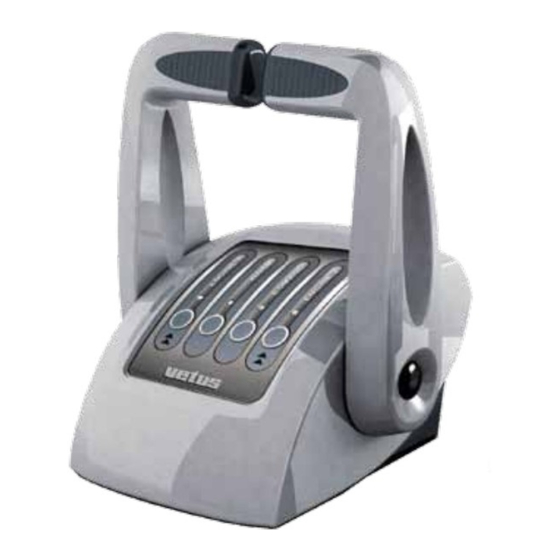
Vetus EC3 Operation Manual And Installation Instructions (84 pages)
Electronic engine remote control
Brand: Vetus
|
Category: Marine Equipment
|
Size: 4 MB
Table of Contents
Advertisement

Vetus EC3 Operation Manual And Installation Instructions (84 pages)
Electronic engine remote control
Brand: Vetus
|
Category: Remote Control
|
Size: 4 MB
Table of Contents
Advertisement