Tektronix 1741C User Manual
Analog dual-standard waveform monitor
Hide thumbs
Also See for 1741C:
- Technical reference (47 pages) ,
- Service manual (70 pages) ,
- Declassification and security instructions (13 pages)
Table of Contents
Advertisement
Quick Links
Download this manual
See also:
Service Manual
Advertisement
Table of Contents

Related Manuals for Tektronix 1741C


Summary of Contents for Tektronix 1741C
- Page 1 1741C Analog Dual-Standard Waveform Monitor User Manual *P071262600* 071-2626-00...
- Page 3 1741C Analog Dual-Standard Waveform Monitor User Manual Revision A www.tektronix.com 071-2626-00...
- Page 4 Copyright © Tektronix. All rights reserved. Licensed software products are owned by Tektronix or its subsidiaries or suppliers, and are protected by national copyright laws and international treaty provisions. Tektronix products are covered by U.S. and foreign patents, issued and pending. Information in this publication supersedes that in all previously published material.
- Page 5 Tektronix, with shipping charges prepaid. Tektronix shall pay for the return of the product to Customer if the shipment is to a location within the country in which the Tektronix service center is located. Customer shall be responsible for paying all shipping charges, duties, taxes, and any other charges for products returned to any other locations.
-
Page 7: Table Of Contents
Connecting Directly to a PC ................. Tutorial: Timing a Studio ..................Reference ......................Monitoring Safe Area Compliance ................. Appendix A: Alarms ....................Configuring Alarms ..................Monitoring Alarms ................... Appendix B: Upgrading Instrument Software..............USB Upgrade....................Network Upgrade ..................... 1741C Analog Dual-Standard Waveform Monitor User Manual... - Page 8 Table of Contents Upgrading Multiple Instruments with a PC..............Verifying the Upgrade ..................Glossary Index 1741C Analog Dual-Standard Waveform Monitor User Manual...
- Page 9 List of Figures Figure 1: 1741C front panel ..................Figure 2: 1741C rear panel ..................Figure 3: Status bar in Single input mode ..............Figure 4: Status bar in Multi input mode ............... 1741C Analog Dual-Standard Waveform Monitor User Manual...
- Page 10 Table 7: Pix Mon connector pin assignments ..............Table 8: Remote connector pin assignments ..............Table 9: Pin assignments ..................Table 10: Display elements..................Table 11: Status bar icons ..................Table 12: Alarms and Description ................1741C Analog Dual-Standard Waveform Monitor User Manual...
-
Page 11: General Safety Summary
Do not operate in an explosive atmosphere. Keep product surfaces clean and dry. Provide proper ventilation. Refer to the manual’s installation instructions for details on installing the product so it has proper ventilation. 1741C Analog Dual-Standard Waveform Monitor User Manual... - Page 12 DANGER indicates an injury hazard immediately accessible as you read the marking. WARNING indicates an injury hazard not immediately accessible as you read the marking. CAUTION indicates a hazard to property including the product. The following symbol(s) may appear on the product: 1741C Analog Dual-Standard Waveform Monitor User Manual...
-
Page 13: Compliance Information
United Kingdom To ensure compliance with the EMC standards listed here, high quality shielded interface cables should be used. Inrush current: Not to exceed 6 A at 240 V 50 Hz mains supply. 1741C Analog Dual-Standard Waveform Monitor User Manual... - Page 14 Complies with the EMC provision of the Radiocommunications Act per the following standard, in accordance with ACMA: Declaration of Conformity – EMC EN 55022:1987. Radiated and conducted emissions, Class B, in accordance with EN 55103-1:1996. viii 1741C Analog Dual-Standard Waveform Monitor User Manual...
-
Page 15: Safety Compliance
IEC 61010-2-032: 2002. Particular requirements for handheld current clamps for electrical measurement and test equipment. Equipment Type Test and measuring equipment. Safety Class Class 1 – grounded product. 1741C Analog Dual-Standard Waveform Monitor User Manual... - Page 16 Measurement Category II. For measurements performed on circuits directly connected to the low-voltage installation. Measurement Category I. For measurements performed on circuits not directly connected to MAINS. Overvoltage Category Overvoltage Category II (as defined in IEC 61010-1) 1741C Analog Dual-Standard Waveform Monitor User Manual...
-
Page 17: Environmental Considerations
See www.dtsc.ca.gov/hazardouswaste/perchlorate for additional information. Restriction of Hazardous This product has been classified as Monitoring and Control equipment, and is outside the scope of the 2002/95/EC RoHS Directive. Substances 1741C Analog Dual-Standard Waveform Monitor User Manual... - Page 18 Compliance Information 1741C Analog Dual-Standard Waveform Monitor User Manual...
-
Page 19: Preface
Preface Preface About This Manual This manual describes the installation and operation of the 1741C Analog Dual-Standard Waveform Monitor. It contains the following sections: Getting Started provides a product description and a list of available options and accessories. Operating Basics describes installation, basic instrument operation, instrument controls and connectors, and general menu features. - Page 20 Preface 1741C Analog Dual-Standard Waveform Monitor User Manual...
-
Page 21: Getting Started
SCH phase, and picture functions. The four-tile FlexVu™ display and convenient picture thumbnail maximize the versatility of the 1741C. You can configure your instrument to display one, two, three, or four waveforms simultaneously and overlay just as many vector displays. -
Page 22: Standard And Optional Accessories
1741C Analog Dual-Standard Waveform Monitor Product Documentation CD kit. (English: Tektronix part number 020-2981-XX; Simplified Chinese: Tektronix part number 020-2997-XX). The CD in this kit contains the following documents in PDF format. (All documents are in English unless noted otherwise): User manual (English and Simplified Chinese) -
Page 23: Operating Considerations
Up to 40,000 feet (12,192 meters) Cooling Variable Fan. Forced air circulation with no air filter. Required Clearances Do not block the bezel or rear panel vent holes, or more than half the vent holes on the sides 1741C Analog Dual-Standard Waveform Monitor User Manual... -
Page 24: Installation
2, International Power Plug Options.) The typical power draw is 50 watts. Refer to the Specifications and Performance Verification Technical Reference document on the Product Documentation CD for additional information on power and environmental requirements. 1741C Analog Dual-Standard Waveform Monitor User Manual... - Page 25 The termination must be 75 Ω and DC coupled. An appropriate termination would be Tektronix part number 011-0102-03. It is a 75 Ω, end-of-line termination for analog video.
-
Page 26: Incoming Inspection
The waveform monitor must have been operating for a warm-up period of at least 20 minutes, and must be operating at an ambient temperature. Use the following procedures to check the basic functionality of 1741C waveform monitors. The checks are arranged by model and option so that you can choose the sections that are appropriate for your instrument. -
Page 27: Table 2: Required Test Equipment
CONFIG > Utilities > View Diagnostics Log > SEL. 7. After the diagnostics are finished, the instrument state is restored. When the progress indicator in the status bar is finished, the instrument has finished initializing. 1741C Analog Dual-Standard Waveform Monitor User Manual... - Page 28 5. Set the waveform monitor for an all black screen: a. Select Utilities > Screen Solid Color > Select Color > Black. b. Press the SEL button. 6. Count any pixels stuck high (not black). 1741C Analog Dual-Standard Waveform Monitor User Manual...
-
Page 29: Table 3: Lcd Visual Defects
For irregular defects, use (LengthxWidth)/2. 9. Record pass or fail for Pixel Defect in the test record. 10. Press the CONFIG button to close the configuration menu. 1741C Analog Dual-Standard Waveform Monitor User Manual... -
Page 30: Table 4: Diagnostics Limits
Hsync PW 20.6 μs 20.4 μs 20.8 μs Vsync PW 19074.9 μs 18974.9 μs 19174.9 μs 5. Verify that all the tests in the middle section of the screen have a green Pass status. 1741C Analog Dual-Standard Waveform Monitor User Manual... - Page 31 Recalling the factory presets does not set the vertical position to zero. You may need to adjust the Vertical control to set the vertical position to zero. 4. Record Pass or Fail for WFM with NTSC in the test record. 1741C Analog Dual-Standard Waveform Monitor User Manual...
- Page 32 10. The LTC waveform should be displayed in the active tile. The amplitude will depend on the source. The sync packet should remain at a constant horizontal location on the sweep. 11. Record Pass or Fail for the LTC waveform in the test record. 1741C Analog Dual-Standard Waveform Monitor User Manual...
- Page 33 Press the Display Select button 4 and then press the WFM button. 6. Save the current settings as preset A1: a. Press and hold the PRESET button to display the Preset Menu. b. Select Save Preset > Select Group A > Save A1. 1741C Analog Dual-Standard Waveform Monitor User Manual...
- Page 34 24. Restore the Factory Preset. (See page 8, Restore the Factory Presets.) 25. On a 15-pin, male DSUB connector, solder wires or strip back insulation to gain access to pins 2, 5, and 9. 1741C Analog Dual-Standard Waveform Monitor User Manual...
- Page 35 Network Settings > Web Enable > On. 8. Open a Web browser on the computer. 9. From the computer, enter the IP address of the waveform monitor into the Web browser address line (for example, http://192.182.256.23). 1741C Analog Dual-Standard Waveform Monitor User Manual...
- Page 36 Getting Started 10. You should see a Web page titled “Tektronix WFM6120/WFM7120 Remote Interface” or something similar. This means that the Ethernet function is working. 11. Record Pass or Fail for Ethernet Functionality in the test record. 1741C Analog Dual-Standard Waveform Monitor User Manual...
-
Page 37: Operating Basics
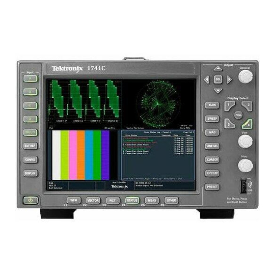
Procedure column in the table refers you to a procedure in this manual that explains how to use the element. A reference of None means that the element is an indicator only or has no associated procedure. Figure 1: 1741C front panel 1741C Analog Dual-Standard Waveform Monitor User Manual... -
Page 38: Table 5: Front Panel Controls
Parameter (See page 37.) Vertical and Horizontal Knobs Use to position waveforms when displayed in tiles or full screen. Power standby button Press to put instrument in standby mode. Other button LTC display mode. 1741C Analog Dual-Standard Waveform Monitor User Manual... -
Page 39: Rear-Panel Connectors
Systems with both current-carrying conductors live with respect to ground (such as phase-to-phase in multiphase systems) are not recommended as power sources. NOTE. Only the line conductor is fused for over-current protection. The fuse is internal. 1741C Analog Dual-Standard Waveform Monitor User Manual... - Page 40 Table 6 shows the display output. The display resolution is 1024 x 768. The output is compatible with standard analog PC monitors, either CRT or LCD-based. Pin Assignment The EXT DISPLAY connector is a 15-pin D-type connector with socket contacts. 1741C Analog Dual-Standard Waveform Monitor User Manual...
-
Page 41: Table 6: Ext Display Connector Pin Assignments
Table 7: Pix Mon connector pin assignments Pin name Red Video Green Video Blue Video Not connected Ground Red Ground Green Ground Blue Ground Not Connected Not Connected Not Connected Not Connected Horizontal Sync Vertical Sync Not Connected 1741C Analog Dual-Standard Waveform Monitor User Manual... -
Page 42: Table 8: Remote Connector Pin Assignments
Closure and Pin Out Table 9: Pin assignments Pins Function GND (Out) LTC IN + LTC IN – GND (Out) GND Closure Out Preset A1 (In) Preset A2 (In) Preset A3 (In) Preset A4 (In) 1741C Analog Dual-Standard Waveform Monitor User Manual... -
Page 43: Instrument Display
Note that the button you select lights and that a light-blue outline surrounds the tile. Both the lighted button and the light-blue outline indicate the active, selected tile. Tile 3 is shown selected here. 1741C Analog Dual-Standard Waveform Monitor User Manual... - Page 44 4. To select another tile, push its button. The tile you select will replace the previously selected tile, displaying full screen. 5. Push the FULL button again to toggle to the four-tile display. 1741C Analog Dual-Standard Waveform Monitor User Manual...
-
Page 45: Figure 3: Status Bar In Single Input Mode
Current Input Text indicating the selected input. Possible inputs are: Cmpst A, Cmpst B, Cmpst C and Cmpst D. Also indicates if the current input is not in Auto mode and is unlocked. 1741C Analog Dual-Standard Waveform Monitor User Manual... -
Page 46: Selecting A Display
VECTOR - Vector display of the video signal STATUS - extensive displays MEAS - a Tektronix proprietary display that simplifies timing correction. OTHER - display for checking the LTC amplitude and noise, and for verifying that LTC is locked to the video... -
Page 47: Setting Measurement Parameters
3. When the menu opens, make your selections as described in the steps that follow. a. Use the right and left keys to traverse between menu panels. The instrument surrounds the panel selected with a blue border. 1741C Analog Dual-Standard Waveform Monitor User Manual... -
Page 48: Selecting Signal Inputs
1. Connect analog composite signals to the A, B, C, or D composite inputs at the rear panel. 2. Terminate each loop through input properly at the rear panel for any inputs that are not routed to another device. 1741C Analog Dual-Standard Waveform Monitor User Manual... -
Page 49: Using Multi Mode
If any input is disabled, the associated letter is replaced with a ’-’. For example, if input B is disabled, the input line will read “MULTI: A-CD”. The Alarm feature is disabled in MULTI mode. 1741C Analog Dual-Standard Waveform Monitor User Manual... -
Page 50: Setting Gain Sweep And Magnification
2. Press and hold the GAIN button. 3. If you enable VAR Gain, set the gain that you want using the GENERAL knob. 4. If you select Gain Settings, you can choose x2, x5, or x10 gain. 1741C Analog Dual-Standard Waveform Monitor User Manual... -
Page 51: Using Presets
3. Press the PRESET button. 4. Press and hold the lighted button of the measurement you want to save until the Preset # saved message appears on the screen. The setup will be stored for later recall. 1741C Analog Dual-Standard Waveform Monitor User Manual... -
Page 52: Measuring Waveforms With Cursors
To quickly center the active cursor on screen, press and hold the SEL button. 5. Repeat steps 3 and 4 to adjust the other cursor. 6. Read the cursor measurement in the Cursors readout. 1741C Analog Dual-Standard Waveform Monitor User Manual... - Page 53 You can display independent cursors in all four tiles at the same time. Cursors track the live trace, so they may not be correctly registered on a frozen trace. 1741C Analog Dual-Standard Waveform Monitor User Manual...
-
Page 54: Capturing The Display
NOTE. The display mode setting is specific to the selected tile, and each tile can be set independently. Halting the Display Update Push the FREEZE button. For most displays, this will stop updates. 1741C Analog Dual-Standard Waveform Monitor User Manual... -
Page 55: Setting Line Select Mode
F4 (field 4), or All. 4. The line and field information will appear at the bottom of the display screen. 5. Turn the GENERAL knob to select the line you want to view. 1741C Analog Dual-Standard Waveform Monitor User Manual... -
Page 56: Configuring Your Instrument
The Configuration menu is displayed on the top or bottom half of the screen opposite the active tile. 2. Use the left/right arrow keys to move the selection among panels. The selected, active pane has a blue outline. 1741C Analog Dual-Standard Waveform Monitor User Manual... -
Page 57: Connecting Directly To A Pc
2. Set up the monitor as though you are going to connect to a network. Choose Manual IP mode and set the IP address manually. Be sure to set an address that is compatible with the setting of your PC. 1741C Analog Dual-Standard Waveform Monitor User Manual... - Page 58 Operating Basics 1741C Analog Dual-Standard Waveform Monitor User Manual...
-
Page 59: Tutorial: Timing A Studio
12. Press the MAG button to increase the timing resolution. 13. Press the FREEZE button to save the waveform as a baseline. 14. Apply an input that needs to match the timing of the first input. 1741C Analog Dual-Standard Waveform Monitor User Manual... - Page 60 field rate displays without Mag active to show the location of significantly mistimed signals. Using the Timing-Display The Tektronix Timing Display provides a quick, easy way to measure the timing of an input relative to the external reference: Method The rectangular display automatically scales to match the input signal. For composite inputs, the display represents one color frame.
- Page 61 Saved Offset. In this mode, you can save the timing from a master signal relative to the reference as the zero point offset. Then route other inputs and measure relative to this saved offset. To time the inputs to a router: 1741C Analog Dual-Standard Waveform Monitor User Manual...
- Page 62 In the Relative to: Saved Offset mode, it has no effect. This timing relationship between input and reference is also compatible with the waveform mode. If you have zero timing on the Timing display 1741C Analog Dual-Standard Waveform Monitor User Manual...
- Page 63 Because the timing display chooses the smallest of the possible timing offsets, if a large timing difference exists between two inputs, they may not be matched. 1741C Analog Dual-Standard Waveform Monitor User Manual...
- Page 64 Operating Basics 1741C Analog Dual-Standard Waveform Monitor User Manual...
-
Page 65: Reference
Safe Area Graticules, accessed in the Picture menu. 5. If you want, to set the Height, Width, and Offsets of the title and action areas for Custom Safe Graticules 1 and 2, first select the title or action to change. 1741C Analog Dual-Standard Waveform Monitor User Manual... - Page 66 Graticules Configuration menu. (See the procedure Configuring Safe Area Graticules, step 5.) 5. Repeat step 4 for each Safe Area selection. 6. Press the PICT button again to dismiss the pop-up menu. 1741C Analog Dual-Standard Waveform Monitor User Manual...
- Page 67 Safe Area Graticules can globally be configured to comply to accepted standards in the Configuration menu. Custom selections for vertical and horizontal size and offset of the Safe Areas can be set in the Configuration menu. 1741C Analog Dual-Standard Waveform Monitor User Manual...
- Page 68 Reference 1741C Analog Dual-Standard Waveform Monitor User Manual...
-
Page 69: Appendix A: Alarms
Timecode Ltc Missing Indicates that a break or discontinuity in the LTC has occurred Timecode Ltc Invalid Indicates that the LTC was lost for one frame but has reappeared 1741C Analog Dual-Standard Waveform Monitor User Manual... -
Page 70: Configuring Alarms
Use the following procedure to set the alarm responses globally (using the arrow keys and SEL button to make selections): Globally 1. Press the CONFIG button to display the Configuration menu. 2. Select Alarms. 3. Navigate to Set all Alarms to this Mask. 1741C Analog Dual-Standard Waveform Monitor User Manual... - Page 71 You can monitor alarm status. (See page 52, Monitoring Alarms.) Enabling Alarms The channels for which you enable alarms trigger your previously defined alarm responses (use the arrow keys and SEL button to make selections): 1741C Analog Dual-Standard Waveform Monitor User Manual...
-
Page 72: Monitoring Alarms
OK (green) Alarm is enabled for reporting and has not detected errors for at least 5 seconds. Error (yellow) Alarm condition cleared for less than 5 seconds. Error (red) Alarm triggered now. 1741C Analog Dual-Standard Waveform Monitor User Manual... -
Page 73: Appendix B: Upgrading Instrument Software
Download the latest version of the instrument software to a USB memory device by performing the following procedure: 1. Using an Ethernet connection on a PC, navigate to the Tektronix Web site at http://www.tek.com/products/video_test. 2. Click on the Download Software link, and then select the Video/Audio Signal Monitors link. - Page 74 1. Insert a USB memory device into the USB drive of the instrument. 2. Press CONFIG > Utilities > System Upgrade > Upgrade Options > USB Upgrade and then press the SEL button. 1741C Analog Dual-Standard Waveform Monitor User Manual...
-
Page 75: Network Upgrade
Download the latest version of the instrument software to a PC by performing the following procedure: 1. Using an Ethernet connection, navigate to the Tektronix Web site at http://www.tek.com/products/video_test. 2. Click on the Download Software link, and then select the Video/Audio Signal Monitors link. - Page 76 5. Press CONFIG > Utilities > System Upgrade > Upgrade Options > Network Upgrade and then press the SEL button. 6. On the PC, double-click the transfer.exe file to launch the transfer program. This displays the following window. 1741C Analog Dual-Standard Waveform Monitor User Manual...
-
Page 77: Upgrading Multiple Instruments With A Pc
< HOSTS.TXT NOTE. You can also place the instrument into the upgrade mode by pressing and holding the CURSOR button during power up until the button light goes out. 1741C Analog Dual-Standard Waveform Monitor User Manual... -
Page 78: Verifying The Upgrade
To verify the functional performance of your instrument, perform the Incoming Inspection procedures. NOTE. See the Readme.txt file that is included with the software-upgrade package to determine whether all of the current Configuration menu and instrument-mode settings were preserved through upgrading. 1741C Analog Dual-Standard Waveform Monitor User Manual... - Page 79 100 IRE. Composite Video A single video signal containing all of the necessary information to reproduce a color picture. Defaults A set of behaviors specified on every system. You can later change these specifications. 1741C Analog Dual-Standard Waveform Monitor User Manual...
- Page 80 Acronym for Phase Alternate Line. One of the television systems used in Europe and many other parts of the world. The phase of one of the color difference signals alternates from line to line to help cancel out phase errors. 1741C Analog Dual-Standard Waveform Monitor User Manual...
- Page 81 Synchronizing information appears between fields and tells the picture monitor to go back to the top of the screen to begin another vertical scan. Abbreviation for luminance. 1741C Analog Dual-Standard Waveform Monitor User Manual...
- Page 82 Glossary 1741C Analog Dual-Standard Waveform Monitor User Manual...
- Page 83 Pix, 21 Information levels of, 17 Power, 19 where to find more, xiii scope of, 17 Remote, 22 Inputs Frozen Only Video input, 20 How to select, 28 Freeze pop-up menu, 34 XGA, 20 1741C Analog Dual-Standard Waveform Monitor User Manual...
- Page 84 2, 3 Operating Considerations, 3 Signal connection Operation Line-termination Basic, 17 requirements, 5 control levels (types), 17 Software Upgrade, 53 phase style, 47 Status XGA Output connector, 20 determining, 25 PC System Requirements, 53 1741C Analog Dual-Standard Waveform Monitor User Manual...
Need help?
Do you have a question about the 1741C and is the answer not in the manual?
Questions and answers